2008 INFINITI FX35 installation
[x] Cancel search: installationPage 3000 of 3924
DOOR MIRRORGW-87
< SERVICE INFORMATION >
C
DE
F
G H
J
K L
M A
B
GW
N
O P
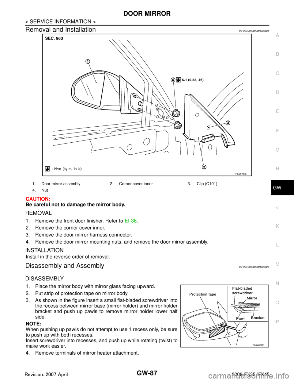
Removal and InstallationINFOID:0000000001328024
CAUTION:
Be careful not to damage the mirror body.
REMOVAL
1. Remove the front door finisher. Refer to EI-36.
2. Remove the corner cover inner.
3. Remove the door mirror harness connector.
4. Remove the door mirror mounting nuts, and remove the door mirror assembly.
INSTALLATION
Install in the reverse order of removal.
Disassembly and AssemblyINFOID:0000000001328025
DISASSEMBLY
1. Place the mirror body with mirror glass facing upward.
2. Put strip of protection tape on mirror body.
3. As shown in the figure insert a small flat-bladed screwdriver into the recess between mirror base (mirror holder) and mirror holder
bracket and push up pawls to remove mirror holder lower half
side.
NOTE:
When pushing up pawls do not attempt to use 1 recess only, be sure
to push up with both recesses.
Insert screwdriver into recesses, and push up while rotating (twist) to
make work easier.
4. Remove terminals of mirror heater attachment.
PIIA4738E
1. Door mirror assembly 2. Corn er cover inner 3. Clip (C101)
4. Nut
PIIA4002E
3AA93ABC3ACD3AC03ACA3AC03AC63AC53A913A773A893A873A873A8E3A773A983AC73AC93AC03AC3
3A893A873A873A8F3A773A9D3AAF3A8A3A8C3A863A9D3AAF3A8B3A8C
Page 3001 of 3924
GW-88
< SERVICE INFORMATION >
DOOR MIRROR
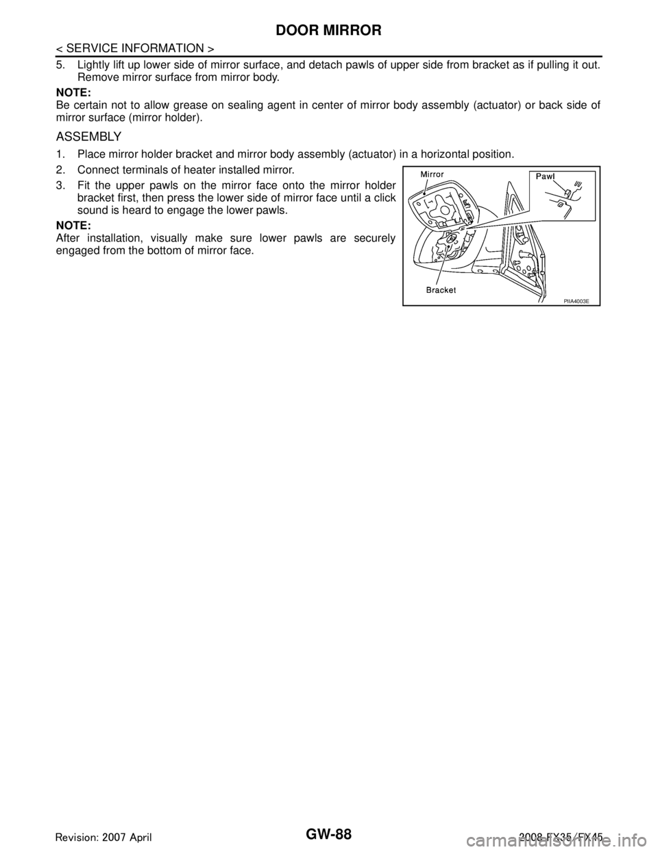
5. Lightly lift up lower side of mirror surface, and detach pawls of upper side from bracket as if pulling it out.
Remove mirror surface from mirror body.
NOTE:
Be certain not to allow grease on sealing agent in cent er of mirror body assembly (actuator) or back side of
mirror surface (mirror holder).
ASSEMBLY
1. Place mirror holder bracket and mirror body assembly (actuator) in a horizontal position.
2. Connect terminals of heater installed mirror.
3. Fit the upper pawls on the mirror face onto the mirror holder bracket first, then press the lower side of mirror face until a click
sound is heard to engage the lower pawls.
NOTE:
After installation, visually make sure lower pawls are securely
engaged from the bottom of mirror face.
PIIA4003E
3AA93ABC3ACD3AC03ACA3AC03AC63AC53A913A773A893A873A873A8E3A773A983AC73AC93AC03AC3
3A893A873A873A8F3A773A9D3AAF3A8A3A8C3A863A9D3AAF3A8B3A8C
Page 3002 of 3924
IP-1
BODY
C
DE
F
G H
J
K L
M
SECTION IP
A
B
IP
N
O P
CONTENTS
INSTRUMENT PANEL
SERVICE INFORMATION .. ..........................2
PRECAUTIONS .............................................. .....2
Precaution for Supplemental Restraint System
(SRS) "AIR BAG" and "SEAT BELT PRE-TEN-
SIONER" ............................................................. ......
2
Precaution .................................................................2
PREPARATION ...................................................3
Special Service Tool ........................................... ......3
Commercial Service Tool ..........................................3
SQUEAK AND RATTLE TROUBLE DIAG-
NOSES ...............................................................
4
Work Flow ............................................................ .....4
Generic Squeak and Rattle Troubleshooting ............6
Diagnostic Worksheet ...............................................8
INSTRUMENT PANEL ASSEMBLY .................10
Component Parts Location ......................................10
Removal and Installation .........................................11
Disassembly and Assembly .....................................16
3AA93ABC3ACD3AC03ACA3AC03AC63AC53A913A773A893A873A873A8E3A773A983AC73AC93AC03AC3
3A893A873A873A8F3A773A9D3AAF3A8A3A8C3A863A9D3AAF3A8B3A8C
Page 3003 of 3924
IP-2
< SERVICE INFORMATION >
PRECAUTIONS
SERVICE INFORMATION
PRECAUTIONS
Precaution for Supplemental Restraint System (SRS) "AIR BAG" and "SEAT BELT
PRE-TENSIONER"
INFOID:0000000001612902
The Supplemental Restraint System such as “A IR BAG” and “SEAT BELT PRE-TENSIONER”, used along
with a front seat belt, helps to reduce the risk or severi ty of injury to the driver and front passenger for certain
types of collision. This system includes seat belt switch inputs and dual stage front air bag modules. The SRS
system uses the seat belt switches to determine the front air bag deployment, and may only deploy one front
air bag, depending on the severity of a collision and w hether the front occupants are belted or unbelted.
Information necessary to service the system safely is included in the “SUPPLEMENTAL RESTRAINT SYS-
TEM” and “SEAT BELTS” of this Service Manual.
WARNING:
• To avoid rendering the SRS inopera tive, which could increase the risk of personal injury or death in
the event of a collision which would result in air bag inflation, all maintenance must be performed by
an authorized NISS AN/INFINITI dealer.
Improper maintenance, including in correct removal and installation of the SRS, can lead to personal
injury caused by unintent ional activation of the system. For re moval of Spiral Cable and Air Bag
Module, see the “SUPPLEMEN TAL RESTRAINT SYSTEM”.
Do not use electrical test equipmen t on any circuit related to the SRS unless instructed to in this
Service Manual. SRS wiring harnesses can be identi fied by yellow and/or orange harnesses or har-
ness connectors.
PrecautionINFOID:0000000001328081
Disconnect both battery cables in advance.
Disconnect air bag system line in advance.
Never tamper with or force air bag lid open, as this may adversely affect air bag performance.
Be careful not to scratch pad and other parts.
When removing or disassembling any part, be careful not to damage or deform it. Protect parts, which may get in the way with cloth.
When removing parts with a screwdriver or other tool, protect parts by wrapping them with vinyl or tape.
Keep removed parts protected with cloth.
If a clip is deformed or damaged, replace it.
If an unreusable part is removed, replace it with a new one.
Tighten bolts and nuts firmly to the specified torque.
After re-assembly has been completed, make sure each part functions correctly.
Remove stains in the following way.
Water-soluble stains:
Dip a soft cloth in warm water, and then squeeze it tightly. After wiping the stain, wipe with a soft dry cloth.
Oil stain:
Dissolve a synthetic detergent in warm water (density of 2 to 3% or less), dip the cloth, then clean off the stain
with the cloth. Next, dip the cloth in fresh water and squeeze it tightly. Then clean off the detergent completely.
Then wipe the area with a soft dry cloth.
Do not use any organic solvent, such as thinner or benzine.
3AA93ABC3ACD3AC03ACA3AC03AC63AC53A913A773A893A873A873A8E3A773A983AC73AC93AC03AC3
3A893A873A873A8F3A773A9D3AAF3A8A3A8C3A863A9D3AAF3A8B3A8C
Page 3007 of 3924
IP-6
< SERVICE INFORMATION >
SQUEAK AND RATTLE TROUBLE DIAGNOSES
Insulates where slight movement is present. Ideal for instrument panel applications.
SILICONE GREASE
Used in of UHMW tape that will be visible or not fit.
Note: Will only last a few months.
SILICONE SPRAY
Use when grease cannot be applied.
DUCT TAPE
Use to eliminate movement.
CONFIRM THE REPAIR
Confirm that the cause of a noise is repaired by test driving the vehicle. Operate the vehicle under the same
conditions as when the noise originally occurred. Refer to the notes on the Diagnostic Worksheet.
Generic Squeak and Rattle TroubleshootingINFOID:0000000001328085
Refer to Table of Contents for specific component removal and installation information.
INSTRUMENT PANEL
Most incidents are caused by contact and movement between:
1. The cluster lid A and instrument panel
2. Acrylic lens and combination meter housing
3. Instrument panel to front pillar garnish
4. Instrument panel to windshield
5. Instrument panel mounting pins
6. Wiring harnesses behind the combination meter
7. A/C defroster duct and duct joint
These incidents can usually be located by tapping or moving the components to duplicate the noise or by
pressing on the components while driving to stop the noi se. Most of these incidents can be repaired by apply-
ing felt cloth tape or silicon spray (in hard to reach areas). Urethane pads can be used to insulate wiring har-
ness.
CAUTION:
Do not use silicone spray to isolate a squeak or ra ttle. If you saturate the area with silicone, you will
not be able to recheck the repair.
CENTER CONSOLE
Components to pay attention to include:
1. Shifter assembly cover to finisher
2. A/C control unit and cluster lid C
3. Wiring harnesses behind audio and A/C control unit
The instrument panel repair and isolation pr ocedures also apply to the center console.
DOORS
Pay attention to the:
1. Finisher and inner panel making a slapping noise
2. Inside handle escutcheon to door finisher
3. Wiring harnesses tapping
4. Door striker out of alignment causing a popping noise on starts and stops
Tapping or moving the components or pressing on them wh ile driving to duplicate the conditions can isolate
many of these incidents. You can usually insulate the areas with felt cloth tape or insulator foam blocks from
the NISSAN Squeak and Rattle Kit (J43980) to repair the noise.
TRUNK
Trunk noises are often caused by a loose jack or loose items put into the trunk by the owner.
In addition look for:
1. Trunk lid dumpers out of adjustment
2. Trunk lid striker out of adjustment
3. The trunk lid torsion bars knocking together
4. A loose license plate or bracket
3AA93ABC3ACD3AC03ACA3AC03AC63AC53A913A773A893A873A873A8E3A773A983AC73AC93AC03AC3
3A893A873A873A8F3A773A9D3AAF3A8A3A8C3A863A9D3AAF3A8B3A8C
Page 3012 of 3924
INSTRUMENT PANEL ASSEMBLYIP-11
< SERVICE INFORMATION >
C
DE
F
G H
J
K L
M A
B
IP
N
O P
Removal and InstallationINFOID:0000000001328088
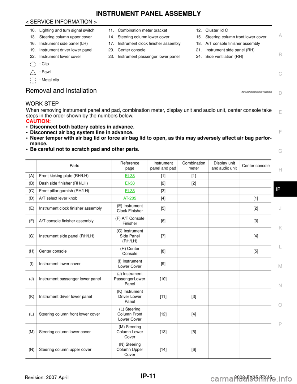
WORK STEP
When removing instrument panel and pad, combination me ter, display unit and audio unit, center console take
steps in the order shown by the numbers below.
CAUTION:
Disconnect both battery cables in advance.
Disconnect air bag system line in advance.
Never temper with air bag lid or force air bag lid to open, as this may adversely affect air bag perfor-
mance.
Be careful not to scratch pad and other parts.
10. Lighting and turn signal switch 11. Combination meter bracket 12. Cluster lid C
13. Steering column upper cover 14. Steering column lower cover 15. Steering column front lower cover
16. Instrument side panel (LH) 17. Instrument clock finisher assembly 18. A/T console finisher assembly
19. Instrument driver lower panel 20. Center console 21. Instrument side panel (RH)
22. Instrument lower cover 23. Instrument passenger lower panel 24. Side ventilation (RH)
: Clip
: Pawl
: Metal clip
Parts Reference
page Instrument
panel and pad Combination
meter Display unit
and audio unit Center console
(A) Front kicking plate (RH/LH) EI-38
[1] [1]
(B) Dash side finisher (RH/LH) EI-38
[2] [2]
(C) Front pillar garnish (RH/LH) EI-38
[3]
(D) A/T select lever knob AT- 2 0 5
[4] [1]
(E) Instrument clock finisher assembly (E) Instrument
Clock Finisher [5] [2]
(F) A/T console finisher assembly (F) A/T Console
Finisher [6] [3]
(G) Instrument side panel (RH/LH) (G) Instrument
Side Panel (RH/LH) [7] [4]
(H) Center console (H) Center
Console [8] [5]
(I) Instrument lower cover (I) Instrument
Lower Cover [9]
(J) Instrument passenger lower panel (J) Instrument
Passenger Lower
Panel [10]
(K) Instrument driver lower panel (K) Instrument
Driver Lower Panel [11] [3]
(L) Steering column front lower cover (L) Steering
Column Front Lower Cover [12] [4]
(M) Steering column lower cover (M) Steering
Column Lower
Cover [13] [5]
(N) Steering column upper cover (N) Steering
Column Upper Cover [14] [6]
3AA93ABC3ACD3AC03ACA3AC03AC63AC53A913A773A893A873A873A8E3A773A983AC73AC93AC03AC3
3A893A873A873A8F3A773A9D3AAF3A8A3A8C3A863A9D3AAF3A8B3A8C
Page 3013 of 3924
![INFINITI FX35 2008 Service Manual
IP-12
< SERVICE INFORMATION >
INSTRUMENT PANEL ASSEMBLY
[]: Number indicates step in removal procedures.
REMOVAL
(A) Front Kicking Plate (RH/LH)
Remove front kicking plate (RH/LH). Refer to EI-38.
(B INFINITI FX35 2008 Service Manual
IP-12
< SERVICE INFORMATION >
INSTRUMENT PANEL ASSEMBLY
[]: Number indicates step in removal procedures.
REMOVAL
(A) Front Kicking Plate (RH/LH)
Remove front kicking plate (RH/LH). Refer to EI-38.
(B](/manual-img/42/57017/w960_57017-3012.png)
IP-12
< SERVICE INFORMATION >
INSTRUMENT PANEL ASSEMBLY
[]: Number indicates step in removal procedures.
REMOVAL
(A) Front Kicking Plate (RH/LH)
Remove front kicking plate (RH/LH). Refer to EI-38.
(B) Dash Side Finisher (RH/LH)
1. Remove plastics nut.
2. Remove dash side finisher (RH/LH). Refer to EI-38
.
(C) Front Pillar Garnish (RH/LH)
Pull to inside of vehicle, disengage metal clips and remove front pillar garnish. Refer to EI-38.
(D) A/T Select Lever Knob
1. Pull down knob cover.
2. Remove lock-pin of select lever knob.
3. Lift up select lever knob and remove select lever knob.
Refer to AT-205, "
Control Device Removal and Installation".
(E) Instrument Clock Finisher
1. Remove screw and then pull back to your side of instrument
clock finisher.
2. Disconnect clips and harness connector, and remove instrument clock finisher.
(F) A/T Console Finisher
(O) Wiper and washer switch (O) Wiper and
Washer Switch [15] [7]
(P) Lighting and turn signal switch (P) Lighting and
Turn Signal Switch [16] [8]
(Q) Steering lock escutcheon (Q) Steering Lock
Escutcheon [17] [9]
(R) Combination meter assembly (R) Combination
Meter Assembly [18] [10]
(S) Cluster lid C (S) Cluster Lid C [19] [1] (T) Display unit and audio unit (T) Display Unit
and Audio Unit [20] [2]
(U) Front defroster grille (RH/LH) (U) Front
Defroster Grille (RH/LH) [21]
(V) Combination meter bracket (V) Combination
Meter Bracket [22]
(W) Side ventilation (RH/LH) (W) Side
Ventilation (RH/LH) [23]
(X) Instrument panel and pad (X) Instrument
Panel and Pad [24]
Parts
Reference
page Instrument
panel and pad Combination
meter Display unit
and audio unit Center console
: Clip
: Pawl
PIIB8535E
3AA93ABC3ACD3AC03ACA3AC03AC63AC53A913A773A893A873A873A8E3A773A983AC73AC93AC03AC3
3A893A873A873A8F3A773A9D3AAF3A8A3A8C3A863A9D3AAF3A8B3A8C
Page 3015 of 3924
IP-14
< SERVICE INFORMATION >
INSTRUMENT PANEL ASSEMBLY
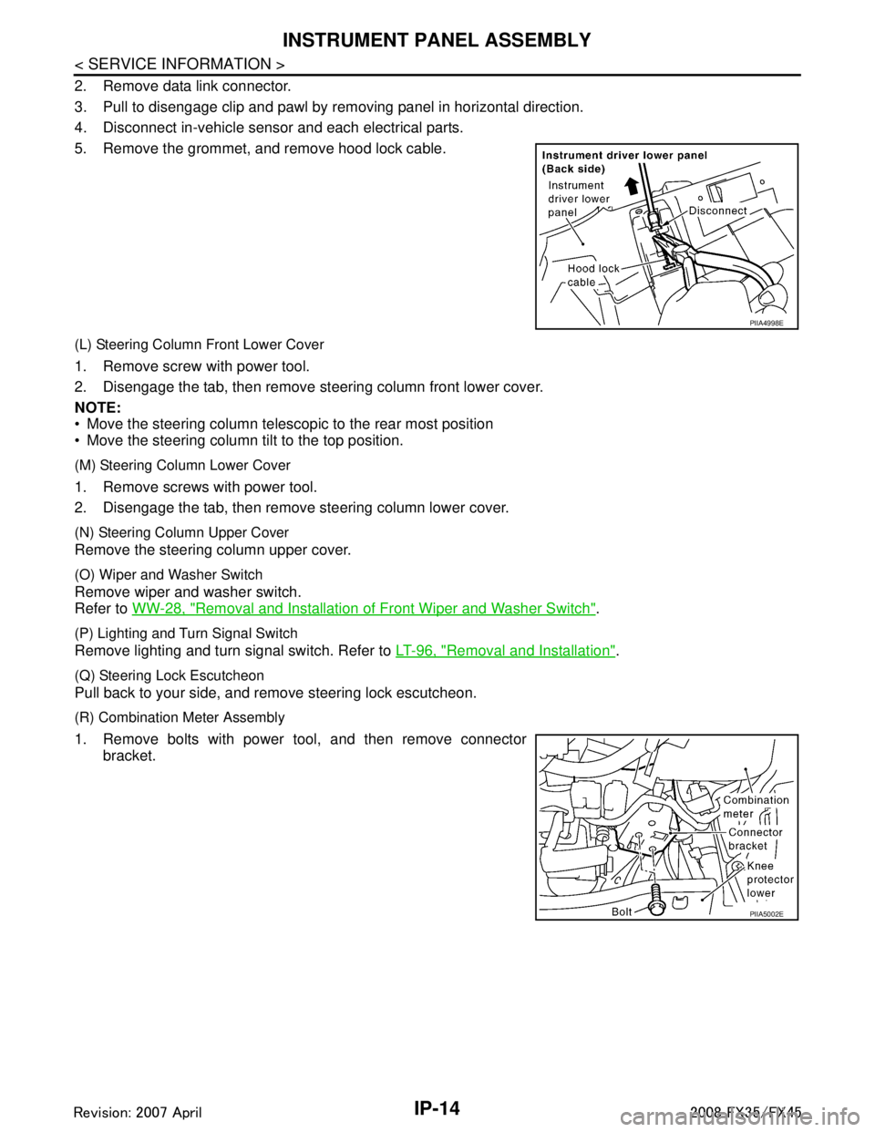
2. Remove data link connector.
3. Pull to disengage clip and pawl by removing panel in horizontal direction.
4. Disconnect in-vehicle sensor and each electrical parts.
5. Remove the grommet, and remove hood lock cable.
(L) Steering Column Front Lower Cover
1. Remove screw with power tool.
2. Disengage the tab, then remove steering column front lower cover.
NOTE:
Move the steering column telescopic to the rear most position
Move the steering column tilt to the top position.
(M) Steering Column Lower Cover
1. Remove screws with power tool.
2. Disengage the tab, then remove steering column lower cover.
(N) Steering Column Upper Cover
Remove the steering column upper cover.
(O) Wiper and Washer Switch
Remove wiper and washer switch.
Refer to WW-28, "
Removal and Installation of Front Wiper and Washer Switch".
(P) Lighting and Turn Signal Switch
Remove lighting and turn signal switch. Refer to LT-96, "Removal and Installation".
(Q) Steering Lock Escutcheon
Pull back to your side, and remove steering lock escutcheon.
(R) Combination Meter Assembly
1. Remove bolts with power tool, and then remove connector
bracket.
PIIA4998E
PIIA5002E
3AA93ABC3ACD3AC03ACA3AC03AC63AC53A913A773A893A873A873A8E3A773A983AC73AC93AC03AC3
3A893A873A873A8F3A773A9D3AAF3A8A3A8C3A863A9D3AAF3A8B3A8C