2008 INFINITI FX35 installation
[x] Cancel search: installationPage 3100 of 3924
![INFINITI FX35 2008 Service Manual
LAN-80
< SERVICE INFORMATION >[CAN]
TROUBLE DIAGNOSIS
2.CHECK HARNESS FOR OPEN CIRCUIT
1. Disconnect the connector of driver seat control unit.
2. Check the resistance between the driver seat contro INFINITI FX35 2008 Service Manual
LAN-80
< SERVICE INFORMATION >[CAN]
TROUBLE DIAGNOSIS
2.CHECK HARNESS FOR OPEN CIRCUIT
1. Disconnect the connector of driver seat control unit.
2. Check the resistance between the driver seat contro](/manual-img/42/57017/w960_57017-3099.png)
LAN-80
< SERVICE INFORMATION >[CAN]
TROUBLE DIAGNOSIS
2.CHECK HARNESS FOR OPEN CIRCUIT
1. Disconnect the connector of driver seat control unit.
2. Check the resistance between the driver seat control unit harness connector terminals.
OK or NG
OK >> GO TO 3.
NG >> Repair the driver seat control unit branch line.
3.CHECK POWER SUPPLY AND GROUND CIRCUIT
Check the power supply and the ground circuit of the driver seat control unit. Refer to SE-18, "
Schematic".
OK or NG
OK >> Present error: Replace the driver seat control unit. Refer to SE-16, "Component Parts and Har-
ness Connector Location".
Past error: Error was detected in t he driver seat control unit branch line.
NG >> Repair the power supply and the ground circuit.
IPDM E/R Branch Line CircuitINFOID:0000000001328668
INSPECTION PROCEDURE
1.CHECK CONNECTOR
1. Turn the ignition switch OFF.
2. Disconnect the battery cable from the negative terminal.
3. Check the following terminals and connectors fo r damage, bend and loose connection (unit side and con-
nector side).
- IPDM E/R
- Harness connector E205
- Harness connector B5
OK or NG
OK >> GO TO 2.
NG >> Repair the terminal and connector.
2.CHECK HARNESS FOR OPEN CIRCUIT
1. Disconnect the connector of IPDM E/R.
2. Check the resistance between the IPDM E/R harness connector terminals.
OK or NG
OK >> GO TO 3.
NG >> Repair the IPDM E/R branch line.
3.CHECK POWER SUPPLY AND GROUND CIRCUIT
Check the power supply and the ground circuit of the IPDM E/R. Refer to PG-23, "
IPDM E/R Power/Ground
Circuit Inspection".
OK or NG
OK >> Present error: Replace the IPDM E/R. Refer to PG-24, "Removal and Installation of IPDM E/R".
Past error: Error was detected in the IPDM E/R branch line.
NG >> Repair the power supply and the ground circuit.
Driver seat control unit harness connector Resistance (Ω)
Connector No. Terminal No.
B152 14 15 Approx. 54 – 66
IPDM E/R harness connector Resistance (Ω)
Connector No. Terminal No.
E9 48 49 Approx. 108 – 132
3AA93ABC3ACD3AC03ACA3AC03AC63AC53A913A773A893A873A873A8E3A773A983AC73AC93AC03AC3
3A893A873A873A8F3A773A9D3AAF3A8A3A8C3A863A9D3AAF3A8B3A8C
Page 3103 of 3924
LT-1
ELECTRICAL
C
DE
F
G H
I
J
L
M
SECTION LT
A
B
LT
N
O P
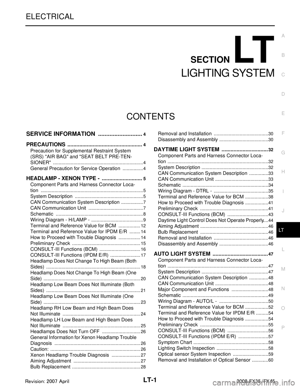
CONTENTS
LIGHTING SYSTEM
SERVICE INFORMATION .. ..........................4
PRECAUTIONS .............................................. .....4
Precaution for Supplemental Restraint System
(SRS) "AIR BAG" and "SEAT BELT PRE-TEN-
SIONER" ............................................................. ......
4
General Precaution for Service Operation ................4
HEADLAMP - XENON TYPE - ............................5
Component Parts and Harness Connector Loca-
tion ...................................................................... ......
5
System Description ...................................................5
CAN Communication System Description .................7
CAN Communication Unit .........................................7
Schematic .................................................................8
Wiring Diagram - H/LAMP - .......................................9
Terminal and Reference Value for BCM .................12
Terminal and Reference Value for IPDM E/R .........14
How to Proceed with Trouble Diagnosis .................14
Preliminary Check ...................................................15
CONSULT-III Functions (BCM) ...............................16
CONSULT-III Functions (IPDM E/R) .......................17
Headlamp Does Not Change To High Beam (Both
Sides) ......................................................................
18
Headlamp Does Not Change To High Beam (One
Side) ........................................................................
20
Headlamp Low Beam Does Not Illuminate (Both
Sides) .................................................................. ....
21
Headlamp Low Beam Does Not Illuminate (One
Side) .................................................................... ....
23
Headlamp RH Low Beam and High Beam Does
Not Illuminate ..........................................................
24
Headlamp LH Low Beam and High Beam Does
Not Illuminate ..........................................................
25
Headlamps Does Not Turn OFF .............................26
General Information for Xenon Headlamp Trouble
Diagnosis ................................................................
26
Caution: ...................................................................26
Xenon Headlamp Trouble Diagnosis ......................27
Aiming Adjustment ..................................................27
Bulb Replacement ...................................................28
Removal and Installation ..................................... ....30
Disassembly and Assembly .....................................30
DAYTIME LIGHT SYSTEM ...............................32
Component Parts and Harness Connector Loca-
tion ....................................................................... ....
32
System Description ..................................................32
CAN Communication System Description ...............33
CAN Communication Unit ........................................33
Schematic ................................................................34
Wiring Diagram - DTRL - .........................................35
Terminal and Reference Value for BCM ..................38
How to Proceed with Trouble Diagnosis ..................41
Preliminary Check ...................................................41
CONSULT-III Functions (BCM) ...............................43
Daytime Light Control Does Not Operate Properly ....44
Aiming Adjustment ...................................................46
Bulb Replacement ...................................................46
Removal and Installation .........................................46
Disassembly and Assembly .....................................46
AUTO LIGHT SYSTEM .....................................47
Component Parts and Harness Connector Loca-
tion ...........................................................................
47
System Description ..................................................47
CAN Communication System Description ...............48
CAN Communication Unit ........................................48
Major Component and Functions ............................48
Schematic ................................................................49
Wiring Diagram - AUTO/L - .....................................50
Terminal and Reference Value for BCM ..................52
Terminal and Reference Value for IPDM E/R ..........54
How to Proceed with Trouble Diagnosis ..................54
Preliminary Check ...................................................55
CONSULT-III Functions (BCM) ...............................56
CONSULT-III Functions (IPDM E/R) .......................57
Symptom Chart ........................................................58
Lighting Switch Inspection .......................................58
Optical sensor System Inspection ...........................59
Removal and Installation of Optical Sensor .............60
3AA93ABC3ACD3AC03ACA3AC03AC63AC53A913A773A893A873A873A8E3A773A983AC73AC93AC03AC3
3A893A873A873A8F3A773A9D3AAF3A8A3A8C3A863A9D3AAF3A8B3A8C
Page 3104 of 3924

LT-2
HEADLAMP AIMING CONTROL ......................61
Schematic ............................................................ ...61
Wiring Diagram - H/AIM - .......................................62
Removal and Installation ........................................64
Switch Circuit Inspection ........................................65
FRONT FOG LAMP ...........................................66
Component Parts and Harness Connector Loca-
tion ....................................................................... ...
66
System Description .................................................66
CAN Communication System Description ..............67
CAN Communication Unit .......................................67
Wiring Diagram - F/FOG - ......................................68
Terminal and Reference Value for BCM .................69
Terminal and Reference Value for IPDM E/R .........70
How to Proceed with Trouble Diagnosis .................71
Preliminary Check ..................................................71
CONSULT-III Functions (BCM) ..............................72
CONSULT-III Functions (IPDM E/R) ......................72
Front Fog Lamps Do Not Illuminate (Both Sides) ...72
Front Fog Lamp Does Not Illuminate (One Side) ...74
Aiming Adjustment ..................................................75
Bulb Replacement ..................................................76
Removal and Installation ........................................76
TURN SIGNAL AND HAZARD WARNING
LAMPS ...............................................................
78
Component Parts and Harness Connector Loca-
tion ....................................................................... ...
78
System Description .................................................78
CAN Communication System Description ..............80
CAN Communication Unit .......................................80
Schematic ...............................................................81
Wiring Diagram - TURN - ........................................82
Terminal and Reference Value for BCM .................84
Terminal and Reference Value for Rear Combina-
tion Lamp Control Unit ............................................
86
How to Proceed with Trouble Diagnosis .................88
Preliminary Check ..................................................88
CONSULT-III Functions (BCM) ..............................89
Turn Signal Lamp Does Not Operate .....................90
Rear Turn Signal Lamp Does Not Operate ............92
Hazard Warning Lamp Does Not Operate But
Turn Signal Lamp Operates ...................................
94
Bulb Replacement (Front Turn Signal Lamp) .........95
Bulb Replacement (Rear Turn Signal Lamp) ..........95
Removal and Installation of Front Turn Signal
Lamp .......................................................................
95
Removal and Installation of Rear Turn Signal
Lamp .......................................................................
95
Removal and Installation of Rear Combination
Lamp Control Unit ...................................................
95
LIGHTING AND TURN SIGNAL SWITCH .........96
Removal and Installation ..................................... ...96
HAZARD SWITCH .............................................97
Removal and Installation ..................................... ...97
COMBINATION SWITCH ..................................98
Wiring Diagram - COMBSW - .............................. ...98
Combination Switch Reading Function ...................98
Terminal and Reference Value for BCM .................99
CONSULT-III Functions (BCM) .............................103
Combination Switch Inspection .............................104
Removal and Installation .......................................107
STOP LAMP .....................................................108
Component Parts and Harness Connector Loca-
tion ....................................................................... .
108
System Description ...............................................108
Schematic .............................................................109
Wiring Diagram - STOP/L - ...................................110
Terminal and Reference Value for Rear Combina-
tion Lamp Control Unit ......................................... .
112
Stop Lamp Does Not Operate ...............................112
High-Mounted Stop Lamp .....................................114
Stop Lamp .............................................................115
Rear Combination Lamp Control Unit ...................115
BACK-UP LAMP ............................................ ..116
Wiring Diagram - BACK/L - .................................. .116
Bulb Replacement .................................................117
Removal and Installation .......................................117
PARKING, LICENSE PLATE AND TAIL
LAMPS ..............................................................
118
Component Parts and Harness Connector Loca-
tion ....................................................................... .
118
System Description ...............................................118
CAN Communication System Description ............120
CAN Communication Unit .....................................120
Schematic .............................................................121
Wiring Diagram - TAIL/L - .....................................122
Terminal and Reference Value for BCM ...............126
Terminal and Reference Value for IPDM E/R .......127
Terminal and Reference Value for Rear Combina-
tion Lamp Control Unit ......................................... .
128
How to Proceed with Trouble Diagnosis ...............128
Preliminary Check .................................................128
CONSULT-III Functions (BCM) .............................129
CONSULT-III Functions (IPDM E/R) .....................129
Parking, License Plate and Side Marker Lamps
Do Not Illuminate ..................................................
129
Tail Lamp Does Not Operate ................................133
Parking, License Plate, Side Maker and Tail
Lamps Do Not Turn OFF (After Approx. 10 Min-
utes) ......................................................................
134
License Plate Lamp ..............................................135
Front Parking Lamp ..............................................135
Tail Lamp ..............................................................135
Front Side Marker Lamp .......................................135
Rear Side Marker Lamp ........................................136
Rear Combination Lamp Control Unit ...................136
REAR COMBINATION LAMP ..........................137
Bulb Replacement ................................................ .137
Removal and Installation .......................................137
INTERIOR ROOM LAMP ..................................138
3AA93ABC3ACD3AC03ACA3AC03AC63AC53A913A773A893A873A873A8E3A773A983AC73AC93AC03AC3
3A893A873A873A8F3A773A9D3AAF3A8A3A8C3A863A9D3AAF3A8B3A8C
Page 3105 of 3924

LT-3
C
DE
F
G H
I
J
L
M A
B
LT
N
O P
Component Parts and Harness Connector Loca-
tion ......................................................................
..
138
System Description ...............................................138
Schematic .............................................................143
Wiring Diagram - ROOM/L - ..................................145
Terminal and Reference Value for BCM ...............153
How to Proceed with Trouble Diagnosis ...............154
Preliminary Check .................................................154
CONSULT-III Functions (BCM) .............................155
Interior Room Lamp Control Does Not Operate ....157
Map Lamp Control Does Not Operate ...................158
Personal Lamp Control Does Not Operate ...........160
Ignition Keyhole Illumination Control Does Not
Operate .................................................................
161
All Step Lamps Do Not Operate ............................162
All Interior Room Lamps Do Not Operate .............164
Bulb Replacement ............................................... ..164
Removal and Installation .......................................166
ILLUMINATION ...............................................169
System Description ................................................169
CAN Communication System Description .............170
CAN Communication Unit ......................................170
Schematic ..............................................................171
Wiring Diagram - ILL - ...........................................173
Bulb Replacement .................................................181
Removal and Installation .......................................182
BULB SPECIFICATIONS ................................183
Headlamp ..............................................................183
Exterior Lamp ........................................................183
Interior Lamp/Illumination ......................................183
3AA93ABC3ACD3AC03ACA3AC03AC63AC53A913A773A893A873A873A8E3A773A983AC73AC93AC03AC3
3A893A873A873A8F3A773A9D3AAF3A8A3A8C3A863A9D3AAF3A8B3A8C
Page 3106 of 3924
LT-4
< SERVICE INFORMATION >
PRECAUTIONS
SERVICE INFORMATION
PRECAUTIONS
Precaution for Supplemental Restraint System (SRS) "AIR BAG" and "SEAT BELT
PRE-TENSIONER"
INFOID:0000000001612924
The Supplemental Restraint System such as “A IR BAG” and “SEAT BELT PRE-TENSIONER”, used along
with a front seat belt, helps to reduce the risk or severi ty of injury to the driver and front passenger for certain
types of collision. This system includes seat belt switch inputs and dual stage front air bag modules. The SRS
system uses the seat belt switches to determine the front air bag deployment, and may only deploy one front
air bag, depending on the severity of a collision and w hether the front occupants are belted or unbelted.
Information necessary to service the system safely is included in the “SUPPLEMENTAL RESTRAINT SYS-
TEM” and “SEAT BELTS” of this Service Manual.
WARNING:
• To avoid rendering the SRS inopera tive, which could increase the risk of personal injury or death in
the event of a collision which would result in air bag inflation, all maintenance must be performed by
an authorized NISS AN/INFINITI dealer.
Improper maintenance, including in correct removal and installation of the SRS, can lead to personal
injury caused by unintent ional activation of the system. For re moval of Spiral Cable and Air Bag
Module, see the “SUPPLEMEN TAL RESTRAINT SYSTEM”.
Do not use electrical test equipmen t on any circuit related to the SRS unless instructed to in this
Service Manual. SRS wiring harnesses can be identi fied by yellow and/or orange harnesses or har-
ness connectors.
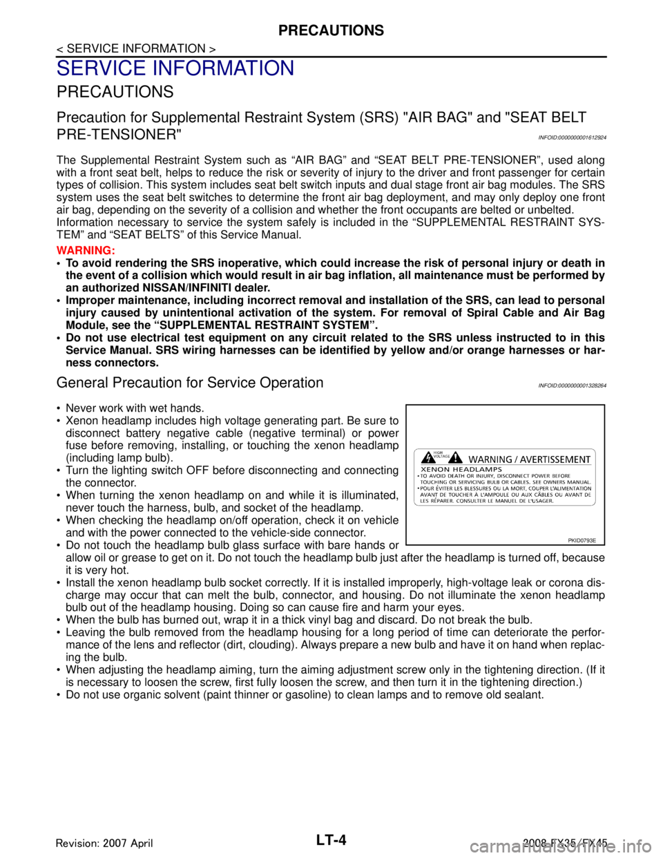
General Precaution for Service OperationINFOID:0000000001328264
Never work with wet hands.
Xenon headlamp includes high voltage generating part. Be sure to disconnect battery negative cable (negative terminal) or power
fuse before removing, installing, or touching the xenon headlamp
(including lamp bulb).
Turn the lighting switch OFF before disconnecting and connecting the connector.
When turning the xenon headlamp on and while it is illuminated, never touch the harness, bulb, and socket of the headlamp.
When checking the headlamp on/off operation, check it on vehicle
and with the power connected to the vehicle-side connector.
Do not touch the headlamp bulb glass surface with bare hands or allow oil or grease to get on it. Do not touch the headl amp bulb just after the headlamp is turned off, because
it is very hot.
Install the xenon headlamp bulb socket co rrectly. If it is installed improperly, high-voltage leak or corona dis-
charge may occur that can melt the bulb, connecto r, and housing. Do not illuminate the xenon headlamp
bulb out of the headlamp housing. Doing so can cause fire and harm your eyes.
When the bulb has burned out, wrap it in a thick vinyl bag and discard. Do not break the bulb.
Leaving the bulb removed from the headlamp housing for a long period of time can deteriorate the perfor- mance of the lens and reflector (dirt, clouding). Al ways prepare a new bulb and have it on hand when replac-
ing the bulb.
When adjusting the headlamp aiming, turn the aiming adjus tment screw only in the tightening direction. (If it
is necessary to loosen the screw, first fully loosen the screw, and then turn it in the tightening direction.)
Do not use organic solvent (paint thinner or gasoline) to clean lamps and to remove old sealant.
PKID0793E
3AA93ABC3ACD3AC03ACA3AC03AC63AC53A913A773A893A873A873A8E3A773A983AC73AC93AC03AC3
3A893A873A873A8F3A773A9D3AAF3A8A3A8C3A863A9D3AAF3A8B3A8C
Page 3121 of 3924
HEADLAMP - XENON TYPE -LT-19
< SERVICE INFORMATION >
C
DE
F
G H
I
J
L
M A
B
LT
N
O P
CONSULT-III DATA MONITOR
1. Select “HL LO REQ” and “HL HI RE Q” of IPDM E/R data monitor item.
2. With operating the lighting switch, check the monitor status
OK or NG
OK >> Replace IPDM E/R. Refer to PG-24, "Removal and Installation of IPDM E/R".
NG >> Replace BCM. Refer to BCS-13, "
Removal and Installation of BCM".
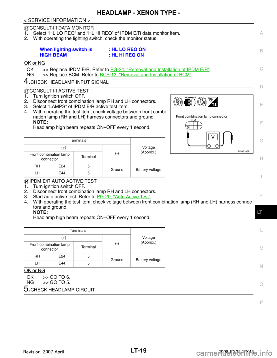
4.CHECK HEADLAMP INPUT SIGNAL
CONSULT-III ACTIVE TEST
1. Turn ignition switch OFF.
2. Disconnect front combination lamp RH and LH connectors.
3. Select “LAMPS” of IPDM E/R active test item
4. With operating the test item, check voltage between front combi- nation lamp (RH and LH) harness connectors and ground.
NOTE:
Headlamp high beam repeats ON–OFF every 1 second.
IPDM E/R AUTO ACTIVE TEST
1. Turn ignition switch OFF.
2. Disconnect front combination lamp RH and LH connectors.
3. Start auto active test. Refer to PG-20, "
Auto Active Test".
4. With operating the test item, check voltage betw een front combination lamp (RH and LH) harness connec-
tors and ground.
NOTE:
Headlamp high beam repeats ON–OFF every 1 second.
OK or NG
OK >> GO TO 6.
NG >> GO TO 5.
5.CHECK HEADLAMP CIRCUIT When lighting switch is
HIGH BEAM
: HL LO REQ ON
: HL HI REQ ON
Te r m i n a l s
Voltag e
(Approx.)
(+)
(-)
Front combination lamp
connector Te r m i n a l
RH E24 5 Ground Battery voltage
LH E44 5
Te r m i n a l s Voltag e
(Approx.)
(+)
(-)
Front combination lamp
connector Te r m i n a l
RH E24 5 Ground Battery voltage
LH E44 5
PKIA5205E
3AA93ABC3ACD3AC03ACA3AC03AC63AC53A913A773A893A873A873A8E3A773A983AC73AC93AC03AC3
3A893A873A873A8F3A773A9D3AAF3A8A3A8C3A863A9D3AAF3A8B3A8C
Page 3122 of 3924
LT-20
< SERVICE INFORMATION >
HEADLAMP - XENON TYPE -
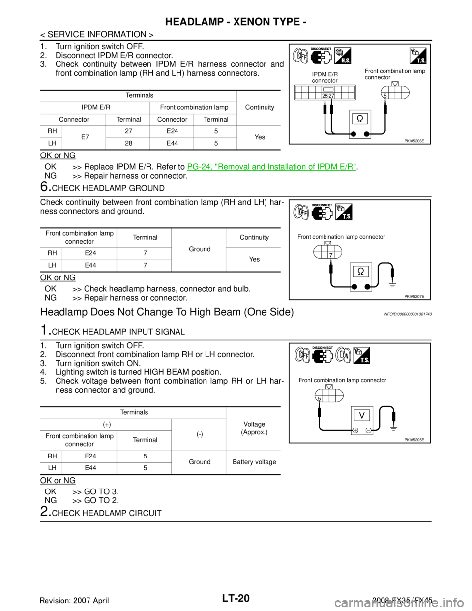
1. Turn ignition switch OFF.
2. Disconnect IPDM E/R connector.
3. Check continuity between IPDM E/R harness connector andfront combination lamp (RH and LH) harness connectors.
OK or NG
OK >> Replace IPDM E/R. Refer to PG-24, "Removal and Installation of IPDM E/R".
NG >> Repair harness or connector.
6.CHECK HEADLAMP GROUND
Check continuity between front combination lamp (RH and LH) har-
ness connectors and ground.
OK or NG
OK >> Check headlamp harness, connector and bulb.
NG >> Repair harness or connector.
Headlamp Does Not Change To High Beam (One Side)INFOID:0000000001381743
1.CHECK HEADLAMP INPUT SIGNAL
1. Turn ignition switch OFF.
2. Disconnect front combination lamp RH or LH connector.
3. Turn ignition switch ON.
4. Lighting switch is turned HIGH BEAM position.
5. Check voltage between front combination lamp RH or LH har- ness connector and ground.
OK or NG
OK >> GO TO 3.
NG >> GO TO 2.
2.CHECK HEADLAMP CIRCUIT
Te r m i n a l s Continuity
IPDM E/R Front combination lamp
Connector Terminal Connector Terminal
RH E7 27 E24 5
Ye s
LH 28 E44 5
PKIA5206E
Front combination lamp
connector Te r m i n a l
Ground Continuity
RH E24 7 Ye s
LH E44 7
PKIA5207E
Te r m i n a l s
Vo l ta g e
(Approx.)
(+)
(-)
Front combination lamp
connector Te r m i n a l
RH E24 5 Ground Battery voltage
LH E44 5
PKIA5205E
3AA93ABC3ACD3AC03ACA3AC03AC63AC53A913A773A893A873A873A8E3A773A983AC73AC93AC03AC3
3A893A873A873A8F3A773A9D3AAF3A8A3A8C3A863A9D3AAF3A8B3A8C
Page 3123 of 3924
HEADLAMP - XENON TYPE -LT-21
< SERVICE INFORMATION >
C
DE
F
G H
I
J
L
M A
B
LT
N
O P
1. Turn ignition switch OFF.
2. Disconnect IPDM E/R connector.
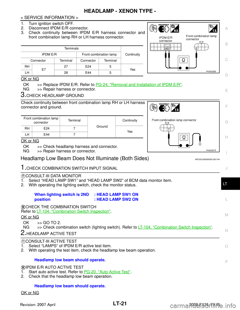
3. Check continuity between IPDM E/R harness connector and front combination lamp RH or LH harness connector.
OK or NG
OK >> Replace IPDM E/R. Refer to PG-24, "Removal and Installation of IPDM E/R".
NG >> Repair harness or connector.
3.CHECK HEADLAMP GROUND
Check continuity between front combination lamp RH or LH harness
connector and ground.
OK or NG
OK >> Check headlamp harness and connector.
NG >> Repair harness or connector.
Headlamp Low Beam Does No t Illuminate (Both Sides)INFOID:0000000001381744
1.CHECK COMBINATION SWITCH INPUT SIGNAL
CONSULT-III DATA MONITOR
1. Select “HEAD LAMP SW1” and “HEAD LA MP SW2” of BCM data monitor item.
2. With operating the lighting switch, check the monitor status.
CHECK THE COMBINATION SWITCH
Refer to LT-104, "
Combination Switch Inspection".
OK or NG
OK >> GO TO 2.
NG >> Check combination switch (lighting switch). Refer to LT-104, "
Combination Switch Inspection".
2.HEADLAMP ACTIVE TEST
CONSULT-III ACTIVE TEST
1. Select “LAMPS” of IPDM E/R active test item.
2. With operating the test item, check the headlamp low beam operation.
IPDM E/R AUTO ACTIVE TEST
1. Start auto active test. Refer to PG-20, "
Auto Active Test".
2. Check that the headlamp low beam operation.
OK or NG
Te r m i n a l s
Continuity
IPDM E/R Front combination lamp
Connector Terminal Connector Terminal
RH E7 27 E24 5
Ye s
LH 28 E44 5
PKIA5206E
Front combination lamp
connector Terminal
Ground Continuity
RH E24 7 Ye s
LH E44 7
PKIA5207E
When lighting switch is 2ND
position : HEAD LAMP SW1 ON
: HEAD LAMP SW2 ON
Headlamp low beam should operate.
Headlamp low beam should operate.
3AA93ABC3ACD3AC03ACA3AC03AC63AC53A913A773A893A873A873A8E3A773A983AC73AC93AC03AC3
3A893A873A873A8F3A773A9D3AAF3A8A3A8C3A863A9D3AAF3A8B3A8C