Page 3217 of 3924
STOP LAMPLT-115
< SERVICE INFORMATION >
C
DE
F
G H
I
J
L
M A
B
LT
N
O P
1. Remove cap from back door finisher and remove nuts. Refer to EI-47, "
Component Parts Location".
2. Disconnect high-mounted stop lamp connector.
3. Remove washer tube from high-mounted stop lamp, and remove high-mounted stop lamp from the rear air spoiler.
4. Remove seal packing from the rear air spoiler.
5. Installation is the reverse order of removal.
CAUTION:
Seal packing cannot be reused.
Stop LampINFOID:0000000001328377
BULB REPLACEMENT
Refer to LT-137, "Bulb Replacement".
REMOVAL AND INSTALLATION
Refer to LT-137, "Removal and Installation".
Rear Combination Lamp Control UnitINFOID:0000000001328378
REMOVAL AND INSTALLATION
Refer to LT-95, "Removal and Installation of Rear Combination Lamp Control Unit".
High-mounted stop lamp : LED
SKIA5562E
3AA93ABC3ACD3AC03ACA3AC03AC63AC53A913A773A893A873A873A8E3A773A983AC73AC93AC03AC3
3A893A873A873A8F3A773A9D3AAF3A8A3A8C3A863A9D3AAF3A8B3A8C
Page 3219 of 3924
BACK-UP LAMPLT-117
< SERVICE INFORMATION >
C
DE
F
G H
I
J
L
M A
B
LT
N
O P
Bulb ReplacementINFOID:0000000001328380
1. Remove rear combination lamp (back door side).
2. Turn bulb socket counterclockwise and unlock it.
3. Remove bulb.
Removal and InstallationINFOID:0000000001328381
1. Remove back door finisher. Refer to EI-47, "Component Parts
Location".
2. Disconnect rear combination lamp connector.
3. Remove rear combination lamp mounting nuts.
4. Remove rear combination lamp from back door.
5. Remove seal packing from back door. Back-up lamp : 12 V - 18 W
PKIB3634E
PKIB3635E
3AA93ABC3ACD3AC03ACA3AC03AC63AC53A913A773A893A873A873A8E3A773A983AC73AC93AC03AC3
3A893A873A873A8F3A773A9D3AAF3A8A3A8C3A863A9D3AAF3A8B3A8C
Page 3232 of 3924
LT-130
< SERVICE INFORMATION >
PARKING, LICENSE PLATE AND TAIL LAMPS
2.ACTIVE TEST
CONSULT-III ACTIVE TEST
1. Select “TAIL LAMP” of IPDM E/R active test item.
2. With operating the test item, check the parking, license plate, side marker and tail lamps operation.
IPDM E/R AUTO ACTIVE TEST
1. Start auto active test. Refer to PG-20, "
Auto Active Test".
2. Check that the parking, license plate, side marker and tail lamps operation.
OK or NG
OK >> GO TO 3.
NG >> GO TO 4.
3.CHECK IPDM E/R
1. Select “TAIL&CLR REQ” of IPDM E/R data monitor item.
2. With operating the lighting switch, check the monitor status.
OK or NG
OK >> Replace IPDM E/R. Refer to PG-24, "Removal and Installation of IPDM E/R".
NG >> Replace BCM. Refer to BCS-13, "
Removal and Installation of BCM".
4.CHECK IPDM E/R
CONSULT-III ACTIVE TEST
1. Turn ignition switch OFF.
2. Disconnect front side marker lamp, parking lamp, license plate lamp and rear combination lamp connec- tors.
3. Select “TAIL LAMP” of IPDM E/R active test item.
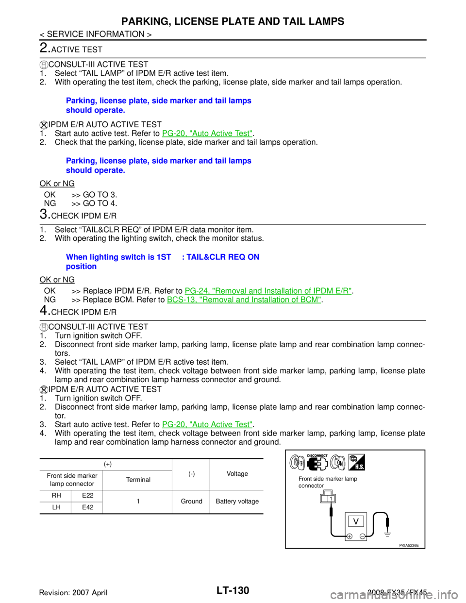
4. With operating the test item, check voltage between fr ont side marker lamp, parking lamp, license plate
lamp and rear combination lamp harness connector and ground.
IPDM E/R AUTO ACTIVE TEST
1. Turn ignition switch OFF.
2. Disconnect front side marker lamp, parking lamp, license plate lamp and rear combination lamp connec-
tor.
3. Start auto active test. Refer to PG-20, "
Auto Active Test".
4. With operating the test item, check voltage between fr ont side marker lamp, parking lamp, license plate
lamp and rear combination lamp harness connector and ground. Parking, license plate, side marker and tail lamps
should operate.
Parking, license plate, side marker and tail lamps
should operate.
When lighting switch is 1ST
position
: TAIL&CLR REQ ON
(+)
(-) Voltage
Front side marker
lamp connector Te r m i n a l
RH E22 1 Ground Battery voltage
LH E42
PKIA5236E
3AA93ABC3ACD3AC03ACA3AC03AC63AC53A913A773A893A873A873A8E3A773A983AC73AC93AC03AC3
3A893A873A873A8F3A773A9D3AAF3A8A3A8C3A863A9D3AAF3A8B3A8C
Page 3234 of 3924
LT-132
< SERVICE INFORMATION >
PARKING, LICENSE PLATE AND TAIL LAMPS
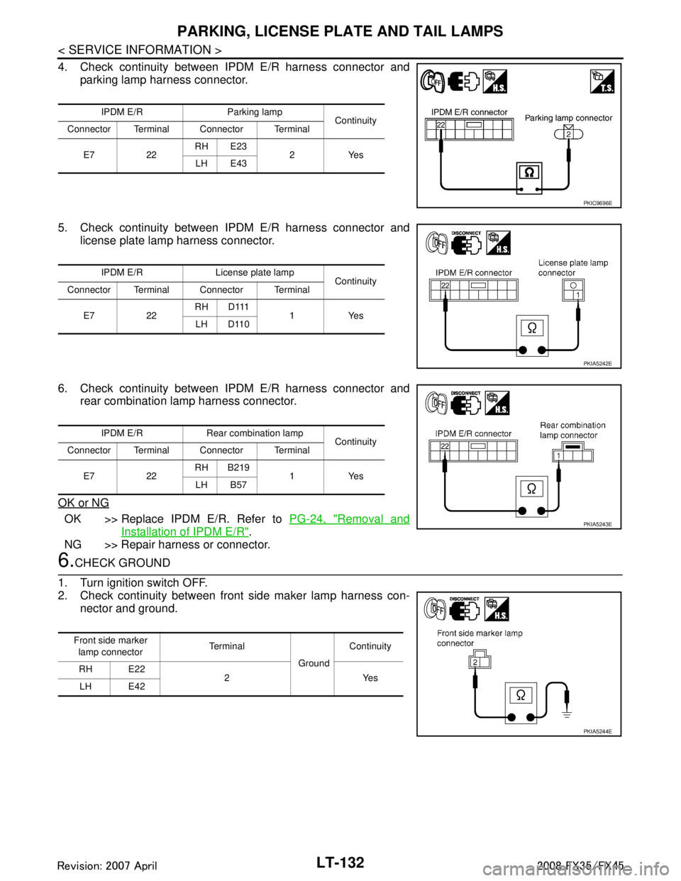
4. Check continuity between IPDM E/R harness connector andparking lamp harness connector.
5. Check continuity between IPDM E/R harness connector and license plate lamp harness connector.
6. Check continuity between IPDM E/R harness connector and rear combination lamp harness connector.
OK or NG
OK >> Replace IPDM E/R. Refer to PG-24, "Removal and
Installation of IPDM E/R".
NG >> Repair harness or connector.
6.CHECK GROUND
1. Turn ignition switch OFF.
2. Check continuity between front side maker lamp harness con- nector and ground.
IPDM E/R Parking lamp Continuity
Connector Terminal Connector Terminal
E7 22 RH E23
2Yes
LH E43
PKIC9696E
IPDM E/R License plate lamp Continuity
Connector Terminal Connector Terminal
E7 22 RH D111
1Yes
LH D110
PKIA5242E
IPDM E/R Rear combination lamp Continuity
Connector Terminal Connector Terminal
E7 22 RH B219
1Yes
LH B57
PKIA5243E
Front side marker
lamp connector Te r m i n a l
GroundContinuity
RH E22 2Yes
LH E42
PKIA5244E
3AA93ABC3ACD3AC03ACA3AC03AC63AC53A913A773A893A873A873A8E3A773A983AC73AC93AC03AC3
3A893A873A873A8F3A773A9D3AAF3A8A3A8C3A863A9D3AAF3A8B3A8C
Page 3237 of 3924
PARKING, LICENSE PLATE AND TAIL LAMPS
LT-135
< SERVICE INFORMATION >
C
D E
F
G H
I
J
L
M A
B
LT
N
O P
Minutes)INFOID:0000000001328397
1.CHECK IPDM E/R
1. Turn ignition switch ON. Turn combination switch (li ghting switch) to the OFF position. Turn ignition switch
OFF.
2. Verify that parking, license plate, and tail lamps turn on and off after approximately 10 minutes.
OK or NG
OK >> Ignition relay malfunction. Refer to PG-18, "Function of Detecting Ignition Relay Malfunction".
NG >> INSPECTION END
License Plate LampINFOID:0000000001328398
BULB REPLACEMENT, REMOVAL AND INSTALLATION
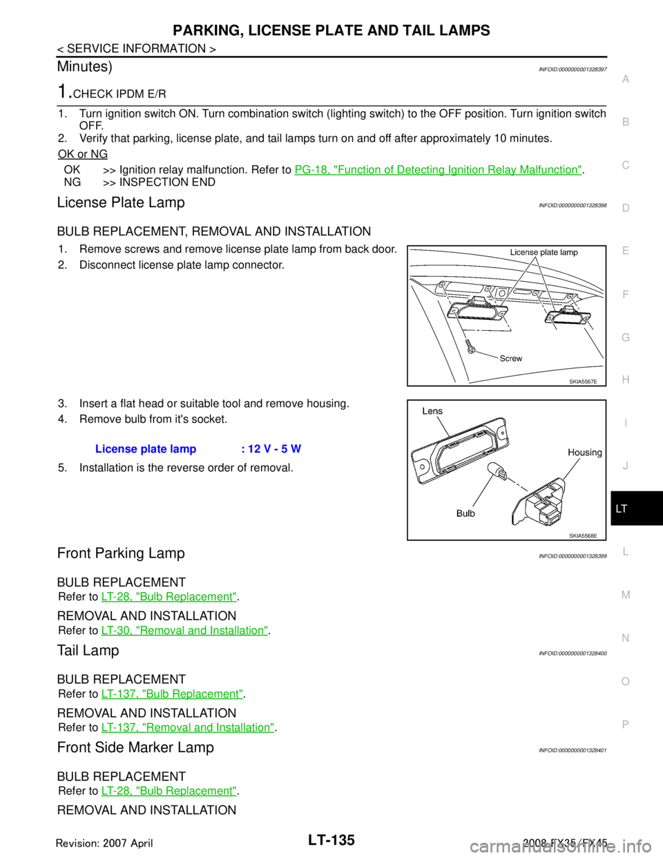
1. Remove screws and remove license plate lamp from back door.
2. Disconnect license plate lamp connector.
3. Insert a flat head or suitable tool and remove housing.
4. Remove bulb from it's socket.
5. Installation is the reverse order of removal.
Front Parking LampINFOID:0000000001328399
BULB REPLACEMENT
Refer to LT-28, "Bulb Replacement".
REMOVAL AND INSTALLATION
Refer to LT-30, "Removal and Installation".
Ta i l L a m pINFOID:0000000001328400
BULB REPLACEMENT
Refer to LT-137, "Bulb Replacement".
REMOVAL AND INSTALLATION
Refer to LT-137, "Removal and Installation".
Front Side Marker LampINFOID:0000000001328401
BULB REPLACEMENT
Refer to LT-28, "Bulb Replacement".
REMOVAL AND INSTALLATION
SKIA5567E
License plate lamp : 12 V - 5 W
SKIA5568E
3AA93ABC3ACD3AC03ACA3AC03AC63AC53A913A773A893A873A873A8E3A773A983AC73AC93AC03AC3
3A893A873A873A8F3A773A9D3AAF3A8A3A8C3A863A9D3AAF3A8B3A8C
Page 3238 of 3924
LT-136
< SERVICE INFORMATION >
PARKING, LICENSE PLATE AND TAIL LAMPS
Refer to LT-30, "Removal and Installation".
Rear Side Marker LampINFOID:0000000001328402
BULB REPLACEMENT
Refer to LT-137, "Bulb Replacement".
REMOVAL AND INSTALLATION
Refer to LT-137, "Removal and Installation".
Rear Combination Lamp Control UnitINFOID:0000000001328403
REMOVAL AND INSTALLATION
Refer to LT-95, "Removal and Installation of Rear Combination Lamp Control Unit".
3AA93ABC3ACD3AC03ACA3AC03AC63AC53A913A773A893A873A873A8E3A773A983AC73AC93AC03AC3
3A893A873A873A8F3A773A9D3AAF3A8A3A8C3A863A9D3AAF3A8B3A8C
Page 3239 of 3924
REAR COMBINATION LAMPLT-137
< SERVICE INFORMATION >
C
DE
F
G H
I
J
L
M A
B
LT
N
O P
REAR COMBINATION LAMP
Bulb ReplacementINFOID:0000000001328404
REAR FENDER SIDE (REAR SIDE MARKER LAMP BULB)
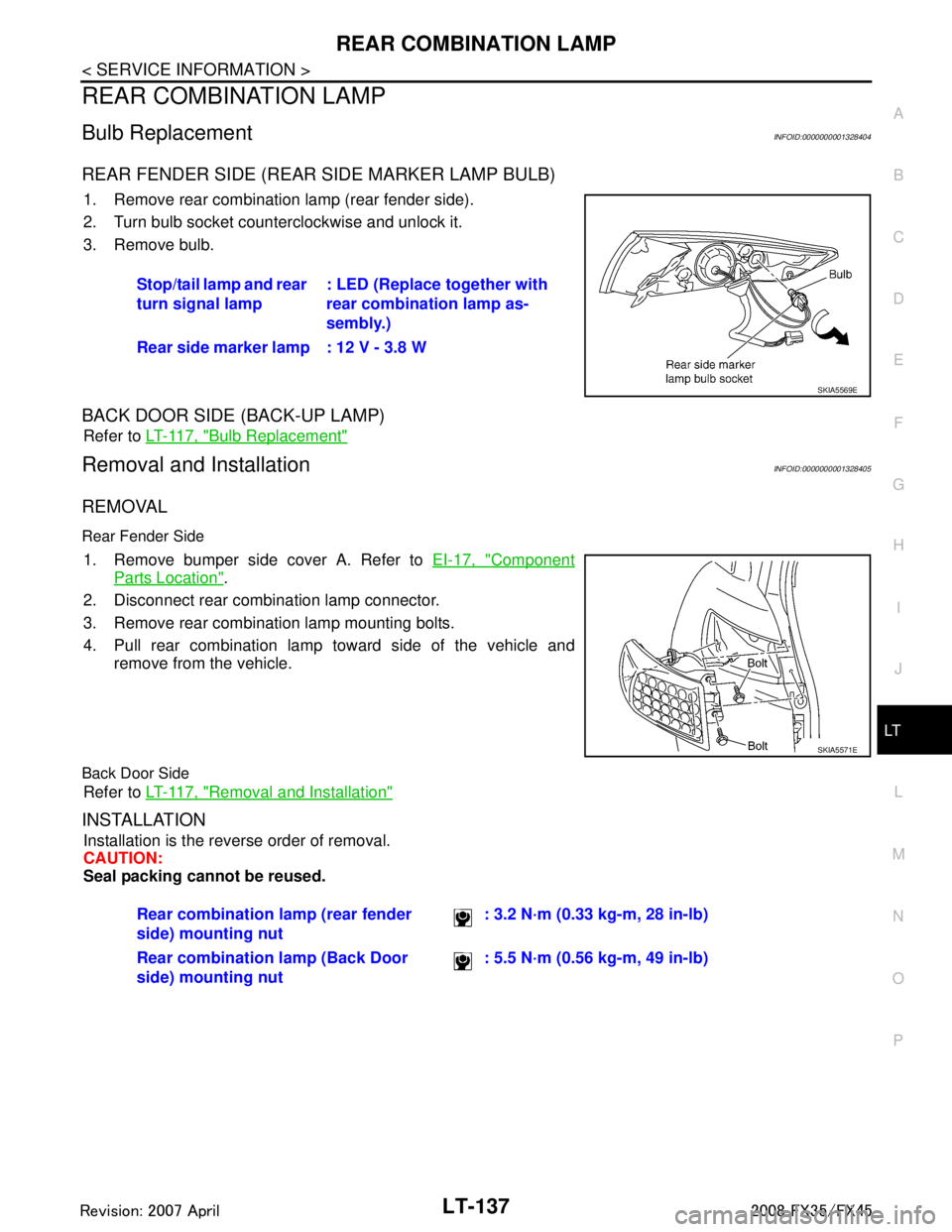
1. Remove rear combination lamp (rear fender side).
2. Turn bulb socket counterclockwise and unlock it.
3. Remove bulb.
BACK DOOR SIDE (BACK-UP LAMP)
Refer to LT-117, "Bulb Replacement"
Removal and InstallationINFOID:0000000001328405
REMOVAL
Rear Fender Side
1. Remove bumper side cover A. Refer to EI-17, "Component
Parts Location".
2. Disconnect rear combination lamp connector.
3. Remove rear combination lamp mounting bolts.
4. Pull rear combination lamp toward side of the vehicle and remove from the vehicle.
Back Door Side
Refer to LT-117, "Removal and Installation"
INSTALLATION
Installation is the reverse order of removal.
CAUTION:
Seal packing cannot be reused.Stop/tail lamp and rear
turn signal lamp
: LED (Replace together with
rear combination lamp as-
sembly.)
Rear side marker lamp : 12 V - 3.8 W
SKIA5569E
SKIA5571E
Rear combination lamp (rear fender
side) mounting nut : 3.2 N·m (0.33 kg-m, 28 in-lb)
Rear combination lamp (Back Door
side) mounting nut : 5.5 N·m (0.56 kg-m, 49 in-lb)
3AA93ABC3ACD3AC03ACA3AC03AC63AC53A913A773A893A873A873A8E3A773A983AC73AC93AC03AC3
3A893A873A873A8F3A773A9D3AAF3A8A3A8C3A863A9D3AAF3A8B3A8C
Page 3260 of 3924
LT-158
< SERVICE INFORMATION >
INTERIOR ROOM LAMP
OK >> Replace BCM. Refer to BCS-13, "Removal and Installation of BCM".
NG >> GO TO 3.
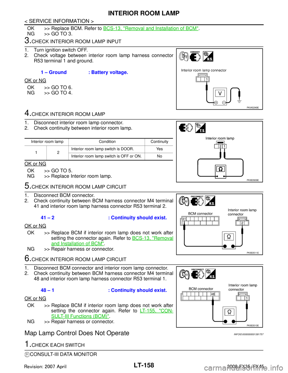
3.CHECK INTERIOR ROOM LAMP INPUT
1. Turn ignition switch OFF.
2. Check voltage between interior room lamp harness connector R53 terminal 1 and ground.
OK or NG
OK >> GO TO 6.
NG >> GO TO 4.
4.CHECK INTERIOR ROOM LAMP
1. Disconnect interior room lamp connector.
2. Check continuity between interior room lamp.
OK or NG
OK >> GO TO 5.
NG >> Replace Interior room lamp.
5.CHECK INTERIOR ROOM LAMP CIRCUIT
1. Disconnect BCM connector.
2. Check continuity between BCM harness connector M4 terminal 41 and interior room lamp harness connector R53 terminal 2.
OK or NG
OK >> Replace BCM if interior room lamp does not work after setting the connector again. Refer to BCS-13, "
Removal
and Installation of BCM".
NG >> Repair harness or connector.
6.CHECK INTERIOR ROOM LAMP CIRCUIT
1. Disconnect BCM connector and interior room lamp connector.
2. Check continuity between BCM harness connector M4 terminal 48 and interior room lamp harness connector R53 terminal 1.
OK or NG
OK >> Replace BCM if interior room lamp does not work after setting the connector again. Refer to LT-155, "
CON-
SULT-III Functions (BCM)".
NG >> Repair harness or connector.
Map Lamp Control Does Not OperateINFOID:0000000001381757
1.CHECK EACH SWITCH
CONSULT-III DATA MONITOR 1 – Ground : Battery voltage.
PKIA5249E
Interior room lamp Condition Continuity
12 Interior room lamp switch is DOOR. Yes
Interior room lamp switch is OFF or ON. No
PKIB3509E
41 – 2 : Continuity should exist.
PKIB3511E
48 – 1 : Continuity should exist.
PKIB3510E
3AA93ABC3ACD3AC03ACA3AC03AC63AC53A913A773A893A873A873A8E3A773A983AC73AC93AC03AC3
3A893A873A873A8F3A773A9D3AAF3A8A3A8C3A863A9D3AAF3A8B3A8C