2008 INFINITI FX35 installation
[x] Cancel search: installationPage 3261 of 3924
INTERIOR ROOM LAMPLT-159
< SERVICE INFORMATION >
C
DE
F
G H
I
J
L
M A
B
LT
N
O P
1. Select “INT LAMP” of BCM data monitor item.
2. Check that switches listed in display item list turn ON-OFF linked with switch operation. Refer to LT-155,
"CONSULT-III Functions (BCM)" for switches and their functions.
OK or NG
OK >> GO TO 2.
NG >> Inspect malfunctioning switch system.
2.CHECK BETWEEN BC M AND MAP LAMP
CONSULT-III ACTIVE TEST
1. Select “INT LAMP” of BCM (INT LAMP) active test item.
2. With operating the test item, check the map lamp oper ation (When map lamp switch is in DOOR position).
OK or NG
OK >> Replace BCM. Refer to BCS-13, "Removal and Installation of BCM".
NG >> GO TO 3.
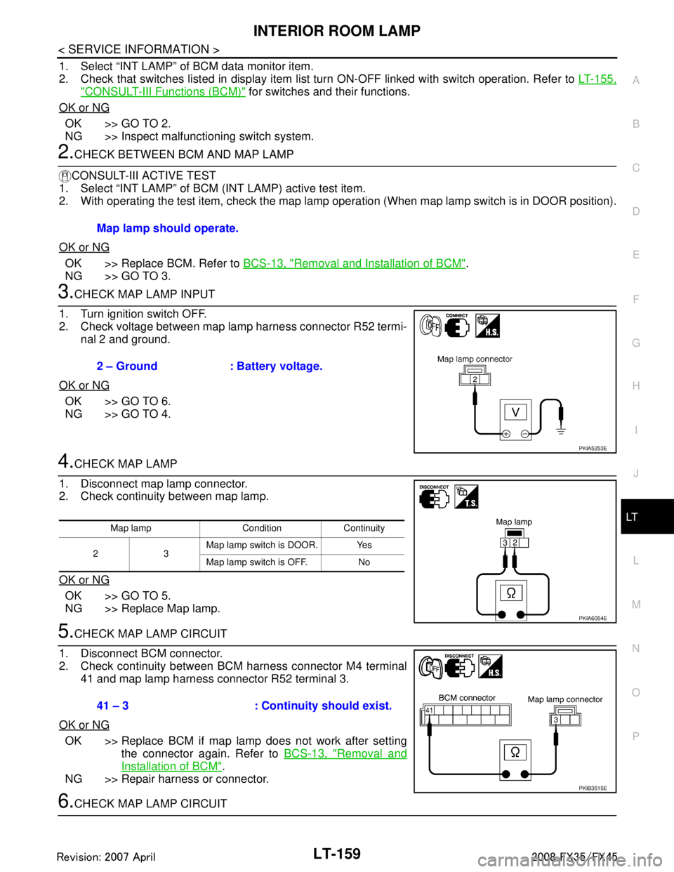
3.CHECK MAP LAMP INPUT
1. Turn ignition switch OFF.
2. Check voltage between map lamp harness connector R52 termi- nal 2 and ground.
OK or NG
OK >> GO TO 6.
NG >> GO TO 4.
4.CHECK MAP LAMP
1. Disconnect map lamp connector.
2. Check continuity between map lamp.
OK or NG
OK >> GO TO 5.
NG >> Replace Map lamp.
5.CHECK MAP LAMP CIRCUIT
1. Disconnect BCM connector.
2. Check continuity between BCM harness connector M4 terminal 41 and map lamp harness connector R52 terminal 3.
OK or NG
OK >> Replace BCM if map lamp does not work after setting the connector again. Refer to BCS-13, "
Removal and
Installation of BCM".
NG >> Repair harness or connector.
6.CHECK MAP LAMP CIRCUIT Map lamp should operate.
2 – Ground : Battery voltage.
PKIA5253E
Map lamp Condition Continuity
23 Map lamp switch is DOOR. Yes
Map lamp switch is OFF. No
PKIA6054E
41 – 3 : Continui
ty should exist.
PKIB3515E
3AA93ABC3ACD3AC03ACA3AC03AC63AC53A913A773A893A873A873A8E3A773A983AC73AC93AC03AC3
3A893A873A873A8F3A773A9D3AAF3A8A3A8C3A863A9D3AAF3A8B3A8C
Page 3262 of 3924
LT-160
< SERVICE INFORMATION >
INTERIOR ROOM LAMP
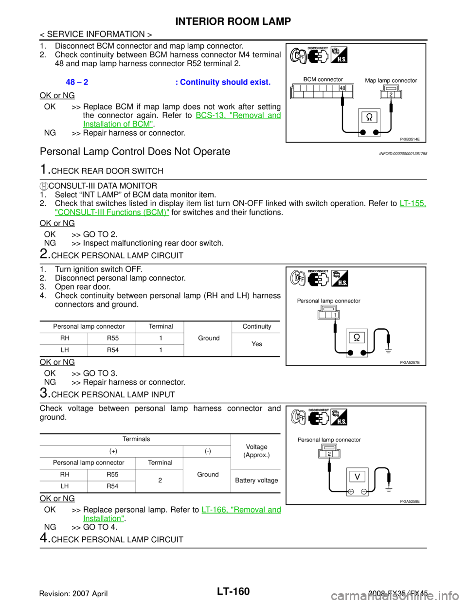
1. Disconnect BCM connector and map lamp connector.
2. Check continuity between BCM harness connector M4 terminal48 and map lamp harness connector R52 terminal 2.
OK or NG
OK >> Replace BCM if map lamp does not work after setting the connector again. Refer to BCS-13, "
Removal and
Installation of BCM".
NG >> Repair harness or connector.
Personal Lamp Control Does Not OperateINFOID:0000000001381758
1.CHECK REAR DOOR SWITCH
CONSULT-III DATA MONITOR
1. Select “INT LAMP” of BCM data monitor item.
2. Check that switches listed in display item list turn ON-OFF linked with switch operation. Refer to LT-155,
"CONSULT-III Functions (BCM)" for switches and their functions.
OK or NG
OK >> GO TO 2.
NG >> Inspect malfunctioning rear door switch.
2.CHECK PERSONAL LAMP CIRCUIT
1. Turn ignition switch OFF.
2. Disconnect personal lamp connector.
3. Open rear door.
4. Check continuity between personal lamp (RH and LH) harness connectors and ground.
OK or NG
OK >> GO TO 3.
NG >> Repair harness or connector.
3.CHECK PERSONAL LAMP INPUT
Check voltage between personal lamp harness connector and
ground.
OK or NG
OK >> Replace personal lamp. Refer to LT-166, "Removal and
Installation".
NG >> GO TO 4.
4.CHECK PERSONAL LAMP CIRCUIT 48 – 2 : Continuity should exist.
PKIB3514E
Personal lamp connector Terminal
GroundContinuity
RH R55 1 Ye s
LH R54 1
PKIA5257E
Te r m i n a l s
Vo l ta g e
(Approx.)
(+) (-)
Personal lamp connector Terminal Ground
RH R55
2 Battery voltage
LH R54
PKIA5258E
3AA93ABC3ACD3AC03ACA3AC03AC63AC53A913A773A893A873A873A8E3A773A983AC73AC93AC03AC3
3A893A873A873A8F3A773A9D3AAF3A8A3A8C3A863A9D3AAF3A8B3A8C
Page 3263 of 3924
INTERIOR ROOM LAMPLT-161
< SERVICE INFORMATION >
C
DE
F
G H
I
J
L
M A
B
LT
N
O P
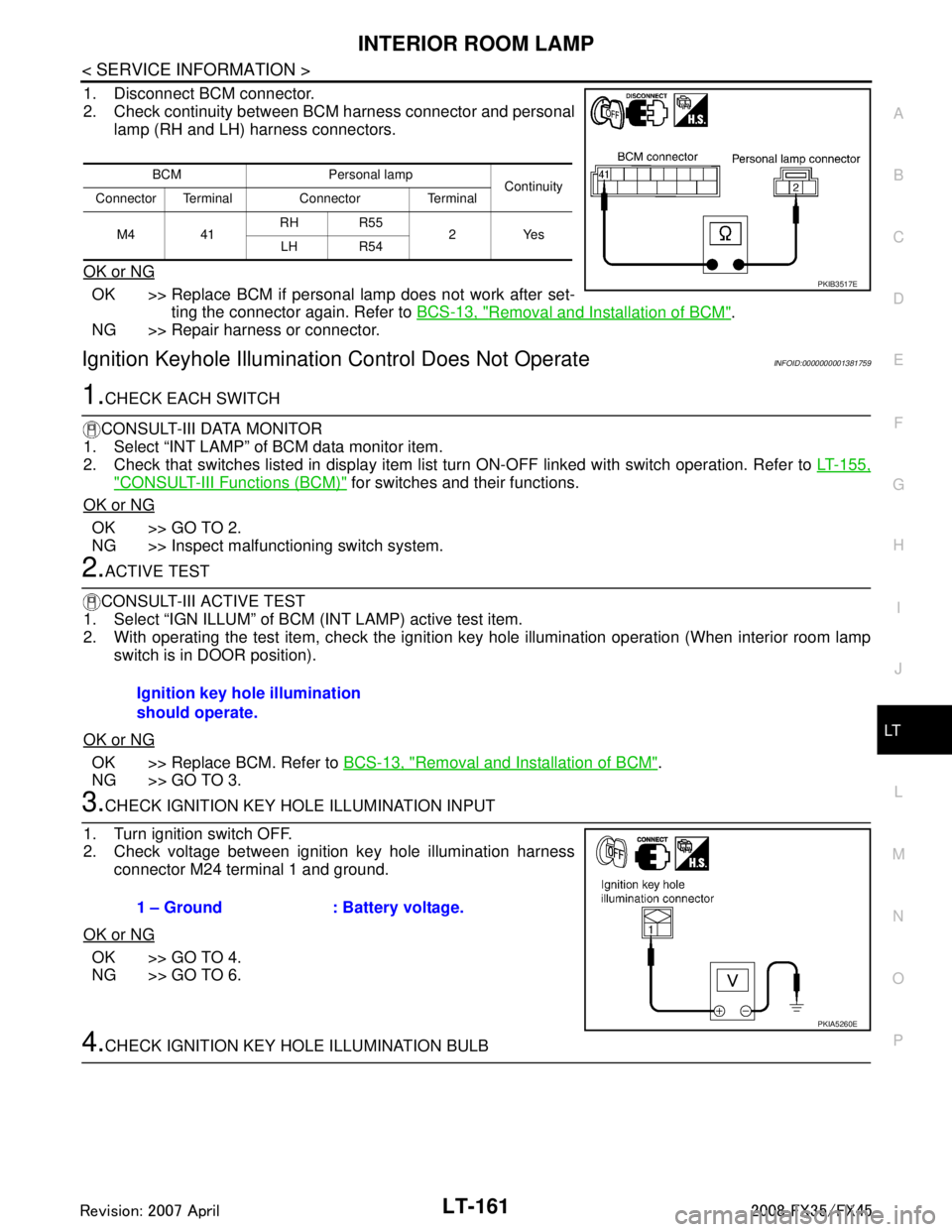
1. Disconnect BCM connector.
2. Check continuity between BCM harness connector and personal lamp (RH and LH) harness connectors.
OK or NG
OK >> Replace BCM if personal lamp does not work after set- ting the connector again. Refer to BCS-13, "
Removal and Installation of BCM".
NG >> Repair harness or connector.
Ignition Keyhole Illumination Control Does Not OperateINFOID:0000000001381759
1.CHECK EACH SWITCH
CONSULT-III DATA MONITOR
1. Select “INT LAMP” of BCM data monitor item.
2. Check that switches listed in display item list turn ON-OFF linked with switch operation. Refer to LT-155,
"CONSULT-III Functions (BCM)" for switches and their functions.
OK or NG
OK >> GO TO 2.
NG >> Inspect malfunctioning switch system.
2.ACTIVE TEST
CONSULT-III ACTIVE TEST
1. Select “IGN ILLUM” of BCM (INT LAMP) active test item.
2. With operating the test item, check the ignition ke y hole illumination operation (When interior room lamp
switch is in DOOR position).
OK or NG
OK >> Replace BCM. Refer to BCS-13, "Removal and Installation of BCM".
NG >> GO TO 3.
3.CHECK IGNITION KEY HOLE ILLUMINATION INPUT
1. Turn ignition switch OFF.
2. Check voltage between ignition key hole illumination harness connector M24 terminal 1 and ground.
OK or NG
OK >> GO TO 4.
NG >> GO TO 6.
4.CHECK IGNITION KEY HOLE ILLUMINATION BULB
BCM Personal lamp Continuity
Connector Terminal Connector Terminal
M4 41 RH R55
2Yes
LH R54
PKIB3517E
Ignition key hole illumination
should operate.
1 – Ground : Battery voltage.
PKIA5260E
3AA93ABC3ACD3AC03ACA3AC03AC63AC53A913A773A893A873A873A8E3A773A983AC73AC93AC03AC3
3A893A873A873A8F3A773A9D3AAF3A8A3A8C3A863A9D3AAF3A8B3A8C
Page 3264 of 3924
LT-162
< SERVICE INFORMATION >
INTERIOR ROOM LAMP
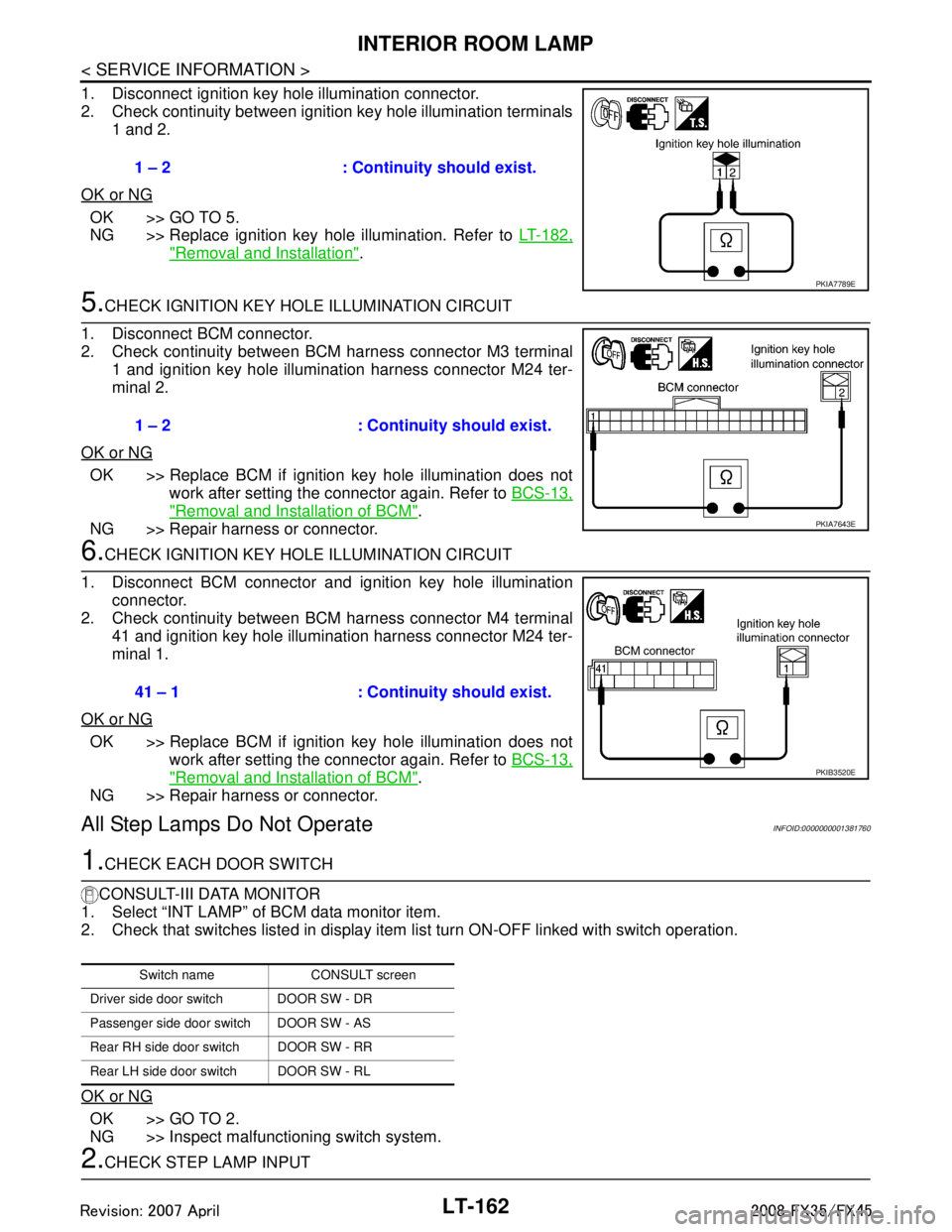
1. Disconnect ignition key hole illumination connector.
2. Check continuity between ignition key hole illumination terminals1 and 2.
OK or NG
OK >> GO TO 5.
NG >> Replace ignition key hole illumination. Refer to LT-182,
"Removal and Installation".
5.CHECK IGNITION KEY HOLE ILLUMINATION CIRCUIT
1. Disconnect BCM connector.
2. Check continuity between BCM harness connector M3 terminal 1 and ignition key hole illumination harness connector M24 ter-
minal 2.
OK or NG
OK >> Replace BCM if ignition key hole illumination does not work after setting the connector again. Refer to BCS-13,
"Removal and Installation of BCM".
NG >> Repair harness or connector.
6.CHECK IGNITION KEY HOLE ILLUMINATION CIRCUIT
1. Disconnect BCM connector and ignition key hole illumination connector.
2. Check continuity between BCM harness connector M4 terminal
41 and ignition key hole illumination harness connector M24 ter-
minal 1.
OK or NG
OK >> Replace BCM if ignition key hole illumination does not work after setting the connector again. Refer to BCS-13,
"Removal and Installation of BCM".
NG >> Repair harness or connector.
All Step Lamps Do Not OperateINFOID:0000000001381760
1.CHECK EACH DOOR SWITCH
CONSULT-III DATA MONITOR
1. Select “INT LAMP” of BCM data monitor item.
2. Check that switches listed in display item list turn ON-OFF linked with switch operation.
OK or NG
OK >> GO TO 2.
NG >> Inspect malfunctioning switch system.
2.CHECK STEP LAMP INPUT 1 – 2 : Continuity should exist.
PKIA7789E
1 – 2 : Continuity should exist.
PKIA7643E
41 – 1 : Continuity should exist.
PKIB3520E
Switch name CONSULT screen
Driver side door switch DOOR SW - DR
Passenger side door switch DOOR SW - AS
Rear RH side door switch DOOR SW - RR
Rear LH side door switch DOOR SW - RL
3AA93ABC3ACD3AC03ACA3AC03AC63AC53A913A773A893A873A873A8E3A773A983AC73AC93AC03AC3
3A893A873A873A8F3A773A9D3AAF3A8A3A8C3A863A9D3AAF3A8B3A8C
Page 3265 of 3924
INTERIOR ROOM LAMPLT-163
< SERVICE INFORMATION >
C
DE
F
G H
I
J
L
M A
B
LT
N
O P
1. Turn ignition switch OFF.
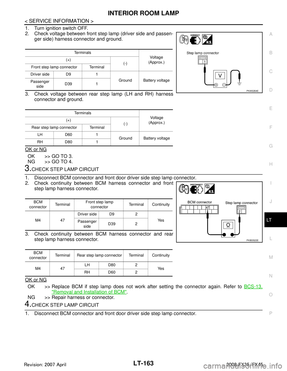
2. Check voltage between front step lamp (driver side and passen- ger side) harness connector and ground.
3. Check voltage between rear step lamp (LH and RH) harness connector and ground.
OK or NG
OK >> GO TO 3.
NG >> GO TO 4.
3.CHECK STEP LAMP CIRCUIT
1. Disconnect BCM connector and front door driver side step lamp connector.
2. Check continuity between BCM harness connector and front step lamp harness connector.
3. Check continuity between BCM harness connector and rear step lamp harness connector.
OK or NG
OK >> Replace BCM if step lamp does not work after setting the connector again. Refer to BCS-13,
"Removal and Installation of BCM".
NG >> Repair harness or connector.
4.CHECK STEP LAMP CIRCUIT
1. Disconnect BCM connector and front door driver side step lamp connector.
Te r m i n a l s Vo l ta g e
(Approx.)
(+)
(-)
Front step lamp connector Terminal
Driver side D9 1 Ground Battery voltage
Passenger
side D39 1
Te r m i n a l s Voltag e
(Approx.)
(+)
(-)
Rear step lamp connector Terminal
LH D60 1 Ground Battery voltage
RH D80 1
PKIA5264E
BCM
connector Te r m i n a l Front step lamp
connector Terminal Continuity
M4 47 Driver side D9 2
Ye s
Passenger
side D39 2
BCM
connector Terminal Rear step lamp connector Terminal Continuity
M4 47 LH D80 2
Ye s
RH D60 2
PKIB3522E
3AA93ABC3ACD3AC03ACA3AC03AC63AC53A913A773A893A873A873A8E3A773A983AC73AC93AC03AC3
3A893A873A873A8F3A773A9D3AAF3A8A3A8C3A863A9D3AAF3A8B3A8C
Page 3266 of 3924
LT-164
< SERVICE INFORMATION >
INTERIOR ROOM LAMP
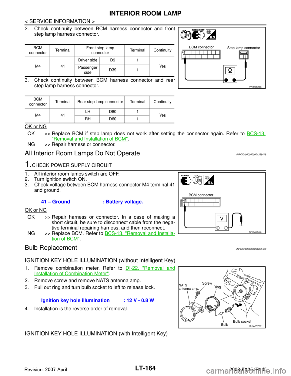
2. Check continuity between BCM harness connector and frontstep lamp harness connector.
3. Check continuity between BCM harness connector and rear step lamp harness connector.
OK or NG
OK >> Replace BCM if step lamp does not work after setting the connector again. Refer to BCS-13,
"Removal and Installation of BCM".
NG >> Repair harness or connector.
All Interior Room La mps Do Not OperateINFOID:0000000001328419
1.CHECK POWER SUPPLY CIRCUIT
1. All interior room lamps switch are OFF.
2. Turn ignition switch ON.
3. Check voltage between BCM harness connector M4 terminal 41 and ground.
OK or NG
OK >> Repair harness or connector. In a case of making a short circuit, be sure to disconnect cable from the nega-
tive terminal repairing harness, and then reconnect.
NG >> Replace BCM. Refer to BCS-13, "
Removal and Installa-
tion of BCM".
Bulb ReplacementINFOID:0000000001328420
IGNITION KEY HOLE ILLUMINATION (without Intelligent Key)
1. Remove combination meter. Refer to DI-22, "Removal and
Installation of Combination Meter".
2. Remove screw and remove NATS antenna amp.
3. Pull out ring and turn bulb socket to left to release lock.
4. Installation is the reverse order of removal.
IGNITION KEY HOLE ILLUMINA TION (with Intelligent Key)
BCM
connector Te r m i n a l Front step lamp
connector Terminal Continuity
M4 41 Driver side D9 1
Ye s
Passenger
side D39 1
BCM
connector Terminal Rear step lamp connector Terminal Continuity
M4 41 LH D80 1
Ye s
RH D60 1
PKIB3523E
41 – Ground : Battery voltage.
SKIA5952E
Ignition key hole illu mination : 12 V - 0.8 W
SKIA5575E
3AA93ABC3ACD3AC03ACA3AC03AC63AC53A913A773A893A873A873A8E3A773A983AC73AC93AC03AC3
3A893A873A873A8F3A773A9D3AAF3A8A3A8C3A863A9D3AAF3A8B3A8C
Page 3267 of 3924
INTERIOR ROOM LAMPLT-165
< SERVICE INFORMATION >
C
DE
F
G H
I
J
L
M A
B
LT
N
O P
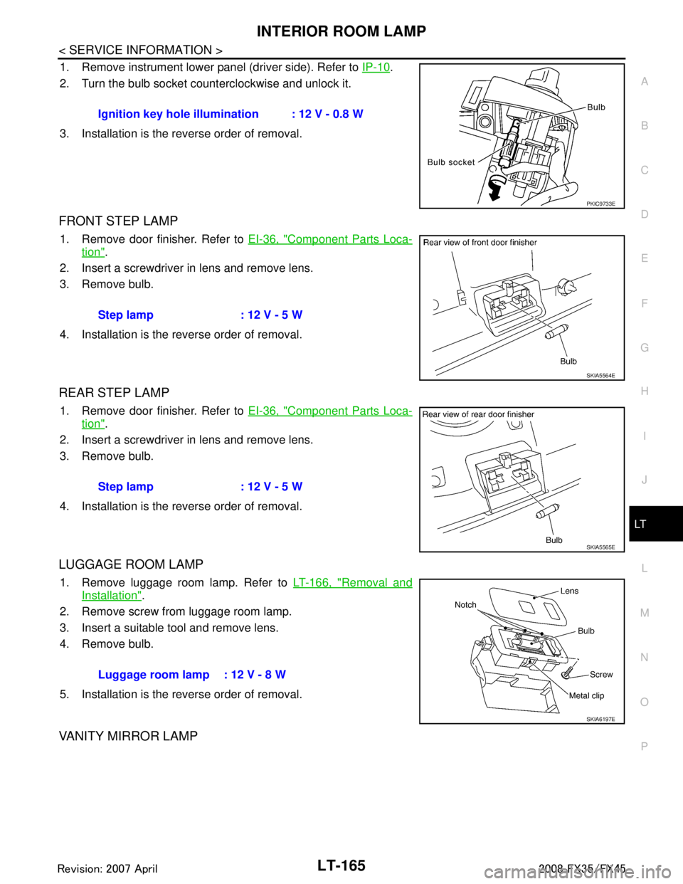
1. Remove instrument lower panel (driver side). Refer to IP-10.
2. Turn the bulb socket counterclockwise and unlock it.
3. Installation is the reverse order of removal.
FRONT STEP LAMP
1. Remove door finisher. Refer to EI-36, "Component Parts Loca-
tion".
2. Insert a screwdriver in lens and remove lens.
3. Remove bulb.
4. Installation is the reverse order of removal.
REAR STEP LAMP
1. Remove door finisher. Refer to EI-36, "Component Parts Loca-
tion".
2. Insert a screwdriver in lens and remove lens.
3. Remove bulb.
4. Installation is the reverse order of removal.
LUGGAGE ROOM LAMP
1. Remove luggage room lamp. Refer to LT-166, "Removal and
Installation".
2. Remove screw from luggage room lamp.
3. Insert a suitable tool and remove lens.
4. Remove bulb.
5. Installation is the reverse order of removal.
VANITY MIRROR LAMP
Ignition key hole illumination : 12 V - 0.8 W
PKIC9733E
Step lamp : 12 V - 5 W
SKIA5564E
Step lamp : 12 V - 5 W
SKIA5565E
Luggage room lamp : 12 V - 8 W
SKIA6197E
3AA93ABC3ACD3AC03ACA3AC03AC63AC53A913A773A893A873A873A8E3A773A983AC73AC93AC03AC3
3A893A873A873A8F3A773A9D3AAF3A8A3A8C3A863A9D3AAF3A8B3A8C
Page 3268 of 3924
LT-166
< SERVICE INFORMATION >
INTERIOR ROOM LAMP
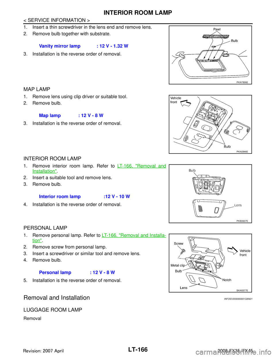
1. Insert a thin screwdriver in the lens end and remove lens.
2. Remove bulb together with substrate.
3. Installation is the reverse order of removal.
MAP LAMP
1. Remove lens using clip driver or suitable tool.
2. Remove bulb.
3. Installation is the reverse order of removal.
INTERIOR ROOM LAMP
1. Remove interior room lamp. Refer to LT-166, "Removal and
Installation".
2. Insert a suitable tool and remove lens.
3. Remove bulb.
4. Installation is the reverse order of removal.
PERSONAL LAMP
1. Remove personal lamp. Refer to LT-166, "Removal and Installa-
tion".
2. Remove screw from personal lamp.
3. Insert a screwdriver or similar tool and remove lens.
4. Remove bulb.
5. Installation is the reverse order of removal.
Removal and InstallationINFOID:0000000001328421
LUGGAGE ROOM LAMP
Removal
Vanity mirror lamp : 12 V - 1.32 W
PKIA7806E
Map lamp : 12 V - 8 W
PKIA2846E
Interior room lamp :12 V - 10 W
PKIB3637E
Personal lamp : 12 V - 8 W
SKIA5577E
3AA93ABC3ACD3AC03ACA3AC03AC63AC53A913A773A893A873A873A8E3A773A983AC73AC93AC03AC3
3A893A873A873A8F3A773A9D3AAF3A8A3A8C3A863A9D3AAF3A8B3A8C