2008 INFINITI FX35 installation
[x] Cancel search: installationPage 3315 of 3924
![INFINITI FX35 2008 Service Manual
LU-30
< SERVICE INFORMATION >[VK45DE]
OIL PUMP
a. Insert oil pump drive spacer according to the directions of crank-
shaft key and the two flat surfaces of oil pump inner rotor.
If the positional INFINITI FX35 2008 Service Manual
LU-30
< SERVICE INFORMATION >[VK45DE]
OIL PUMP
a. Insert oil pump drive spacer according to the directions of crank-
shaft key and the two flat surfaces of oil pump inner rotor.
If the positional](/manual-img/42/57017/w960_57017-3314.png)
LU-30
< SERVICE INFORMATION >[VK45DE]
OIL PUMP
a. Insert oil pump drive spacer according to the directions of crank-
shaft key and the two flat surfaces of oil pump inner rotor.
If the positional relationship does not allow the insertion, rotateoil pump inner rotor with a finger to allow spacer.
b. After confirming that the position of each part is in correct condi- tion to allow for spacer, force fit spacer by lightly tapping with
plastic hammer until it contacts and does not go further.
3. Install in the reverse order of removal after this step.
INSPECTION AFTER INSTALLATION
1. Check the engine oil level. refer to LU-23, "Inspection".
2. Start engine, and check there is no leak of engine oil.
3. Stop engine and wait for 15 minutes.
4. Check the engine oil level and adjust engine oil. Refer to LU-23, "
Inspection".
Disassembly and AssemblyINFOID:0000000001325836
DISASSEMBLY
1. Remove oil pump cover.
2. Remove oil pump inner rotor and oil pump outer rotor from oil pump body.
3. After removing regulator valve plug, remove regulator valve spring and regulator valve.
INSPECTION AFTER DISASSEMBLY
Oil Pump Clearance
Measure the clearance with feeler gauge.
- Clearance between oil pump outer rotor and oil pump body (Posi-
tion 1)
- Tip clearance between oil pump inner rotor and oil pump outer rotor (Position 2)
Measure the clearance with feeler gauge and straightedge.
- Side clearance between oil pump inner rotor and oil pump body (Position 3)
- Side clearance between oil pump outer rotor and oil pump body (Position 4)
Calculate the clearance between oil pump inner rotor and oil pump body as follows:
OIL PUMP INNER ROTOR OUTER DIAMETER
PBIC0058E
Standard : 0.114 - 0.200 mm (0.0045 - 0.0079 in)
Standard : Below 0.180 mm (0.0071 in)
PBIC0139E
Standard : 0.030 - 0.070 mm (0.0012 - 0.0028 in)
Standard : 0.030 - 0.090 mm (0.0012 - 0.0035 in)
PBIC0140E
3AA93ABC3ACD3AC03ACA3AC03AC63AC53A913A773A893A873A873A8E3A773A983AC73AC93AC03AC3
3A893A873A873A8F3A773A9D3AAF3A8A3A8C3A863A9D3AAF3A8B3A8C
Page 3328 of 3924
ENGINE MAINTENANCE (VQ35DE ENGINE)MA-11
< SERVICE INFORMATION >
C
DE
F
G H
I
J
K
M A
B
MA
N
O P
ENGINE MAINTENANCE (VQ35DE ENGINE)
Checking Drive BeltsINFOID:0000000001328900
WARNING:
Be sure to perform when engine is stopped.
1. Inspect belts for cracks, fraying, wear and oil. If necessary, replace.
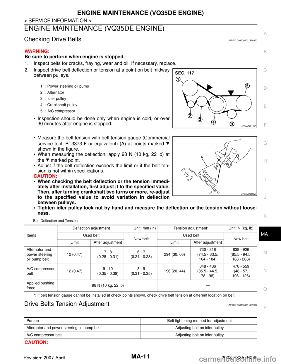
2. Inspect drive belt deflection or tension at a point on belt midway
between pulleys.
Inspection should be done only when engine is cold, or over 30 minutes after engine is stopped.
Measure the belt tension with belt tension gauge (Commercial service tool: BT3373-F or equivalent) (A) at points marked
shown in the figure.
When measuring the deflection, apply 98 N (10 kg, 22 lb) at
the marked point.
Adjust if the belt deflection exceeds the limit or if the belt ten- sion is not within specifications.
CAUTION:
• When checking the belt deflect ion or the tension immedi-
ately after installation, first ad just it to the specified value.
Then, after turning crankshaft two turns or more, re-adjust
to the specified value to avo id variation in deflection
between pulleys.
Tighten idler pulley lock nut by hand and measure the deflection or the tension without loose-
ness.
Belt Deflection and Tension
*: If belt tension gauge cannot be installed at check points shown, check drive belt tension at different location on belt.
Drive Belts Tension AdjustmentINFOID:0000000001328901
CAUTION:
1 : Power steering oil pump
2 : Alternator
3 : Idler pulley
4 : Crankshaft pulley
5 : A/C compressor
JPBIA0421ZZ
JPBIA0422ZZ
Items Deflection adjustment Unit: mm (in) Tension adjustment* Unit: N (kg, lb)
Used belt New beltUsed belt
New belt
Limit After adjustment Limit After adjustment
Alternator and
power steering
oil pump belt 12 (0.47)
7 - 8
(0.28 - 0.31) 6 - 7
(0.24 - 0.28) 294 (30, 66) 730 - 818
(74.5 - 83.5, 164 - 184) 838 - 926
(85.5 - 94.5, 188 - 208)
A/C compressor
belt 12 (0.47)9 - 10
(0.35 - 0.39) 8 - 9
(0.31 - 0.35) 196 (20, 44) 348 - 436
(35.5 - 44.5, 78 - 98) 470 - 559
(48 - 57,
106 - 126)
Applied pushing
force 98 N (10 kg, 22 lb) —
Portion
Belt tightening method for adjustment
Alternator and power steering oil pump belt Adjusting bolt on idler pulley
A/C compressor belt Adjusting bolt on idler pulley
3AA93ABC3ACD3AC03ACA3AC03AC63AC53A913A773A893A873A873A8E3A773A983AC73AC93AC03AC3
3A893A873A873A8F3A773A9D3AAF3A8A3A8C3A863A9D3AAF3A8B3A8C
Page 3329 of 3924
MA-12
< SERVICE INFORMATION >
ENGINE MAINTENANCE (VQ35DE ENGINE)
When belt is replaced with a new one, adjust it to value for “New belt” to accommodate for insuffi-
cient adaptability with pulley grooves.
When deflection or tension of belt being used exceeds “Limit”, adjust it to value for “After adjust-
ment”.
When checking belt deflection or te nsion immediately after installation, first adjust it to the specified
value. Then, after turning crankshaft two turns or mo re, re-adjust to the specified value to avoid vari-
ation in deflection between pulleys.
When installing belt, make sure that it is correctly engaged with pulley grooves.
Keep engine oil, working fluid and engine coolant away from belt and pulley grooves.
Do not twist or bend belt excessively.
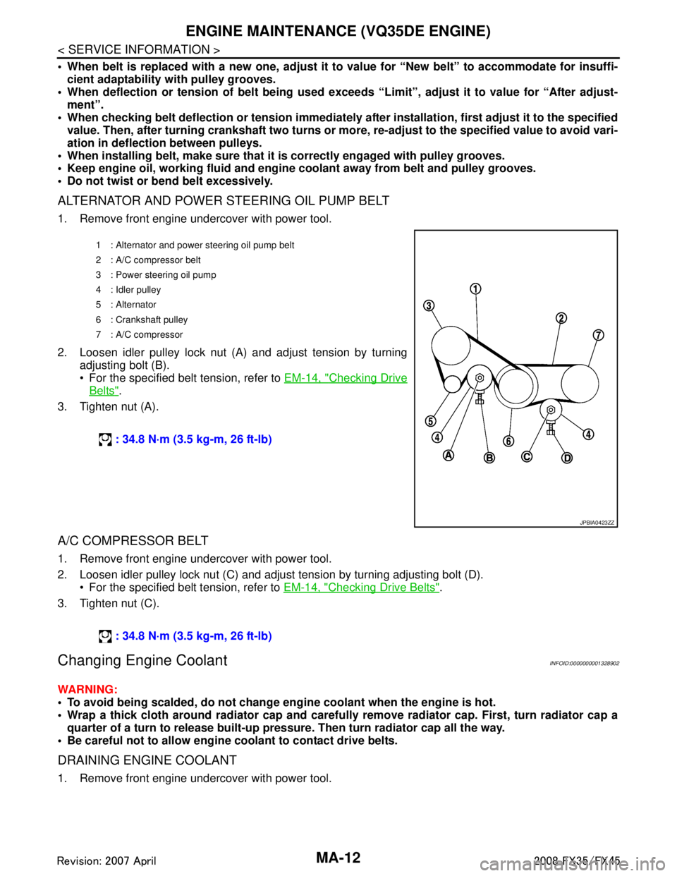
ALTERNATOR AND POWER STEERING OIL PUMP BELT
1. Remove front engine undercover with power tool.
2. Loosen idler pulley lock nut (A) and adjust tension by turning adjusting bolt (B).
For the specified belt tension, refer to EM-14, "
Checking Drive
Belts".
3. Tighten nut (A).
A/C COMPRESSOR BELT
1. Remove front engine undercover with power tool.
2. Loosen idler pulley lock nut (C) and adjust tension by turning adjusting bolt (D). For the specified belt tension, refer to EM-14, "
Checking Drive Belts".
3. Tighten nut (C).
Changing Engine CoolantINFOID:0000000001328902
WARNING:
To avoid being scalded, do not change en gine coolant when the engine is hot.
Wrap a thick cloth around radiator cap and carefully remove radiator cap. First, turn radiator cap a
quarter of a turn to release built-up pressu re. Then turn radiator cap all the way.
Be careful not to allow engine coolant to contact drive belts.
DRAINING ENGINE COOLANT
1. Remove front engine undercover with power tool.
1 : Alternator and power steering oil pump belt
2: A/C compressor belt
3 : Power steering oil pump
4 : Idler pulley
5 : Alternator
6 : Crankshaft pulley
7: A/C compressor
: 34.8 N·m (3.5 kg-m, 26 ft-lb)
JPBIA0423ZZ
: 34.8 N·m (3.5 kg-m, 26 ft-lb)
3AA93ABC3ACD3AC03ACA3AC03AC63AC53A913A773A893A873A873A8E3A773A983AC73AC93AC03AC3
3A893A873A873A8F3A773A9D3AAF3A8A3A8C3A863A9D3AAF3A8B3A8C
Page 3333 of 3924
MA-16
< SERVICE INFORMATION >
ENGINE MAINTENANCE (VQ35DE ENGINE)
Engine oil capacity (Approximate):Unit: (US qt, lmp qt)
CAUTION:
When filling engine oil, do not pull out oil level gauge.
The refill capacity depends on the engine oi l temperature and drain time. Use these specifica-
tions for reference only.
Always use oil level gauge to determine the proper amount of engine oil in engine.
8. Warm up the engine and check area around drain plug and oil filter for engine oil leakage.
9. Stop the engine and wait for 10 minutes.
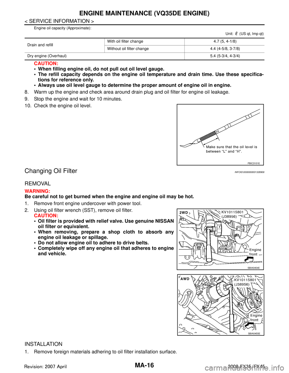
10. Check the engine oil level.
Changing Oil FilterINFOID:0000000001328906
REMOVAL
WARNING:
Be careful not to get burned when the engine and engine oil may be hot.
1. Remove front engine undercover with power tool.
2. Using oil filter wrench (SST), remove oil filter. CAUTION:
Oil filter is provided with relief valve. Use genuine NISSAN
oil filter or equivalent.
When removing, prepare a sh op cloth to absorb any
engine oil leakage or spillage.
Do not allow engine oil to adhere to drive belts.
Completely wipe off any engine oil that adheres to engine and vehicle.
INSTALLATION
1. Remove foreign materials adhering to oil filter installation surface.
Drain and refill With oil filter change 4.7 (5, 4-1/8)
Without oil filter change 4.4 (4-5/8, 3-7/8)
Dry engine (Overhaul) 5.4 (5-3/4, 4-3/4)
PBIC3101E
SBIA0454E
SBIA0455E
3AA93ABC3ACD3AC03ACA3AC03AC63AC53A913A773A893A873A873A8E3A773A983AC73AC93AC03AC3
3A893A873A873A8F3A773A9D3AAF3A8A3A8C3A863A9D3AAF3A8B3A8C
Page 3334 of 3924
ENGINE MAINTENANCE (VQ35DE ENGINE)MA-17
< SERVICE INFORMATION >
C
DE
F
G H
I
J
K
M A
B
MA
N
O P
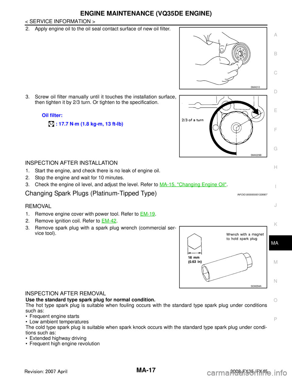
2. Apply engine oil to the oil seal contact surface of new oil filter.
3. Screw oil filter manually until it touches the installation surface,
then tighten it by 2/3 turn. Or tighten to the specification.
INSPECTION AFTER INSTALLATION
1. Start the engine, and check there is no leak of engine oil.
2. Stop the engine and wait for 10 minutes.
3. Check the engine oil level, and adjust the level. Refer to MA-15, "
Changing Engine Oil".
Changing Spark Plugs (Platinum-Tipped Type)INFOID:0000000001328907
REMOVAL
1. Remove engine cover with power tool. Refer to EM-19.
2. Remove ignition coil. Refer to EM-42
.
3. Remove spark plug with a spark plug wrench (commercial ser- vice tool).
INSPECTION AFTER REMOVAL
Use the standard type spark plug for normal condition.
The hot type spark plug is suitable when fouling occurs with the standard type spark plug under conditions
such as:
Frequent engine starts
Low ambient temperatures
The cold type spark plug is suitable when spark knock occurs with the standard type spark plug under condi-
tions such as:
Extended highway driving
Frequent high engine revolution
SMA010
Oil filter:
: 17.7 N·m (1.8 kg-m, 13 ft-lb)
SMA229B
SEM294A
3AA93ABC3ACD3AC03ACA3AC03AC63AC53A913A773A893A873A873A8E3A773A983AC73AC93AC03AC3
3A893A873A873A8F3A773A9D3AAF3A8A3A8C3A863A9D3AAF3A8B3A8C
Page 3335 of 3924
MA-18
< SERVICE INFORMATION >
ENGINE MAINTENANCE (VQ35DE ENGINE)
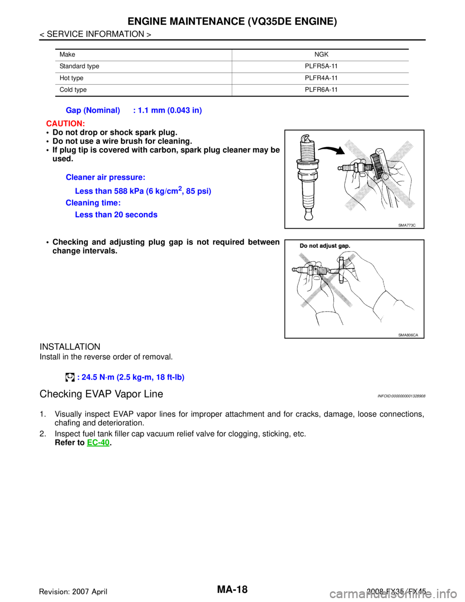
CAUTION:
Do not drop or shock spark plug.
Do not use a wire brush for cleaning.
If plug tip is covered with carbon, spark plug cleaner may be
used.
Checking and adjusting plug gap is not required between
change intervals.
INSTALLATION
Install in the reverse order of removal.
Checking EVAP Vapor LineINFOID:0000000001328908
1. Visually inspect EVAP vapor lines for improper attachment and for cracks, damage, loose connections,
chafing and deterioration.
2. Inspect fuel tank filler cap vacuum relief valve for clogging, sticking, etc.
Refer to EC-40
.
Make NGK
Standard type PLFR5A-11
Hot type PLFR4A-11
Cold type PLFR6A-11
Gap (Nominal) : 1.1 mm (0.043 in)
Cleaner air pressure:
Less than 588 kPa (6 kg/cm
2, 85 psi)
Cleaning time: Less than 20 seconds
SMA773C
SMA806CA
: 24.5 N·m (2.5 kg-m, 18 ft-lb)
3AA93ABC3ACD3AC03ACA3AC03AC63AC53A913A773A893A873A873A8E3A773A983AC73AC93AC03AC3
3A893A873A873A8F3A773A9D3AAF3A8A3A8C3A863A9D3AAF3A8B3A8C
Page 3340 of 3924
ENGINE MAINTENANCE (VK45DE ENGINE)MA-23
< SERVICE INFORMATION >
C
DE
F
G H
I
J
K
M A
B
MA
N
O P
The refill capacity depends on the engine oi l temperature and drain time. Use these specifica-
tions for reference only.
Always use oil level gauge to determine the pr oper amount of engine oil in the engine.
8. Warm up engine and check area around drain plug and oil filter for oil leakage.
9. Stop engine and wait for 15 minutes.
10. Check the engine oil level.
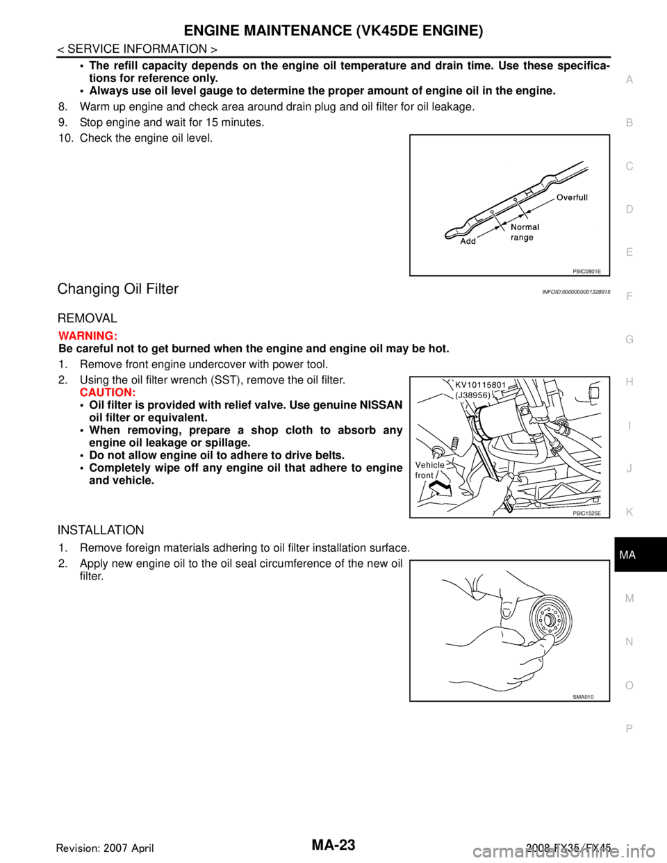
Changing Oil FilterINFOID:0000000001328915
REMOVAL
WARNING:
Be careful not to get burned when th e engine and engine oil may be hot.
1. Remove front engine undercover with power tool.
2. Using the oil filter wrench (SST), remove the oil filter. CAUTION:
Oil filter is provided with relief valve. Use genuine NISSAN
oil filter or equivalent.
When removing, prepare a s hop cloth to absorb any
engine oil leakage or spillage.
Do not allow engine oil to adhere to drive belts.
Completely wipe off any engine oil that adhere to engine
and vehicle.
INSTALLATION
1. Remove foreign materials adhering to oil filter installation surface.
2. Apply new engine oil to the oil seal circumference of the new oil filter.
PBIC0801E
PBIC1525E
SMA010
3AA93ABC3ACD3AC03ACA3AC03AC63AC53A913A773A893A873A873A8E3A773A983AC73AC93AC03AC3
3A893A873A873A8F3A773A9D3AAF3A8A3A8C3A863A9D3AAF3A8B3A8C
Page 3341 of 3924
MA-24
< SERVICE INFORMATION >
ENGINE MAINTENANCE (VK45DE ENGINE)
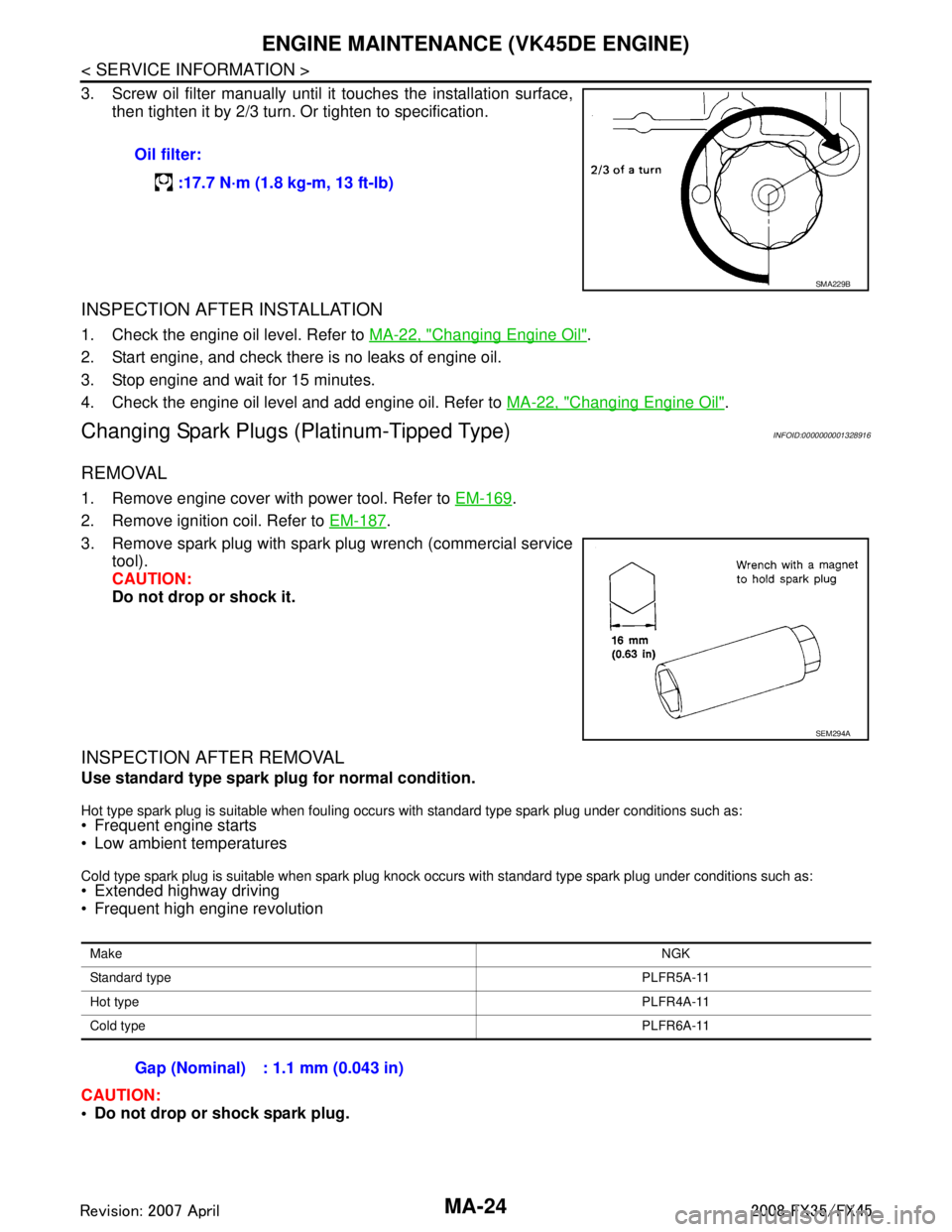
3. Screw oil filter manually until it touches the installation surface,
then tighten it by 2/3 turn. Or tighten to specification.
INSPECTION AFTER INSTALLATION
1. Check the engine oil level. Refer to MA-22, "Changing Engine Oil".
2. Start engine, and check there is no leaks of engine oil.
3. Stop engine and wait for 15 minutes.
4. Check the engine oil level and add engine oil. Refer to MA-22, "
Changing Engine Oil".
Changing Spark Plugs (Platinum-Tipped Type)INFOID:0000000001328916
REMOVAL
1. Remove engine cover with power tool. Refer to EM-169.
2. Remove ignition coil. Refer to EM-187
.
3. Remove spark plug with spark plug wrench (commercial service tool).
CAUTION:
Do not drop or shock it.
INSPECTION AFTER REMOVAL
Use standard type spark plug for normal condition.
Hot type spark plug is suitable when fouling occurs with standard type spark plug under conditions such as: Frequent engine starts
Low ambient temperatures
Cold type spark plug is suitable when spark plug knock occurs with standard type spark plug under conditions such as: Extended highway driving
Frequent high engine revolution
CAUTION:
Do not drop or shock spark plug.Oil filter:
:17.7 N·m (1.8 kg-m, 13 ft-lb)
SMA229B
SEM294A
Make NGK
Standard type PLFR5A-11
Hot type PLFR4A-11
Cold type PLFR6A-11
Gap (Nominal) : 1.1 mm (0.043 in)
3AA93ABC3ACD3AC03ACA3AC03AC63AC53A913A773A893A873A873A8E3A773A983AC73AC93AC03AC3
3A893A873A873A8F3A773A9D3AAF3A8A3A8C3A863A9D3AAF3A8B3A8C