Page 3388 of 3924
PG-24
< SERVICE INFORMATION >
IPDM E/R (INTELLIGENT POWER DISTRIBUTION MODULE ENGINE ROOM)
OK or NG
OK >> GO TO 2.
NG >> If fuse or fusible link blown, be sure to e liminate cause of malfunction before installing new one.
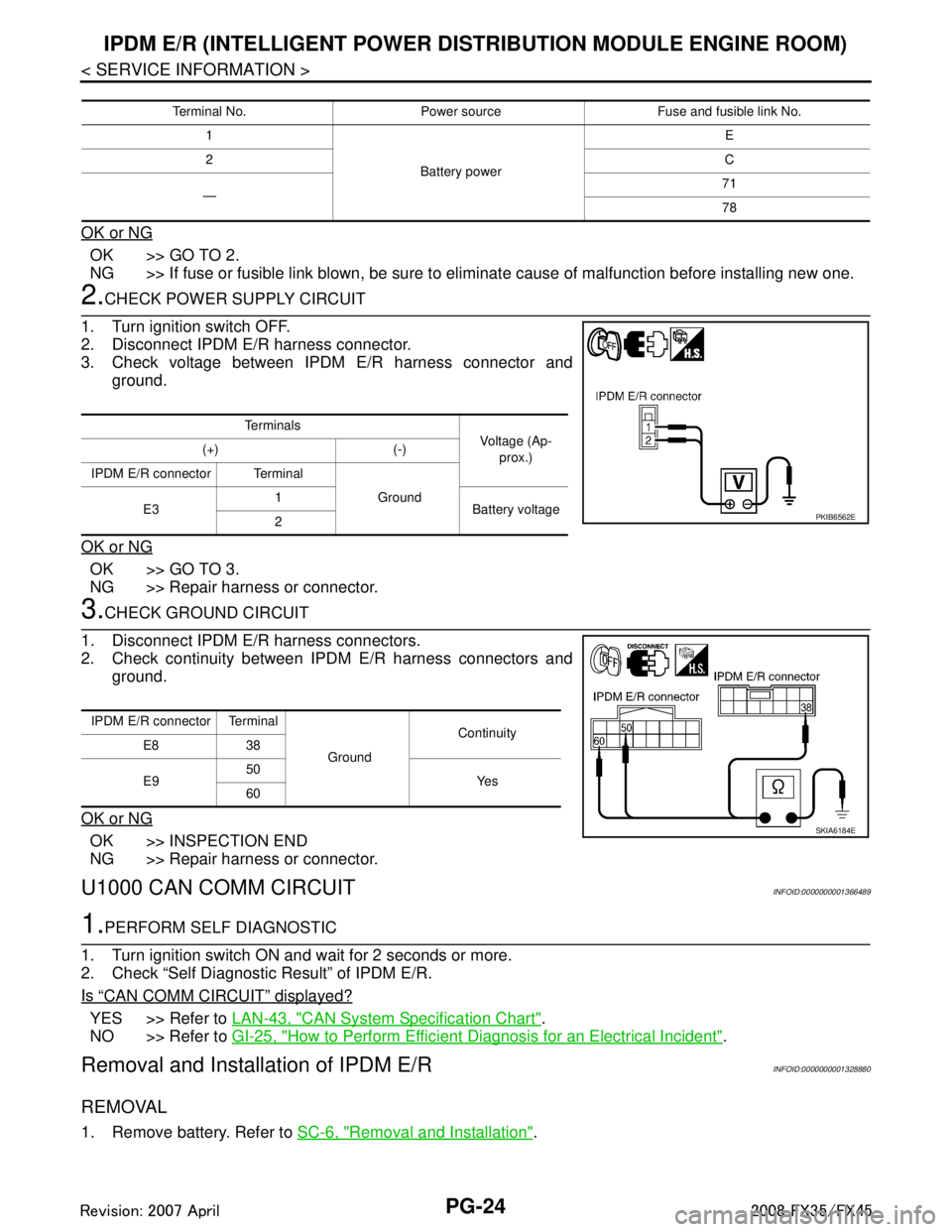
2.CHECK POWER SUPPLY CIRCUIT
1. Turn ignition switch OFF.
2. Disconnect IPDM E/R harness connector.
3. Check voltage between IPDM E/R harness connector and ground.
OK or NG
OK >> GO TO 3.
NG >> Repair harness or connector.
3.CHECK GROUND CIRCUIT
1. Disconnect IPDM E/R harness connectors.
2. Check continuity between IPDM E/R harness connectors and ground.
OK or NG
OK >> INSPECTION END
NG >> Repair harness or connector.
U1000 CAN COMM CIRCUITINFOID:0000000001366489
1.PERFORM SELF DIAGNOSTIC
1. Turn ignition switch ON and wait for 2 seconds or more.
2. Check “Self Diagnostic Result” of IPDM E/R.
Is
“CAN COMM CIRCUIT” displayed?
YES >> Refer to LAN-43, "CAN System Specification Chart".
NO >> Refer to GI-25, "
How to Perform Efficient Diagnosis for an Electrical Incident".
Removal and Installation of IPDM E/RINFOID:0000000001328880
REMOVAL
1. Remove battery. Refer to SC-6, "Removal and Installation".
Terminal No. Power source Fuse and fusible link No.
1
Battery power E
2 C
— 71
78
Te r m i n a l s
Voltage (Ap-
prox.)
(+) (-)
IPDM E/R connector Terminal Ground
E3 1
Battery voltage
2
PKIB6562E
IPDM E/R connector Terminal
GroundContinuity
E8 38
E9 50
Ye s
60
SKIA6184E
3AA93ABC3ACD3AC03ACA3AC03AC63AC53A913A773A893A873A873A8E3A773A983AC73AC93AC03AC3
3A893A873A873A8F3A773A9D3AAF3A8A3A8C3A863A9D3AAF3A8B3A8C
Page 3389 of 3924
IPDM E/R (INTELLIGENT POWER DISTRIBUTION MODULE ENGINE ROOM)
PG-25
< SERVICE INFORMATION >
C
D E
F
G H
I
J
L
M A
B
PG
N
O P
2. Remove IPDM E/R cover A. While pressing pawl on backside of IPDM E/R cover B toward vehicle front to unlock, lift up IPDM E/
R.
3. While pressing pawls on right and left side of IPDM E/R, remove IPDM E/R cover B from IPDM E/R.
4. Remove harness connector from IPDM E/R.
INSTALLATION
Installation is the reverse order of removal.
SKIA4968E
SKIA1902E
SKIA4969E
3AA93ABC3ACD3AC03ACA3AC03AC63AC53A913A773A893A873A873A8E3A773A983AC73AC93AC03AC3
3A893A873A873A8F3A773A9D3AAF3A8A3A8C3A863A9D3AAF3A8B3A8C
Page 3443 of 3924
PR-1
DRIVELINE/AXLE
CEF
G H
I
J
K L
M
SECTION PR
A
B
PR
N
O P
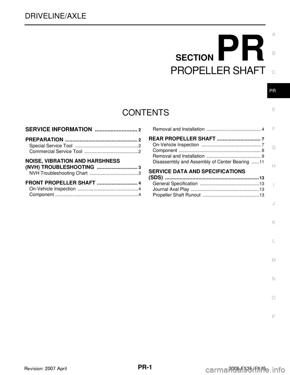
CONTENTS
PROPELLER SHAFT
SERVICE INFORMATION .. ..........................2
PREPARATION .............................................. .....2
Special Service Tool ........................................... ......2
Commercial Service Tool ..........................................2
NOISE, VIBRATION AND HARSHNESS
(NVH) TROUBLESHOOTING .............................
3
NVH Troubleshooting Chart ................................ ......3
FRONT PROPELLER SHAFT .............................4
On-Vehicle Inspection ......................................... ......4
Component ................................................................4
Removal and Installation ..................................... .....4
REAR PROPELLER SHAFT ..............................7
On-Vehicle Inspection ..............................................7
Component ...............................................................8
Removal and Installation ..........................................9
Disassembly and Assembly of Center Bearing .......11
SERVICE DATA AND SPECIFICATIONS
(SDS) .................................................................
13
General Specification ..............................................13
Journal Axal Play .....................................................13
Propeller Shaft Runout ............................................13
3AA93ABC3ACD3AC03ACA3AC03AC63AC53A913A773A893A873A873A8E3A773A983AC73AC93AC03AC3
3A893A873A873A8F3A773A9D3AAF3A8A3A8C3A863A9D3AAF3A8B3A8C
Page 3445 of 3924
NOISE, VIBRATION AND HARSHNESS (NVH) TROUBLESHOOTINGPR-3
< SERVICE INFORMATION >
CEF
G H
I
J
K L
M A
B
PR
N
O P
NOISE, VIBRATION AND HARSHN ESS (NVH) TROUBLESHOOTING
NVH Troubleshooting ChartINFOID:0000000001327465
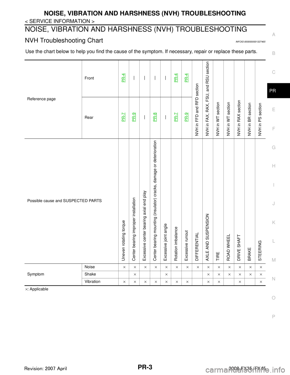
Use the chart below to help you find t he cause of the symptom. If necessary, repair or replace these parts.
×: Applicable
Reference page
Front
PR-4—
—
—
—
PR-4PR-4
NVH in FFD an d RFD section
NVH in FAX, RAX, FS U, and RSU section
NVH in WT section
NVH in WT section
NVH in RAX section
NVH in BR section
NVH in PS section
RearPR-7PR-9—
PR-8—
PR-7PR-9
Possible cause and SUSPECTED PARTS
Uneven rotating torque
Center bearing improper installation
Excessive center bearing axial end play
Center bearing mounting (insulator) cracks, damage or deterioration
Excessive joint angle
Rotation imbalance
Excessive runout
DIFFERENTIAL
AXLE AND SUSPENSION
TIRE
ROAD WHEEL
DRIVE SHAFT
BRAKE
STEERING
Symptom Noise
××××××××××××××
Shake × × ××××××
Vibration ××××××× ×× × ×
3AA93ABC3ACD3AC03ACA3AC03AC63AC53A913A773A893A873A873A8E3A773A983AC73AC93AC03AC3
3A893A873A873A8F3A773A9D3AAF3A8A3A8C3A863A9D3AAF3A8B3A8C
Page 3446 of 3924
PR-4
< SERVICE INFORMATION >
FRONT PROPELLER SHAFT
FRONT PROPELLER SHAFT
On-Vehicle InspectionINFOID:0000000001327466
APPEARANCE AND NOISE INSPECTION
Check the propeller shaft tube surface for dents or cracks. If damaged, replace propeller shaft assembly.
PROPELLER SHAFT VIBRATION
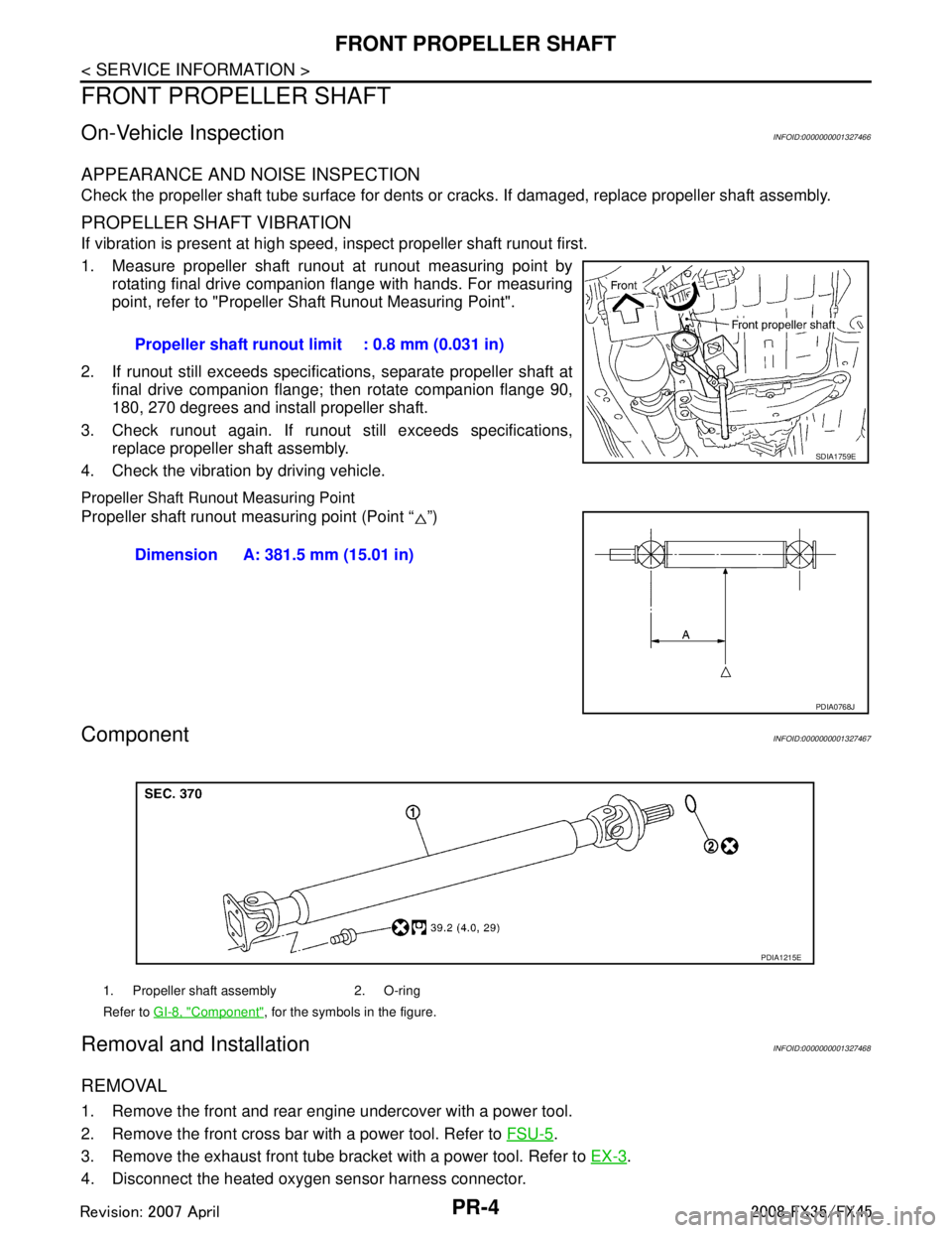
If vibration is present at high speed, inspect propeller shaft runout first.
1. Measure propeller shaft runout at runout measuring point by rotating final drive companion flange with hands. For measuring
point, refer to "Propeller Shaft Runout Measuring Point".
2. If runout still exceeds specifications, separate propeller shaft at final drive companion flange; then rotate companion flange 90,
180, 270 degrees and install propeller shaft.
3. Check runout again. If runout still exceeds specifications, replace propeller shaft assembly.
4. Check the vibration by driving vehicle.
Propeller Shaft Runout Measuring Point
Propeller shaft runout measuring point (Point “ ”)
ComponentINFOID:0000000001327467
Removal and InstallationINFOID:0000000001327468
REMOVAL
1. Remove the front and rear engine undercover with a power tool.
2. Remove the front cross bar with a power tool. Refer to FSU-5
.
3. Remove the exhaust front tube bracket with a power tool. Refer to EX-3
.
4. Disconnect the heated oxygen sensor harness connector. Propeller shaft runout limit : 0.8 mm (0.031 in)
SDIA1759E
Dimension A: 381.5 mm (15.01 in)
PDIA0768J
1. Propeller shaft assembly 2. O-ring
Refer to
GI-8, "
Component", for the symbols in the figure.
PDIA1215E
3AA93ABC3ACD3AC03ACA3AC03AC63AC53A913A773A893A873A873A8E3A773A983AC73AC93AC03AC3
3A893A873A873A8F3A773A9D3AAF3A8A3A8C3A863A9D3AAF3A8B3A8C
Page 3447 of 3924
FRONT PROPELLER SHAFTPR-5
< SERVICE INFORMATION >
CEF
G H
I
J
K L
M A
B
PR
N
O P
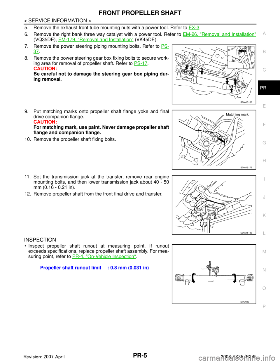
5. Remove the exhaust front tube mounting nuts with a power tool. Refer to EX-3.
6. Remove the right bank three way catalyst with a power tool. Refer to EM-26, "
Removal and Installation"
(VQ35DE), EM-179, "Removal and Installation" (VK45DE).
7. Remove the power steering piping mounting bolts. Refer to PS-
37.
8. Remove the power steering gear box fixing bolts to secure work- ing area for removal of propeller shaft. Refer to PS-17
.
CAUTION:
Be careful not to damage the steering gear box piping dur-
ing removal.
9. Put matching marks onto propeller shaft flange yoke and final drive companion flange.
CAUTION:
For matching mark, use paint. Never damage propeller shaft
flange and companion flange.
10. Remove the propeller shaft fixing bolts.
11. Set the transmission jack at the transfer, remove rear engine mounting bolts, and then lower transmission jack about 40 - 50
mm (0.16 - 0.21 in).
12. Remove propeller shaft from the front final drive and transfer.
INSPECTION
Inspect propeller shaft runout at measuring point. If runout exceeds specifications, replace propeller shaft assembly. For mea-
suring point, refer to PR-4, "
On-Vehicle Inspection".
SDIA1516E
SDIA1517E
SDIA1518E
Propeller shaft runout limit : 0.8 mm (0.031 in)
SPD106
3AA93ABC3ACD3AC03ACA3AC03AC63AC53A913A773A893A873A873A8E3A773A983AC73AC93AC03AC3
3A893A873A873A8F3A773A9D3AAF3A8A3A8C3A863A9D3AAF3A8B3A8C
Page 3448 of 3924
PR-6
< SERVICE INFORMATION >
FRONT PROPELLER SHAFT
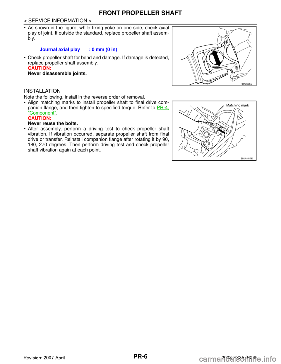
As shown in the figure, while fixing yoke on one side, check axialplay of joint. If outside the standard, replace propeller shaft assem-
bly.
Check propeller shaft for bend and damage. If damage is detected, replace propeller shaft assembly.
CAUTION:
Never disassemble joints.
INSTALLATION
Note the following, install in the reverse order of removal.
Align matching marks to install propeller shaft to final drive com-panion flange, and then tighten to specified torque. Refer to PR-4,
"Component".
CAUTION:
Never reuse the bolts.
After assembly, perform a driving test to check propeller shaft vibration. If vibration occurred, separate propeller shaft from final
drive or transfer. Reinstall companion flange after rotating it by 90,
180, 270 degrees. Then perform driving test and check propeller
shaft vibration again at each point. Journal axial play : 0 mm (0 in)
PDA0005D
SDIA1517E
3AA93ABC3ACD3AC03ACA3AC03AC63AC53A913A773A893A873A873A8E3A773A983AC73AC93AC03AC3
3A893A873A873A8F3A773A9D3AAF3A8A3A8C3A863A9D3AAF3A8B3A8C
Page 3451 of 3924
REAR PROPELLER SHAFTPR-9
< SERVICE INFORMATION >
CEF
G H
I
J
K L
M A
B
PR
N
O P
Removal and InstallationINFOID:0000000001327471
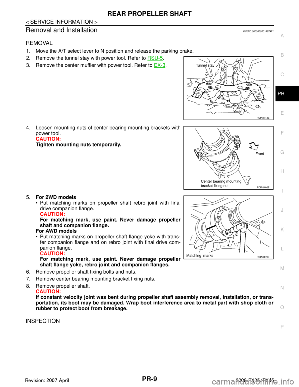
REMOVAL
1. Move the A/T select lever to N position and release the parking brake.
2. Remove the tunnel stay with power tool. Refer to RSU-5
.
3. Remove the center muffler with power tool. Refer to EX-3
.
4. Loosen mounting nuts of center bearing mounting brackets with power tool.
CAUTION:
Tighten mounting nuts temporarily.
5. For 2WD models
Put matching marks on propeller shaft rebro joint with final
drive companion flange.
CAUTION:
For matching mark, use paint. Never damage propeller
shaft and companion flange.
For AWD models
Put matching marks on propeller shaft flange yoke with trans- fer companion flange and on rebro joint with final drive com-
panion flange.
CAUTION:
For matching mark, use paint. Never damage propeller
shaft flange yoke, rebro jo int and companion flanges.
6. Remove propeller shaft fixing bolts and nuts.
7. Remove center bearing mounting bracket fixing nuts.
8. Remove propeller shaft. CAUTION:
If constant velocity joint was bent during prop eller shaft assembly removal, installation, or trans-
portation, its boot may be damaged. Wrap boot interference area to metal part with shop cloth or
rubber to protect boot from breakage.
INSPECTION
PDIA0744E
PDIA0402E
PDIA0470E
3AA93ABC3ACD3AC03ACA3AC03AC63AC53A913A773A893A873A873A8E3A773A983AC73AC93AC03AC3
3A893A873A873A8F3A773A9D3AAF3A8A3A8C3A863A9D3AAF3A8B3A8C