2008 INFINITI FX35 installation
[x] Cancel search: installationPage 3342 of 3924
ENGINE MAINTENANCE (VK45DE ENGINE)MA-25
< SERVICE INFORMATION >
C
DE
F
G H
I
J
K
M A
B
MA
N
O P
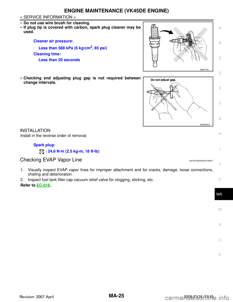
Do not use wire brush for cleaning.
If plug tip is covered with car bon, spark plug cleaner may be
used.
Checking and adjusting plug gap is not required between
change intervals.
INSTALLATION
Install in the reverse order of removal.
Checking EVAP Vapor LineINFOID:0000000001328917
1. Visually inspect EVAP vapor lines for improper attachment and for cracks, damage, loose connections,
chafing and deterioration.
2. Inspect fuel tank filler cap vacuum relief valve for clogging, sticking, etc.
Refer to EC-618
.
Cleaner air pressure:
Less than 588 kPa (6 kg/cm
2, 85 psi)
Cleaning time: Less than 20 seconds
SMA773C
SMA806CA
Spark plug:
: 24.6 N·m (2.5 kg-m, 18 ft-lb)
3AA93ABC3ACD3AC03ACA3AC03AC63AC53A913A773A893A873A873A8E3A773A983AC73AC93AC03AC3
3A893A873A873A8F3A773A9D3AAF3A8A3A8C3A863A9D3AAF3A8B3A8C
Page 3348 of 3924
CHASSIS AND BODY MAINTENANCEMA-31
< SERVICE INFORMATION >
C
DE
F
G H
I
J
K
M A
B
MA
N
O P
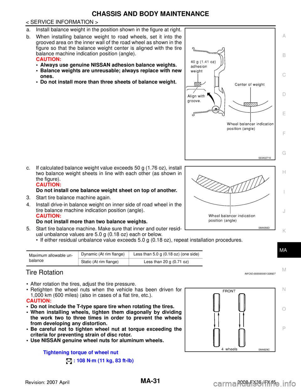
a. Install balance weight in the position shown in the figure at right.
b. When installing balance weight to road wheels, set it into the grooved area on the inner wall of the road wheel as shown in the
figure so that the balance weight center is aligned with the tire
balance machine indication position (angle).
CAUTION:
Always use genuine NISSAN adhesion balance weights.
Balance weights are unreusable; always replace with newones.
Do not install more than three sheets of balance weight.
c. If calculated balance weight value exceeds 50 g (1.76 oz), install two balance weight sheets in line with each other (as shown in
the figure).
CAUTION:
Do not install one balance weig ht sheet on top of another.
3. Start tire balance machine again.
4. Install drive-in balance weight on inner side of road wheel in the tire balance machine indication position (angle).
CAUTION:
Do not install more than two balance weights.
5. Start tire balance machine. Make sure that inner and outer resid- ual unbalance values are 5.0 g (0.18 oz) each or below.
If either residual unbalance value exceeds 5.0 g (0.18 oz), repeat installation procedures.
Tire RotationINFOID:0000000001328927
After rotation the tires, adjust the tire pressure.
Retighten the wheel nuts when the vehicle has been driven for
1,000 km (600 miles) (also in cases of a flat tire, etc.).
CAUTION:
Do not include the T-type spare tire when rotating the tires.
When installing wheels, tighte n them diagonally by dividing
the work two to three times in order to prevent the wheels
from developing any distortion.
Be careful not to tighten wh eel nut at torque exceeding the
criteria for preventing strain of disc rotor.
Use NISSAN genuine wheel nu ts for aluminum wheels.
SEIA0271E
Maximum allowable un-
balanceDynamic (At rim flange) Less than 5.0 g (0.18 oz) (one side)
Static (At rim flange) Less than 20 g (0.71 oz)
SMA056D
Tightening torque of wheel nut
: 108 N·m (11 kg, 83 ft-lb)SMA829C
3AA93ABC3ACD3AC03ACA3AC03AC63AC53A913A773A893A873A873A8E3A773A983AC73AC93AC03AC3
3A893A873A873A8F3A773A9D3AAF3A8A3A8C3A863A9D3AAF3A8B3A8C
Page 3356 of 3924

PB-1
BRAKES
C
DE
G H
I
J
K L
M
SECTION PB
A
B
PB
N
O P
CONTENTS
PARKING BRAKE SYSTEM
SERVICE INFORMATION .. ..........................2
PREPARATION .............................................. .....2
Commercial Service Tool .................................... ......2
PARKING BRAKE SYSTEM ...............................3
On-Vehicle Inspection ......................................... ......3
PARKING BRAKE CONTROL ............................4
Component .......................................................... ......4
Removal and Installation ..................................... .....4
PARKING BRAKE SHOE ..................................6
Component ...............................................................6
Removal and Installation ..........................................6
SERVICE DATA AND SPECIFICATIONS
(SDS) ..................................................................
9
Parking Drum Brake .................................................9
Parking Brake Control ..............................................9
3AA93ABC3ACD3AC03ACA3AC03AC63AC53A913A773A893A873A873A8E3A773A983AC73AC93AC03AC3
3A893A873A873A8F3A773A9D3AAF3A8A3A8C3A863A9D3AAF3A8B3A8C
Page 3359 of 3924

PB-4
< SERVICE INFORMATION >
PARKING BRAKE CONTROL
PARKING BRAKE CONTROL
ComponentINFOID:0000000001327647
Removal and InstallationINFOID:0000000001327648
REMOVAL
1. Remove front kicking plate (driver side). Refer to IP-11, "Removal and Installation".
2. Remove front body side welt (driver side). Refer to EI-38
.
3. Remove dash side finisher (driver side). Refer to IP-10
.
4. Remove instrument lower panel (driver side). Refer to IP-10
.
5. Remove adjusting nut.
6. Remove front cable installation bolts, nuts, and lock plate, then remove front cable from the vehicle.
7. Remove heat insulator between center muffler and rear propeller shaft.
8. Remove exhaust center muffler. Refer to EX-3
.
9. Remove propeller shaft. Refer to PR-9, "
Removal and Installation".
10. Remove rear disc caliper and disc rotors. Refer to BR-25, "
Removal and Installation of Brake Caliper
Assembly".
11. Remove parking brake shoe, and remove r ear cable from toggle lever. Refer to PB-6
.
1. Device assembly 2. Spring insulator 3. Return spring
4. Lock plate 5. Front cable 6. Return spring
7. Rear left cable 8. Rear right cable 9. Pin
10. Adjusting nut
SFIA1943E
3AA93ABC3ACD3AC03ACA3AC03AC63AC53A913A773A893A873A873A8E3A773A983AC73AC93AC03AC3
3A893A873A873A8F3A773A9D3AAF3A8A3A8C3A863A9D3AAF3A8B3A8C
Page 3360 of 3924
PARKING BRAKE CONTROLPB-5
< SERVICE INFORMATION >
C
DE
G H
I
J
K L
M A
B
PB
N
O P
12. Remove right and left rear cables installation nuts, bolts, and remove right and left rear cable assembly from the vehicle.
INSTALLATION
1. Install in the reverse order of removal. Tighten the mounting bolts and nuts to the specified torque. Referto PB-4, "
Component".
CAUTION:
Do not reuse adjusting nut after removing it.
2. Adjust parking brake. Refer to PB-3, "
On-Vehicle Inspection".
3AA93ABC3ACD3AC03ACA3AC03AC63AC53A913A773A893A873A873A8E3A773A983AC73AC93AC03AC3
3A893A873A873A8F3A773A9D3AAF3A8A3A8C3A863A9D3AAF3A8B3A8C
Page 3361 of 3924
PB-6
< SERVICE INFORMATION >
PARKING BRAKE SHOE
PARKING BRAKE SHOE
ComponentINFOID:0000000001327649
Removal and InstallationINFOID:0000000001327650
REMOVAL
WARNING:
Clean brakes with a vacuum dust collector to minimize the hazard of air borne particles or other mate-
rials.
CAUTION:
• Remove wheel, and remove disc rotor with parki ng brake pedal completely released. Refer to BR-25,
"Removal and Installation of Brake Caliper Assembly".
When removing disc rotor, mark both disc rotor and wheel hub for alignment.
1. Remove rear tires from vehicle with a power tool.
2. Remove disc rotor with the parking brake pedal in the completely released position.
3. Remove disc rotor. If disc rotor cannot be removed, remove as follows:
a. Secure the disc rotor in place with wheel nuts and remove adjuster hole plug.
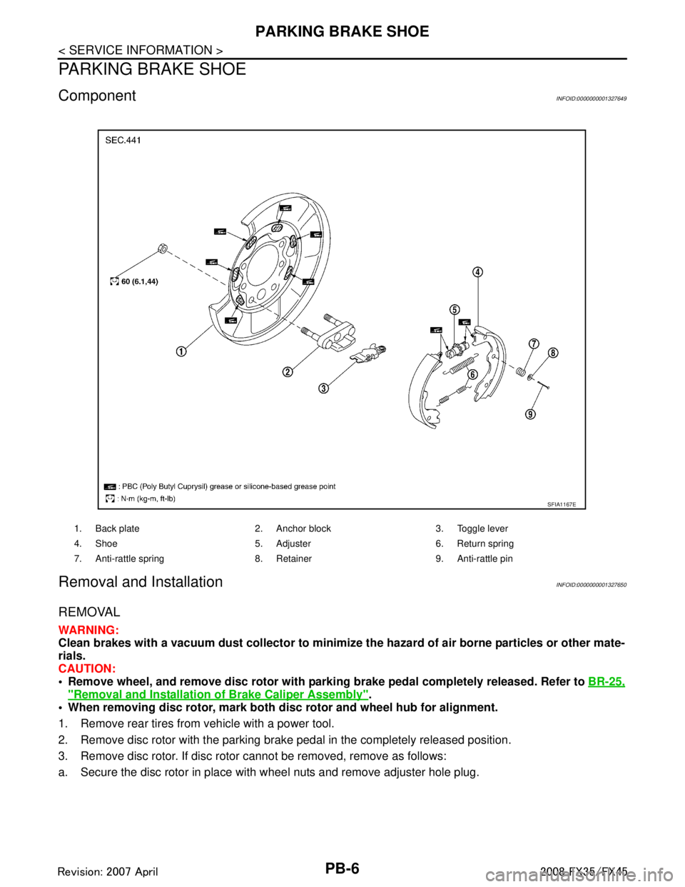
1. Back plate 2. Anchor block 3. Toggle lever
4. Shoe 5. Adjuster 6. Return spring
7. Anti-rattle spring 8. Retainer 9. Anti-rattle pin
SFIA1167E
3AA93ABC3ACD3AC03ACA3AC03AC63AC53A913A773A893A873A873A8E3A773A983AC73AC93AC03AC3
3A893A873A873A8F3A773A9D3AAF3A8A3A8C3A863A9D3AAF3A8B3A8C
Page 3362 of 3924
PARKING BRAKE SHOEPB-7
< SERVICE INFORMATION >
C
DE
G H
I
J
K L
M A
B
PB
N
O P
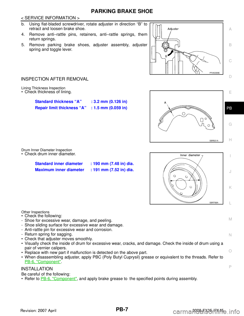
b. Using flat-bladed screwdriver, rotate adjuster in direction “B” to retract and loosen brake shoe.
4. Remove anti −rattle pins, retainers, anti −rattle springs, them
return springs.
5. Remove parking brake shoes, adjuster assembly, adjuster spring and toggle lever.
INSPECTION AFTER REMOVAL
Lining Thickness Inspection
Check thickness of lining.
Drum Inner Diameter Inspection
Check drum inner diameter.
Other Inspections
Check the following:
- Shoe for excessive wear, damage, and peeling.
- Shoe sliding surface for excessive wear and damage.
- Anti-rattle pin for excessive wear and corrosion.
- Return spring for sagging.
Check that adjuster moves smoothly.
Visually check the inside of drum for excessive wear , cracks, and damage. Check the inside of drum using a
pair of vernier calipers.
Replace with new part if malfunction is detected on the above part.
When disassembling adjuster, apply PBC (Poly Butyl Cupr ysil) grease or equivalent to the threads. Refer to
PB-6, "
Component".
INSTALLATION
Be careful of the following:
Refer to PB-6, "
Component", and apply brake grease to the specified points during assembly.
PFIA0309E
Standard thickness “A” : 3.2 mm (0.126 in)
Repair limit thickness “A” : 1.5 mm (0.059 in)
SBR021A
Standard inner diameter : 190 mm (7.48 in) dia.
Maximum inner diameter : 191 mm (7.52 in) dia.
SBR768A
3AA93ABC3ACD3AC03ACA3AC03AC63AC53A913A773A893A873A873A8E3A773A983AC73AC93AC03AC3
3A893A873A873A8F3A773A9D3AAF3A8A3A8C3A863A9D3AAF3A8B3A8C
Page 3365 of 3924

PG-1
ELECTRICAL
C
DE
F
G H
I
J
L
M
SECTION PG
A
B
PG
N
O P
CONTENTS
POWER SUPPLY, GROUND & CIRCUIT ELEMENTS
SERVICE INFORMATION .. ..........................2
DTC INDEX ..................................................... .....2
U1000 .................................................................. ......2
POWER SUPPLY ROUTING CIRCUIT ...............3
Schematic ........................................................... ......3
Wiring Diagram - POWER - ......................................4
Fuse ........................................................................16
Fusible Link .............................................................16
Circuit Breaker ........................................................16
IPDM E/R (INTELLIGENT POWER DISTRI-
BUTION MODULE ENGINE ROOM) .................
17
System Description ............................................. ....17
CAN Communication System Description ...............18
CAN Communication Unit .......................................18
Function of Detecting Ignition Relay Malfunction ....18
CONSULT-III Function (IPDM E/R) ..................... ....18
Auto Active Test ......................................................20
Schematic ...............................................................22
IPDM E/R Terminal Arrangement ...........................23
IPDM E/R Power/Ground Circuit Inspection ...........23
U1000 CAN COMM CIRCUIT .................................24
Removal and Installation of IPDM E/R ....................24
GROUND ...........................................................26
Ground Distribution .............................................. ....26
HARNESS .........................................................40
Harness Layout ................................................... ....40
Wiring Diagram Codes (Cell Codes) .......................60
ELECTRICAL UNITS LOCATION ....................64
Electrical Units Location ..........................................64
HARNESS CONNECTOR .................................68
Description ...............................................................68
ELECTRICAL UNITS ........................................71
Terminal Arrangement .............................................71
SMJ (SUPER MULTIPLE JUNCTION) .............73
Terminal Arrangement .............................................73
STANDARDIZED RELAY .................................75
Description ...............................................................75
FUSE BLOCK - JUNCTION BOX (J/B) ............77
Terminal Arrangement .............................................77
FUSE, FUSIBLE LINK AND RELAY BOX ........78
Terminal Arrangement .............................................78
3AA93ABC3ACD3AC03ACA3AC03AC63AC53A913A773A893A873A873A8E3A773A983AC73AC93AC03AC3
3A893A873A873A8F3A773A9D3AAF3A8A3A8C3A863A9D3AAF3A8B3A8C