Page 2963 of 3924
GW-50
< SERVICE INFORMATION >
FRONT DOOR GLASS AND REGULATOR
FRONT DOOR GLASS AND REGULATOR
Removal and InstallationINFOID:0000000001327990
DOOR GLASS
Removal
1. Remove the front door finisher. Refer to EI-36.
2. Remove speaker unit. Refer to AV-43, "
Removal and Installation for Front Door Speaker".
3. Operate the power window main switch to raise or lower the door window until the glass mounting bolts can be seen.
4. Remove the glass mounting bolts.
5. Remove the module stop bolts.
1. Door glass 2. Regulator assembly 3. Power window motor
4. Module assembly 5. Bolt 6. Hole cover
PIIA4728E
PIIA4729E
3AA93ABC3ACD3AC03ACA3AC03AC63AC53A913A773A893A873A873A8E3A773A983AC73AC93AC03AC3
3A893A873A873A8F3A773A9D3AAF3A8A3A8C3A863A9D3AAF3A8B3A8C
Page 2964 of 3924
FRONT DOOR GLASS AND REGULATORGW-51
< SERVICE INFORMATION >
C
DE
F
G H
J
K L
M A
B
GW
N
O P
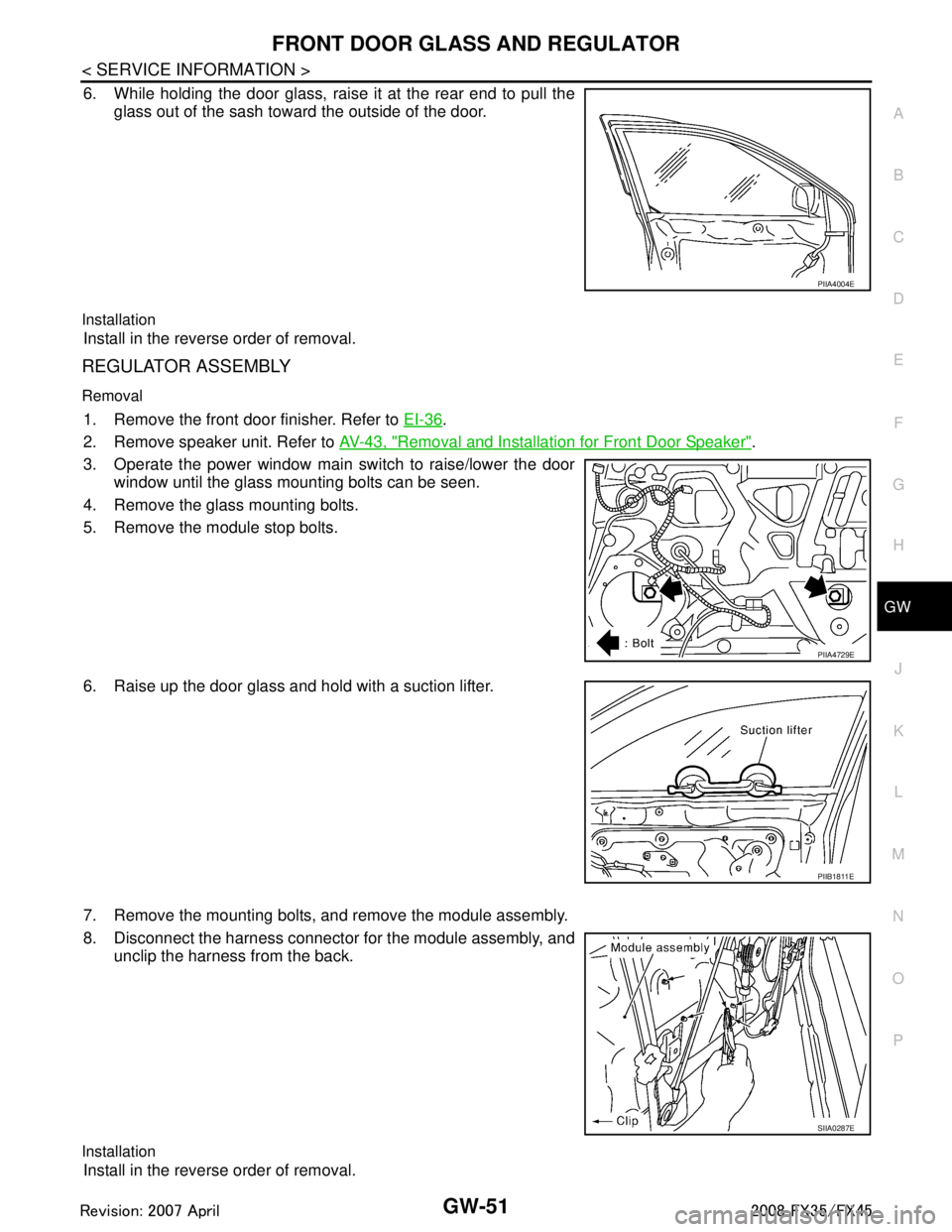
6. While holding the door glass, raise it at the rear end to pull the glass out of the sash toward the outside of the door.
Installation
Install in the reverse order of removal.
REGULATOR ASSEMBLY
Removal
1. Remove the front door finisher. Refer to EI-36.
2. Remove speaker unit. Refer to AV-43, "
Removal and Installation for Front Door Speaker".
3. Operate the power window main switch to raise/lower the door window until the glass mounting bolts can be seen.
4. Remove the glass mounting bolts.
5. Remove the module stop bolts.
6. Raise up the door glass and hold with a suction lifter.
7. Remove the mounting bolts, and remove the module assembly.
8. Disconnect the harness connector for the module assembly, and
unclip the harness from the back.
Installation
Install in the reverse order of removal.
PIIA4004E
PIIA4729E
PIIB1811E
SIIA0287E
3AA93ABC3ACD3AC03ACA3AC03AC63AC53A913A773A893A873A873A8E3A773A983AC73AC93AC03AC3
3A893A873A873A8F3A773A9D3AAF3A8A3A8C3A863A9D3AAF3A8B3A8C
Page 2965 of 3924
GW-52
< SERVICE INFORMATION >
FRONT DOOR GLASS AND REGULATOR
Inspection after Removal
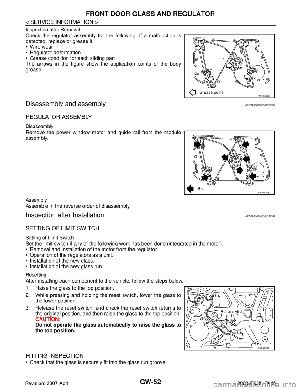
Check the regulator assembly for the following. If a malfunction is
detected, replace or grease it.
Wire wear
Regulator deformation
Grease condition for each sliding part
The arrows in the figure show the application points of the body
grease.
Disassembly and assemblyINFOID:0000000001327991
REGULATOR ASSEMBLY
Disassembly
Remove the power window motor and guide rail from the module
assembly.
Assembly
Assemble in the reverse order of disassembly.
Inspection after InstallationINFOID:0000000001327992
SETTING OF LIMIT SWITCH
Setting of Limit Switch
Set the limit switch if any of the following work has been done (integrated in the motor).
Removal and installation of the motor from the regulator.
Operation of the regulators as a unit.
Installation of the new glass.
Installation of the new glass run.
Resetting
After installing each component to the vehicle, follow the steps below.
1. Raise the glass to the top position.
2. While pressing and holding the reset switch, lower the glass to the lower position.
3. Release the reset switch, and check the reset switch returns to the original position, and then rais e the glass to the top position.
CAUTION:
Do not operate the glass automa tically to raise the glass to
the top position.
FITTING INSPECTION
Check that the glass is securely fit into the glass run groove.
PIIA4730E
PIIA4731E
PIIA4732E
3AA93ABC3ACD3AC03ACA3AC03AC63AC53A913A773A893A873A873A8E3A773A983AC73AC93AC03AC3
3A893A873A873A8F3A773A9D3AAF3A8A3A8C3A863A9D3AAF3A8B3A8C
Page 2967 of 3924
GW-54
< SERVICE INFORMATION >
REAR DOOR GLASS AND REGULATOR
REAR DOOR GLASS AND REGULATOR
Removal and InstallationINFOID:0000000001327993
DOOR GLASS
Removal
1. Remove the rear door finisher. Refer to EI-36.
2. Remove the rear door outside molding. Refer to EI-25
.
3. Remove the sealing screen.
4. Lower the door glass.
5. Remove the corner piece screws and bolt.
6. Remove the corner piece assembly.
1. Door glass 2. Corner piece assembly 3. Screw
4. Bolt 5. Regulator assembly 6. Power window motor
7. Bolt
PIIA4733E
PIIA4735E
3AA93ABC3ACD3AC03ACA3AC03AC63AC53A913A773A893A873A873A8E3A773A983AC73AC93AC03AC3
3A893A873A873A8F3A773A9D3AAF3A8A3A8C3A863A9D3AAF3A8B3A8C
Page 2968 of 3924

REAR DOOR GLASS AND REGULATORGW-55
< SERVICE INFORMATION >
C
DE
F
G H
J
K L
M A
B
GW
N
O P
7. Operate the power window switch to raise/lower the door win- dow until the glass mounting bolts can be seen.
8. Remove the glass mounting bolts, and remove the glass from the inside of the panel.
Installation
Install in the reverse order of removal.
REGULATOR ASSEMBLY
Removal
1. Remove the rear door finisher. Refer to EI-36.
2. Remove the rear door outside molding. Refer to EI-25
.
3. Remove the sealing screen.
4. Lower the door glass.
5. Remove the corner piece screws and bolt.
6. Remove the corner piece assembly.
7. Operate the power window switch to raise/lower the door win- dow until the glass mounting bolts can be seen.
8. Remove the glass mounting bolts.
9. Raise up the door glass and hold with a suction lifter.
PIIA4734E
PIIA4735E
PIIA4734E
PIIB1817E
3AA93ABC3ACD3AC03ACA3AC03AC63AC53A913A773A893A873A873A8E3A773A983AC73AC93AC03AC3
3A893A873A873A8F3A773A9D3AAF3A8A3A8C3A863A9D3AAF3A8B3A8C
Page 2969 of 3924
GW-56
< SERVICE INFORMATION >
REAR DOOR GLASS AND REGULATOR
10. Remove the power window motor mounting bolts and nuts, andremove the regulator from the panel.
11. Disconnect the connector for the regulator assembly.
Installation
Install in the reverse order of removal.
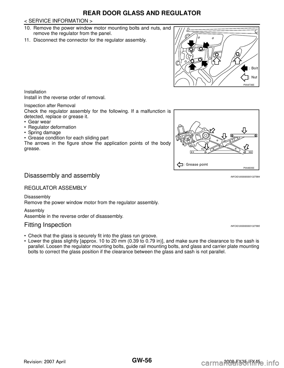
Inspection after Removal
Check the regulator assembly for the following. If a malfunction is
detected, replace or grease it.
Gear wear
Regulator deformation
Spring damage
Grease condition for each sliding part
The arrows in the figure show the application points of the body
grease.
Disassembly and assemblyINFOID:0000000001327994
REGULATOR ASSEMBLY
Disassembly
Remove the power window motor from the regulator assembly.
Assembly
Assemble in the reverse order of disassembly.
Fitting InspectionINFOID:0000000001327995
Check that the glass is securely fit into the glass run groove.
Lower the glass slightly [approx. 10 to 20 mm (0.39 to 0.79 in)], and make sure the clearance to the sash is
parallel. Loosen the regulator mounting bolts, guide rail mounting bolts, and glass and carrier plate mounting
bolts to correct the glass position if the clearance between the glass and sash is not parallel.
PIIA4736E
PIIA4935E
3AA93ABC3ACD3AC03ACA3AC03AC63AC53A913A773A893A873A873A8E3A773A983AC73AC93AC03AC3
3A893A873A873A8F3A773A9D3AAF3A8A3A8C3A863A9D3AAF3A8B3A8C
Page 2971 of 3924
GW-58
< SERVICE INFORMATION >
INSIDE MIRROR
Removal and Installation
INFOID:0000000001327997
REMOVAL
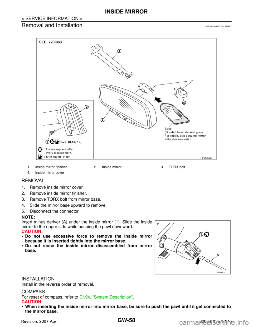
1. Remove inside mirror cover.
2. Remove inside mirror finisher.
3. Remove TORX bolt from mirror base.
4. Slide the mirror base upward to remove.
5. Disconnect the connector.
NOTE:
Insert minus deriver (A) under the inside mirror (1). Slide the inside
mirror to the upper side while pushing the pawl downward.
CAUTION:
Do not use excessive force to remove the inside mirror because it is inserted tightly into the mirror base.
Do not reuse the inside mi rror disassembled from mirror
base.
INSTALLATION
Install in the reverse order of removal.
COMPASS
For reset of compass, refer to DI-94, "System Description".
CAUTION:
When inserting the inside mirror into mirror base, be sure to push the pawl until it get connected to
the mirror base.
1. Inside mirror finisher 2. In side mirror 3. TORX bolt
4. Inside mirror cover
PIIA4934E
PIIB9501J
3AA93ABC3ACD3AC03ACA3AC03AC63AC53A913A773A893A873A873A8E3A773A983AC73AC93AC03AC3
3A893A873A873A8F3A773A9D3AAF3A8A3A8C3A863A9D3AAF3A8B3A8C
Page 2984 of 3924
REAR WINDOW DEFOGGERGW-71
< SERVICE INFORMATION >
C
DE
F
G H
J
K L
M A
B
GW
N
O P
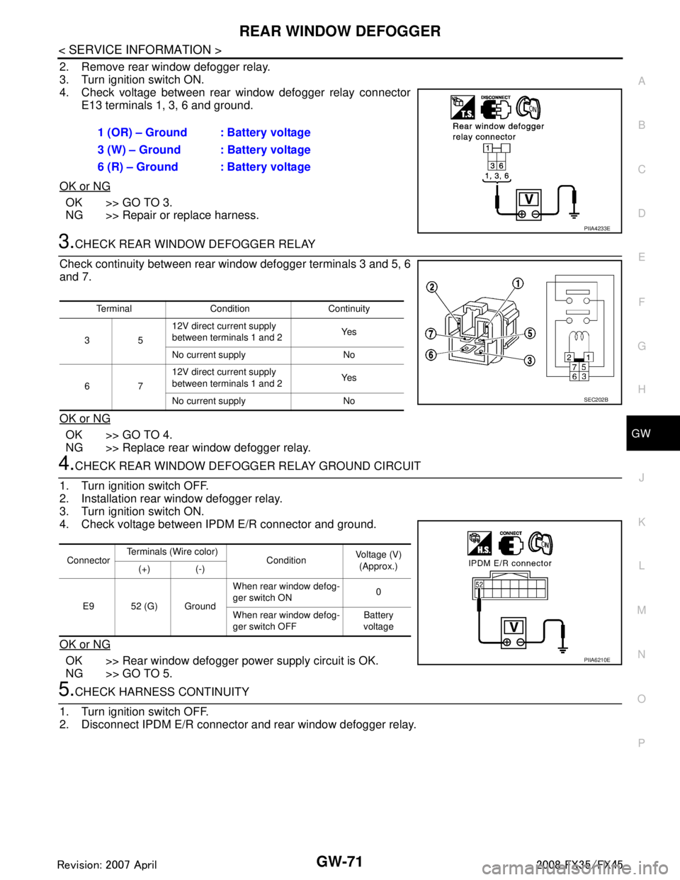
2. Remove rear window defogger relay.
3. Turn ignition switch ON.
4. Check voltage between rear window defogger relay connector E13 terminals 1, 3, 6 and ground.
OK or NG
OK >> GO TO 3.
NG >> Repair or replace harness.
3.CHECK REAR WINDOW DEFOGGER RELAY
Check continuity between rear wi ndow defogger terminals 3 and 5, 6
and 7.
OK or NG
OK >> GO TO 4.
NG >> Replace rear window defogger relay.
4.CHECK REAR WINDOW DEFOGG ER RELAY GROUND CIRCUIT
1. Turn ignition switch OFF.
2. Installation rear window defogger relay.
3. Turn ignition switch ON.
4. Check voltage between IPDM E/R connector and ground.
OK or NG
OK >> Rear window defogger power supply circuit is OK.
NG >> GO TO 5.
5.CHECK HARNESS CONTINUITY
1. Turn ignition switch OFF.
2. Disconnect IPDM E/R connector and rear window defogger relay. 1 (OR) – Ground : Battery voltage
3 (W) – Ground : Battery voltage
6 (R) – Ground : Battery voltage
PIIA4233E
Terminal Condition Continuity
35 12V direct current supply
between terminals 1 and 2
Ye s
No current supply No
67 12V direct current supply
between terminals 1 and 2
Ye s
No current supply No
SEC202B
Connector Terminals (Wire color)
ConditionVoltage (V)
(Approx.)
(+) (-)
E9 52 (G) Ground When rear window defog-
ger switch ON
0
When rear window defog-
ger switch OFF Battery
voltage
PIIA6210E
3AA93ABC3ACD3AC03ACA3AC03AC63AC53A913A773A893A873A873A8E3A773A983AC73AC93AC03AC3
3A893A873A873A8F3A773A9D3AAF3A8A3A8C3A863A9D3AAF3A8B3A8C