Page 2848 of 3924
FSU-4
< SERVICE INFORMATION >
NOISE, VIBRATION AND HARSHNESS (NVH) TROUBLESHOOTING
NOISE, VIBRATION AND HARSHNESS (NVH) TROUBLESHOOTING
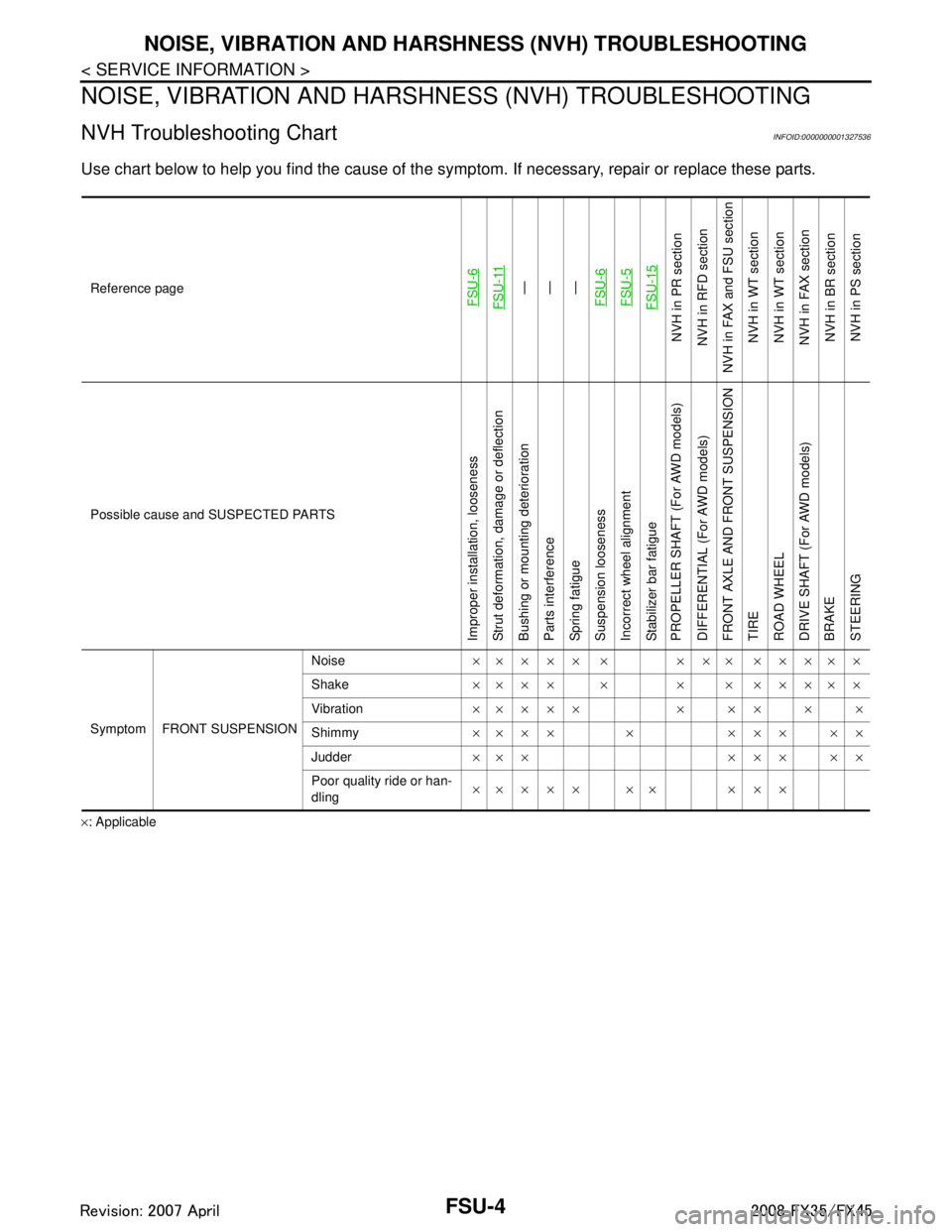
NVH Troubleshooting ChartINFOID:0000000001327536
Use chart below to help you find the cause of the symp tom. If necessary, repair or replace these parts.
×: ApplicableReference page
FSU-6FSU-11
—
—
—
FSU-6FSU-5FSU-15
NVH in PR section
NVH in RFD section
NVH in FAX and FSU section
NVH in WT section
NVH in WT section
NVH in FAX section NVH in BR sectionNVH in PS section
Possible cause and SUSPECTED PARTS
Improper installation, looseness
Strut deformation, damage or deflection
Bushing or mounting deterioration
Parts interference
Spring fatigue
Suspension looseness
Incorrect wheel alignment
Stabilizer bar fatigue
PROPELLER SHAFT (For AWD models)
DIFFERENTIAL (For AWD models)
FRONT AXLE AND FRONT SUSPENSION
TIRE
ROAD WHEEL
DRIVE SHAFT (For AWD models)
BRAKE
STEERING
Symptom FRONT SUSPENSION Noise
××××× × ××× ×××××
Shake ×××× × × × ×××××
Vibration ××××× × ×× × ×
Shimmy ×××× × ××× ××
Judder ××× ××× ××
Poor quality ride or han-
dling ×× × × × ×× × × ×
3AA93ABC3ACD3AC03ACA3AC03AC63AC53A913A773A893A873A873A8E3A773A983AC73AC93AC03AC3
3A893A873A873A8F3A773A9D3AAF3A8A3A8C3A863A9D3AAF3A8B3A8C
Page 2850 of 3924
FSU-6
< SERVICE INFORMATION >
FRONT SUSPENSION ASSEMBLY
- Use the “Jacking Compensation Method”. After installing the alignment targets or head units, raise the vehi-
cle and rotate the wheels 1/2 turn both ways.
- See Instructions in the alignment machine you're using for more information on this.
INSPECTION OF CAMBER, CASTER AND KINGPIN INCLINATION ANGLES
Camber, caster, kingpin inclination angles cannot be adjusted.
Before inspection, mount front wheels onto turning radius gauge. Mount rear wheels onto a stand that has
same height so vehicle will remain horizontal.
Removal and InstallationINFOID:0000000001327539
COMPONENTS
3AA93ABC3ACD3AC03ACA3AC03AC63AC53A913A773A893A873A873A8E3A773A983AC73AC93AC03AC3
3A893A873A873A8F3A773A9D3AAF3A8A3A8C3A863A9D3AAF3A8B3A8C
Page 2852 of 3924
FSU-8
< SERVICE INFORMATION >
FRONT SUSPENSION ASSEMBLY
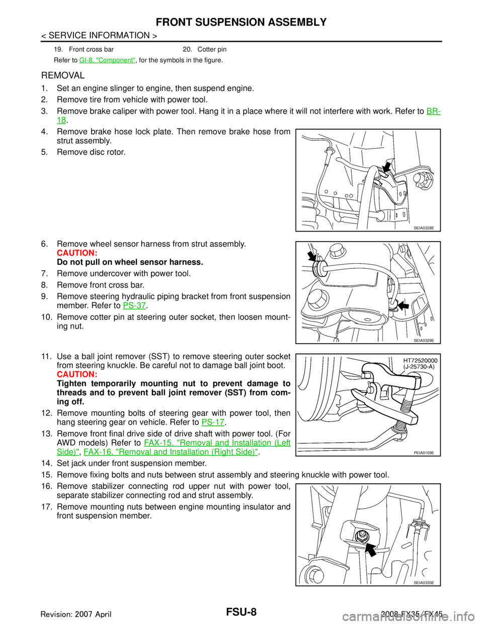
REMOVAL
1. Set an engine slinger to engine, then suspend engine.
2. Remove tire from vehicle with power tool.
3. Remove brake caliper with power tool. Hang it in a place where it will not interfere with work. Refer to BR-
18.
4. Remove brake hose lock plate. Then remove brake hose from strut assembly.
5. Remove disc rotor.
6. Remove wheel sensor harness from strut assembly. CAUTION:
Do not pull on wheel sensor harness.
7. Remove undercover with power tool.
8. Remove front cross bar.
9. Remove steering hydraulic piping bracket from front suspension member. Refer to PS-37
.
10. Remove cotter pin at steering outer socket, then loosen mount- ing nut.
11. Use a ball joint remover (SST) to remove steering outer socket from steering knuckle. Be careful not to damage ball joint boot.
CAUTION:
Tighten temporarily mounting nut to prevent damage to
threads and to prevent ball jo int remover (SST) from com-
ing off.
12. Remove mounting bolts of steering gear with power tool, then hang steering gear on vehicle. Refer to PS-17
.
13. Remove front final drive side of drive shaft with power tool. (For AWD models) Refer to FAX-15, "
Removal and Installation (Left
Side)", FAX-16, "Removal and Installation (Right Side)".
14. Set jack under front suspension member.
15. Remove fixing bolts and nuts between strut assembly and steering knuckle with power tool.
16. Remove stabilizer connecting rod upper nut with power tool, separate stabilizer connecting rod and strut assembly.
17. Remove mounting nuts between engine mounting insulator and front suspension member.
19. Front cross bar 20. Cotter pin
Refer to GI-8, "
Component", for the symbols in the figure.
SEIA0328E
SEIA0329E
PEIA0109E
SEIA0330E
3AA93ABC3ACD3AC03ACA3AC03AC63AC53A913A773A893A873A873A8E3A773A983AC73AC93AC03AC3
3A893A873A873A8F3A773A9D3AAF3A8A3A8C3A863A9D3AAF3A8B3A8C
Page 2853 of 3924
FRONT SUSPENSION ASSEMBLYFSU-9
< SERVICE INFORMATION >
C
DF
G H
I
J
K L
M A
B
FSU
N
O P
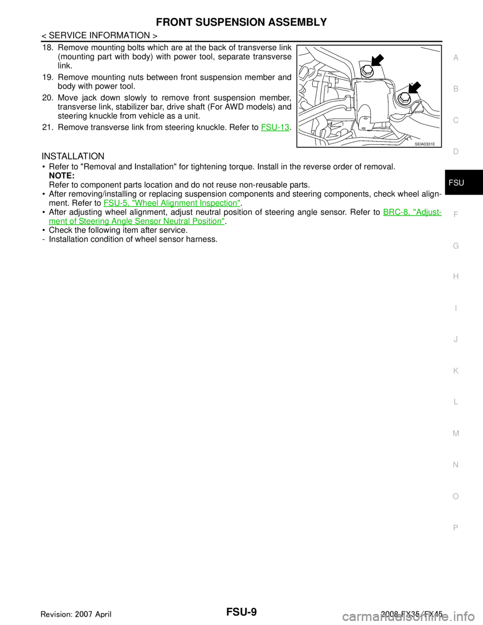
18. Remove mounting bolts which are at the back of transverse link (mounting part with body) with power tool, separate transverse
link.
19. Remove mounting nuts between front suspension member and body with power tool.
20. Move jack down slowly to remove front suspension member, transverse link, stabilizer bar, drive shaft (For AWD models) and
steering knuckle from vehicle as a unit.
21. Remove transverse link from steering knuckle. Refer to FSU-13
.
INSTALLATION
Refer to "Removal and Installation" for tightening torque. Install in the reverse order of removal.
NOTE:
Refer to component parts location and do not reuse non-reusable parts.
After removing/installing or replacing suspensi on components and steering components, check wheel align-
ment. Refer to FSU-5, "
Wheel Alignment Inspection".
After adjusting wheel alignment, adjust neutral position of steering angle sensor. Refer to BRC-8, "
Adjust-
ment of Steering Angle Sensor Neutral Position".
Check the following item after service.
- Installation condition of wheel sensor harness.
SEIA0331E
3AA93ABC3ACD3AC03ACA3AC03AC63AC53A913A773A893A873A873A8E3A773A983AC73AC93AC03AC3
3A893A873A873A8F3A773A9D3AAF3A8A3A8C3A863A9D3AAF3A8B3A8C
Page 2854 of 3924
FSU-10
< SERVICE INFORMATION >
COIL SPRING AND STRUT
COIL SPRING AND STRUT
Removal and InstallationINFOID:0000000001327540
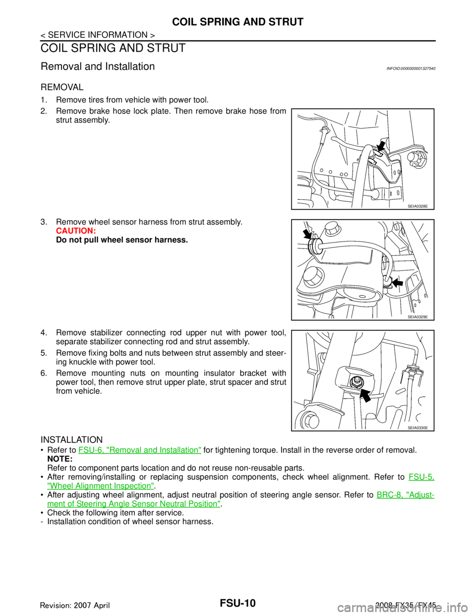
REMOVAL
1. Remove tires from vehicle with power tool.
2. Remove brake hose lock plate. Then remove brake hose fromstrut assembly.
3. Remove wheel sensor harness from strut assembly. CAUTION:
Do not pull wheel sensor harness.
4. Remove stabilizer connecting rod upper nut with power tool, separate stabilizer connecting rod and strut assembly.
5. Remove fixing bolts and nuts between strut assembly and steer- ing knuckle with power tool.
6. Remove mounting nuts on mounting insulator bracket with power tool, then remove strut upper plate, strut spacer and strut
from vehicle.
INSTALLATION
Refer to FSU-6, "Removal and Installation" for tightening torque. Install in the reverse order of removal.
NOTE:
Refer to component parts location and do not reuse non-reusable parts.
After removing/installing or replacing suspension components, check wheel alignment. Refer to FSU-5,
"Wheel Alignment Inspection".
After adjusting wheel alignment, adjust neutral position of steering angle sensor. Refer to BRC-8, "
Adjust-
ment of Steering Angle Sensor Neutral Position".
Check the following item after service.
- Installation condition of wheel sensor harness.
SEIA0328E
SEIA0329E
SEIA0330E
3AA93ABC3ACD3AC03ACA3AC03AC63AC53A913A773A893A873A873A8E3A773A983AC73AC93AC03AC3
3A893A873A873A8F3A773A9D3AAF3A8A3A8C3A863A9D3AAF3A8B3A8C
Page 2856 of 3924
FSU-12
< SERVICE INFORMATION >
COIL SPRING AND STRUT
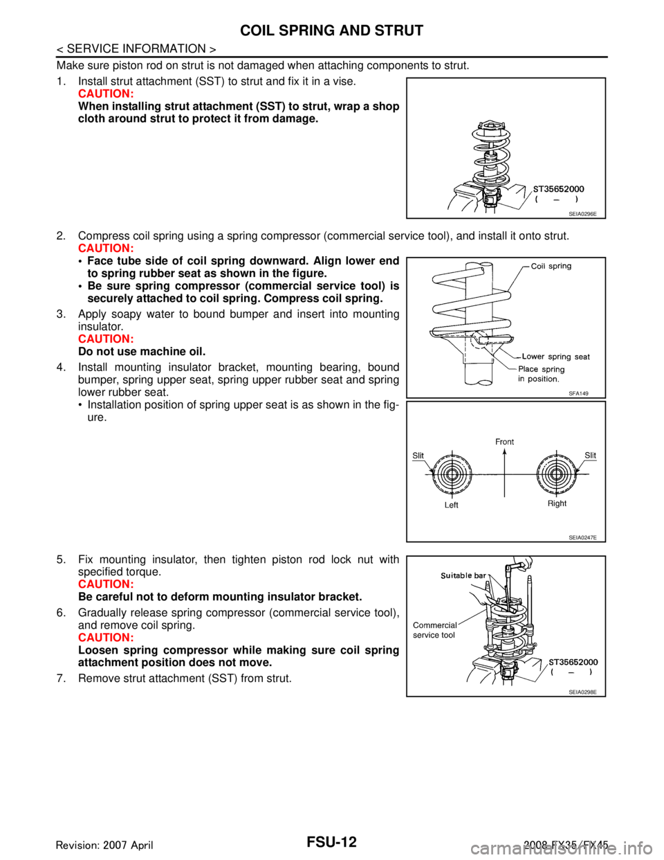
Make sure piston rod on strut is not damaged when attaching components to strut.
1. Install strut attachment (SST) to strut and fix it in a vise.CAUTION:
When installing strut attachment (SST) to strut, wrap a shop
cloth around strut to protect it from damage.
2. Compress coil spring using a spring compressor (c ommercial service tool), and install it onto strut.
CAUTION:
Face tube side of coil spri ng downward. Align lower end
to spring rubber seat as shown in the figure.
Be sure spring compressor (commercial service tool) is securely attached to coil sp ring. Compress coil spring.
3. Apply soapy water to bound bumper and insert into mounting insulator.
CAUTION:
Do not use machine oil.
4. Install mounting insulator bracket, mounting bearing, bound bumper, spring upper seat, spring upper rubber seat and spring
lower rubber seat.
Installation position of spring upper seat is as shown in the fig-ure.
5. Fix mounting insulator, then tighten piston rod lock nut with specified torque.
CAUTION:
Be careful not to deform mounting insulator bracket.
6. Gradually release spring compressor (commercial service tool), and remove coil spring.
CAUTION:
Loosen spring compressor whil e making sure coil spring
attachment position does not move.
7. Remove strut attachment (SST) from strut.
SEIA0296E
SFA149
SEIA0247E
SEIA0298E
3AA93ABC3ACD3AC03ACA3AC03AC63AC53A913A773A893A873A873A8E3A773A983AC73AC93AC03AC3
3A893A873A873A8F3A773A9D3AAF3A8A3A8C3A863A9D3AAF3A8B3A8C
Page 2857 of 3924
TRANSVERSE LINKFSU-13
< SERVICE INFORMATION >
C
DF
G H
I
J
K L
M A
B
FSU
N
O P
TRANSVERSE LINK
Removal and InstallationINFOID:0000000001327542
REMOVAL
1. Remove tire from vehicle with power tool.
2. Remove undercover with power tool.
3. Remove front cross bar.
4. Remove cotter pin at transve rse link, then loosen mounting nut.
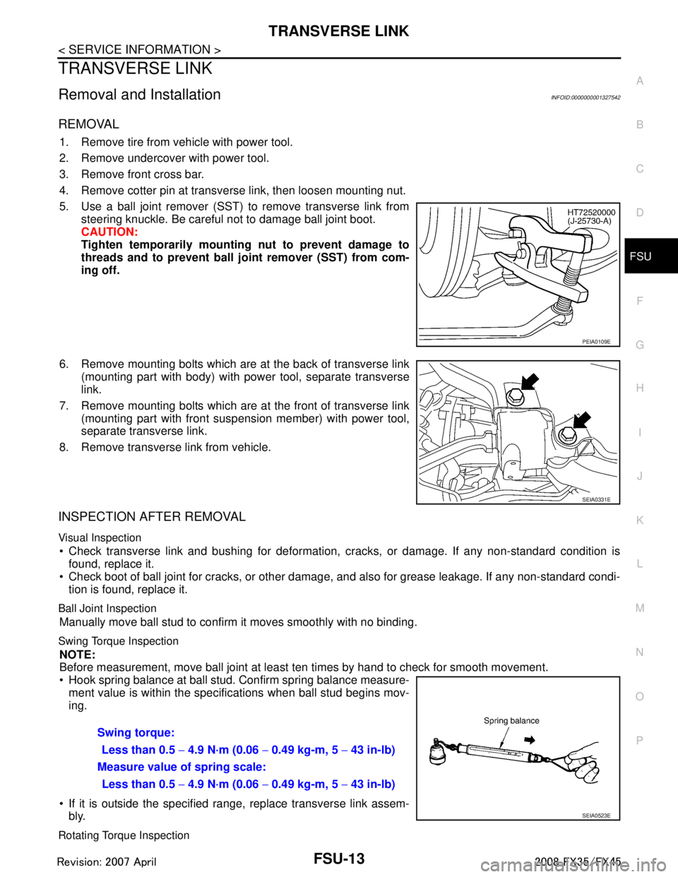
5. Use a ball joint remover (SST) to remove transverse link from steering knuckle. Be careful not to damage ball joint boot.
CAUTION:
Tighten temporarily mounting nut to prevent damage to
threads and to prevent ball jo int remover (SST) from com-
ing off.
6. Remove mounting bolts which are at the back of transverse link (mounting part with body) with power tool, separate transverse
link.
7. Remove mounting bolts which are at the front of transverse link (mounting part with front suspension member) with power tool,
separate transverse link.
8. Remove transverse link from vehicle.
INSPECTION AFTER REMOVAL
Visual Inspection
Check transverse link and bushing for deformation, cracks, or damage. If any non-standard condition is
found, replace it.
Check boot of ball joint for cracks, or other damage, and also for grease leakage. If any non-standard condi-
tion is found, replace it.
Ball Joint Inspection
Manually move ball stud to confirm it moves smoothly with no binding.
Swing Torque Inspection
NOTE:
Before measurement, move ball joint at least ten times by hand to check for smooth movement.
Hook spring balance at ball stud. Confirm spring balance measure- ment value is within the specifications when ball stud begins mov-
ing.
If it is outside the specified range, replace transverse link assem- bly.
Rotating Torque Inspection
PEIA0109E
SEIA0331E
Swing torque:
Less than 0.5 − 4.9 N·m (0.06 − 0.49 kg-m, 5 − 43 in-lb)
Measure value of spring scale: Less than 0.5 − 4.9 N·m (0.06 − 0.49 kg-m, 5 − 43 in-lb)
SEIA0523E
3AA93ABC3ACD3AC03ACA3AC03AC63AC53A913A773A893A873A873A8E3A773A983AC73AC93AC03AC3
3A893A873A873A8F3A773A9D3AAF3A8A3A8C3A863A9D3AAF3A8B3A8C
Page 2858 of 3924
FSU-14
< SERVICE INFORMATION >
TRANSVERSE LINK
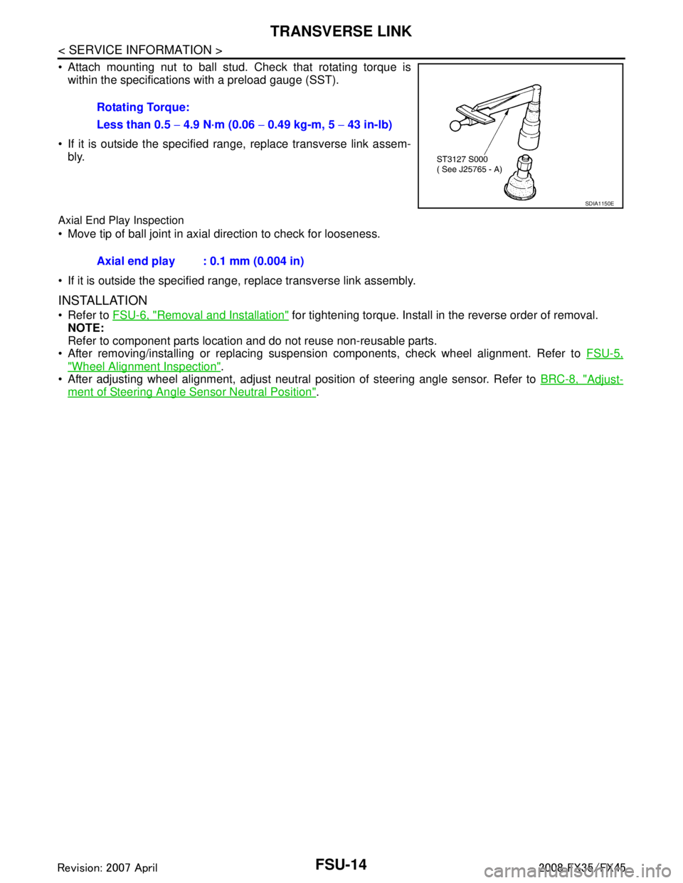
Attach mounting nut to ball stud. Check that rotating torque iswithin the specifications with a preload gauge (SST).
If it is outside the specified range, replace transverse link assem- bly.
Axial End Play Inspection
Move tip of ball joint in axial direction to check for looseness.
If it is outside the specified range, replace transverse link assembly.
INSTALLATION
Refer to FSU-6, "Removal and Installation" for tightening torque. Install in the reverse order of removal.
NOTE:
Refer to component parts location and do not reuse non-reusable parts.
After removing/installing or replacing suspension components, check wheel alignment. Refer to FSU-5,
"Wheel Alignment Inspection".
After adjusting wheel alignment, adjust neutral position of steering angle sensor. Refer to BRC-8, "
Adjust-
ment of Steering Angle Sensor Neutral Position".
Rotating Torque:
Less than 0.5
− 4.9 N·m (0.06 − 0.49 kg-m, 5 − 43 in-lb)
SDIA1150E
Axial end play : 0.1 mm (0.004 in)
3AA93ABC3ACD3AC03ACA3AC03AC63AC53A913A773A893A873A873A8E3A773A983AC73AC93AC03AC3
3A893A873A873A8F3A773A9D3AAF3A8A3A8C3A863A9D3AAF3A8B3A8C