2008 INFINITI FX35 installation
[x] Cancel search: installationPage 2859 of 3924
STABILIZER BARFSU-15
< SERVICE INFORMATION >
C
DF
G H
I
J
K L
M A
B
FSU
N
O P
STABILIZER BAR
Removal and InstallationINFOID:0000000001327543
REMOVAL
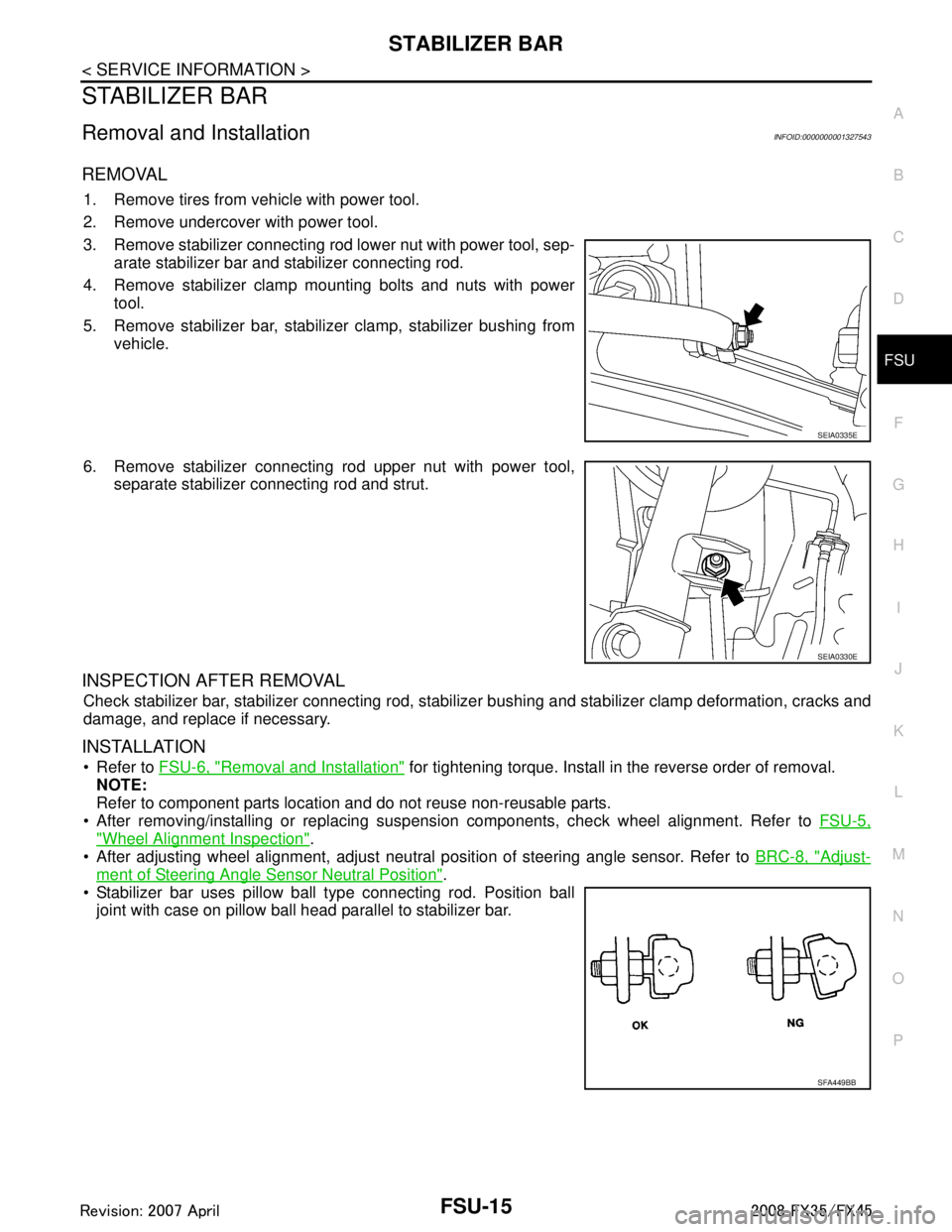
1. Remove tires from vehicle with power tool.
2. Remove undercover with power tool.
3. Remove stabilizer connecting rod lower nut with power tool, sep- arate stabilizer bar and stabilizer connecting rod.
4. Remove stabilizer clamp mounting bolts and nuts with power tool.
5. Remove stabilizer bar, stabilizer clamp, stabilizer bushing from vehicle.
6. Remove stabilizer connecting rod upper nut with power tool, separate stabilizer connecting rod and strut.
INSPECTION AFTER REMOVAL
Check stabilizer bar, stabilizer connecting rod, stabiliz er bushing and stabilizer clamp deformation, cracks and
damage, and replace if necessary.
INSTALLATION
Refer to FSU-6, "Removal and Installation" for tightening torque. Install in the reverse order of removal.
NOTE:
Refer to component parts location and do not reuse non-reusable parts.
After removing/installing or replacing suspension components, check wheel alignment. Refer to FSU-5,
"Wheel Alignment Inspection".
After adjusting wheel alignment, adjust neutral position of steering angle sensor. Refer to BRC-8, "
Adjust-
ment of Steering Angle Sensor Neutral Position".
Stabilizer bar uses pillow ball type connecting rod. Position ball
joint with case on pillow ball head parallel to stabilizer bar.
SEIA0335E
SEIA0330E
SFA449BB
3AA93ABC3ACD3AC03ACA3AC03AC63AC53A913A773A893A873A873A8E3A773A983AC73AC93AC03AC3
3A893A873A873A8F3A773A9D3AAF3A8A3A8C3A863A9D3AAF3A8B3A8C
Page 2860 of 3924
FSU-16
< SERVICE INFORMATION >
FRONT SUSPENSION MEMBER
FRONT SUSPENSION MEMBER
Removal and InstallationINFOID:0000000001327544
REMOVAL
1. Set engine slinger to engine, then suspend an engine.
2. Remove tires from vehicle with power tool.
3. Remove undercover with power tool.
4. Remove front cross bar.
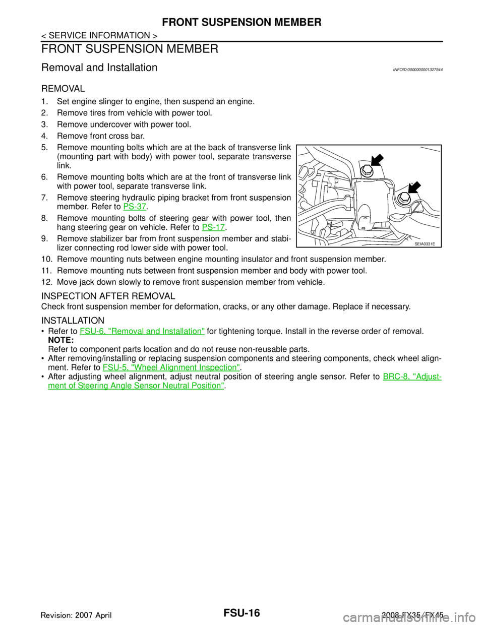
5. Remove mounting bolts which are at the back of transverse link(mounting part with body) with power tool, separate transverse
link.
6. Remove mounting bolts which are at the front of transverse link with power tool, separate transverse link.
7. Remove steering hydraulic piping bracket from front suspension member. Refer to PS-37
.
8. Remove mounting bolts of steering gear with power tool, then hang steering gear on vehicle. Refer to PS-17
.
9. Remove stabilizer bar from front suspension member and stabi- lizer connecting rod lower side with power tool.
10. Remove mounting nuts between engine mounting insulator and front suspension member.
11. Remove mounting nuts between front suspension member and body with power tool.
12. Move jack down slowly to remove front suspension member from vehicle.
INSPECTION AFTER REMOVAL
Check front suspension member for deformation, cr acks, or any other damage. Replace if necessary.
INSTALLATION
Refer to FSU-6, "Removal and Installation" for tightening torque. Install in the reverse order of removal.
NOTE:
Refer to component parts location and do not reuse non-reusable parts.
After removing/installing or replacing suspension components and steering components, check wheel align- ment. Refer to FSU-5, "
Wheel Alignment Inspection".
After adjusting wheel alignment, adjust neutral position of steering angle sensor. Refer to BRC-8, "
Adjust-
ment of Steering Angle Sensor Neutral Position".
SEIA0331E
3AA93ABC3ACD3AC03ACA3AC03AC63AC53A913A773A893A873A873A8E3A773A983AC73AC93AC03AC3
3A893A873A873A8F3A773A9D3AAF3A8A3A8C3A863A9D3AAF3A8B3A8C
Page 2864 of 3924
GI-2
< SERVICE INFORMATION >
PRECAUTIONS
SERVICE INFORMATION
PRECAUTIONS
DescriptionINFOID:0000000001325649
Observe the following precautions to ensure safe and proper servicing. These precautions are not
described in each individual section.
Precaution for Supplemental Restraint S ystem (SRS) "AIR BAG" and "SEAT BELT
PRE-TENSIONER"
INFOID:0000000001612904
The Supplemental Restraint System such as “A IR BAG” and “SEAT BELT PRE-TENSIONER”, used along
with a front seat belt, helps to reduce the risk or severi ty of injury to the driver and front passenger for certain
types of collision. This system includes seat belt switch inputs and dual stage front air bag modules. The SRS
system uses the seat belt switches to determine the front air bag deployment, and may only deploy one front
air bag, depending on the severity of a collision and w hether the front occupants are belted or unbelted.
Information necessary to service the system safely is included in the “SUPPLEMENTAL RESTRAINT SYS-
TEM” and “SEAT BELTS” of this Service Manual.
WARNING:
• To avoid rendering the SRS inopera tive, which could increase the risk of personal injury or death in
the event of a collision which would result in air bag inflation, all maintenance must be performed by
an authorized NISS AN/INFINITI dealer.
Improper maintenance, including in correct removal and installation of the SRS, can lead to personal
injury caused by unintent ional activation of the system. For re moval of Spiral Cable and Air Bag
Module, see the “SUPPLEMEN TAL RESTRAINT SYSTEM”.
Do not use electrical test equipmen t on any circuit related to the SRS unless instructed to in this
Service Manual. SRS wiring harnesses can be identi fied by yellow and/or orange harnesses or har-
ness connectors.
Precaution Necessary for Steering W heel Rotation After Battery Disconnect
INFOID:0000000001612934
NOTE:
This Procedure is applied only to models with In telligent Key system and NVIS/IVIS (NISSAN/INFINITI
VEHICLE IMMOBILIZER SYSTEM - NATS).
Remove and install all control units after disconnecting both battery cables with the ignition knob in the ″LOCK ″ position.
Always use CONSULT-III to perform self-diagnosis as a part of each function inspection after finishing work.
If DTC is detected, perform trouble diagnosis according to self-diagnostic results.
For models equipped with the Intelligent Key system and NVIS /IVIS, an electrically controlled steering lock
mechanism is adopted on the key cylinder.
For this reason, if the battery is disconnected or if the battery is discharged, the steering wheel will lock and
steering wheel rotation will become impossible.
If steering wheel rotation is required when battery pow er is interrupted, follow the procedure below before
starting the repair operation.
OPERATION PROCEDURE
1. Connect both battery cables. NOTE:
Supply power using jumper cables if battery is discharged.
2. Use the Intelligent Key or mechanical key to turn the ignition switch to the ″ACC ″ position. At this time, the
steering lock will be released.
3. Disconnect both battery cables. The steering lock will remain released and the steering wheel can be
rotated.
4. Perform the necessary repair operation.
5. When the repair work is completed, return the ignition switch to the ″LOCK ″ position before connecting
the battery cables. (At this time, the steering lock mechanism will engage.)
6. Perform a self-diagnosis check of all control units using CONSULT-III.
3AA93ABC3ACD3AC03ACA3AC03AC63AC53A913A773A893A873A873A8E3A773A983AC73AC93AC03AC3
3A893A873A873A8F3A773A9D3AAF3A8A3A8C3A863A9D3AAF3A8B3A8C
Page 2867 of 3924
PRECAUTIONSGI-5
< SERVICE INFORMATION >
C
DE
F
G H
I
J
K L
M B
GI
N
O P
Do not place the vehicle on flammable material. Keep flammable material off the exhaust pipe and the three
way catalyst.
Precaution for Fuel (Unlead ed Premium Gasoline Recommended)INFOID:0000000001325656
VQ35DE
INFINITI recommends the use of unleaded premium gasoli ne with an octane rating of at least 91 AKI (Anti-
Knock Index) number (Research octane number 96).
If unleaded premium gasoline is not available, you may use unleaded regular gasoline with an octane rating of
at least 87AKI number (Research octane number 91), but you may notice a decrease in performance.
CAUTION:
Do not use leaded gasoli ne. Using leaded gasoline will damage the three way catalyst. Do not use E-85
fuel (85% fuel ethanol, 15% unlead ed gasoline) unless the vehicle is specifically designed for E-85 fuel
(i.e. Flexible Fuel Vehicle - FFV models). Using a fu el other than that specified could adversely affect
the emission control devices and systems, and could also affect the warranty coverage validity.
Precaution for Fuel (Unleaded Premium Gasoline Required)INFOID:0000000001325657
VK45DE
Use unleaded premium gasoline with an octane rating of at least 91 AKI (Anti-Knock Index) number (Research
octane number 96).
If unleaded premium gasoline is not available, unleaded r egular gasoline with an octane rating of at least 87
AKI number (Research octane number 91) can be us ed, but only under the following precautions:
have the fuel tank filled only partially with unl eaded regular gasoline, and fill up with unleaded premium gas-
oline as soon as possible.
avoid full throttle driving and abrupt acceleration.
However, for maximum vehicle performance, the u se of unleaded premium gasoline is recommended.
CAUTION:
Do not use leaded gasoli ne. Using leaded gasoline will damage the three way catalyst. Do not use E-85
fuel (85% fuel ethanol, 15% unlead ed gasoline) unless the vehicle is specifically designed for E-85 fuel
(i.e. Flexible Fuel Vehicle - FFV models). Using a fu el other than that specified could adversely affect
the emission control devices and systems, and could also affect the warranty coverage validity.
Precaution for Multiport Fuel Inject ion System or Engine Control SystemINFOID:0000000001325658
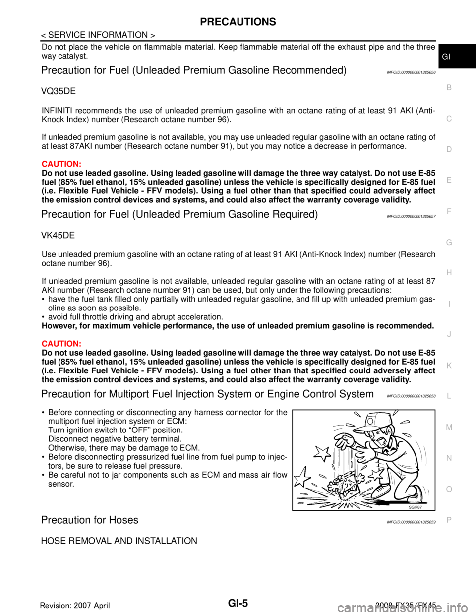
Before connecting or disconnecti ng any harness connector for the
multiport fuel injection system or ECM:
Turn ignition switch to “OFF” position.
Disconnect negative battery terminal.
Otherwise, there may be damage to ECM.
Before disconnecting pressurized fuel line from fuel pump to injec- tors, be sure to release fuel pressure.
Be careful not to jar components such as ECM and mass air flow sensor.
Precaution for HosesINFOID:0000000001325659
HOSE REMOVAL AND INSTALLATION
SGI787
3AA93ABC3ACD3AC03ACA3AC03AC63AC53A913A773A893A873A873A8E3A773A983AC73AC93AC03AC3
3A893A873A873A8F3A773A9D3AAF3A8A3A8C3A863A9D3AAF3A8B3A8C
Page 2870 of 3924
GI-8
< SERVICE INFORMATION >
HOW TO USE THIS MANUAL
HOW TO USE THIS MANUAL
DescriptionINFOID:0000000001325663
This volume explains “Removal, Disassembly, Installation, Inspection and Adjustment” and “Trouble Diag-
noses”.
Te r m sINFOID:0000000001325664
The captions WARNING and CAUTION warn you of steps that must be followed to prevent personal injury
and/or damage to some part of the vehicle.
WARNING indicates the possibility of personal in jury if instructions are not followed.
CAUTION indicates the possibility of component damage if instructions are not followed.
BOLD TYPED STATEMENTS except WARNI NG and CAUTION give you helpful information.
Standard value:Tolerance at inspection and adjustment.
Limit value:The maximum or minimum limit value t hat should not be exceeded at inspection and adjustment.
UnitsINFOID:0000000001325665
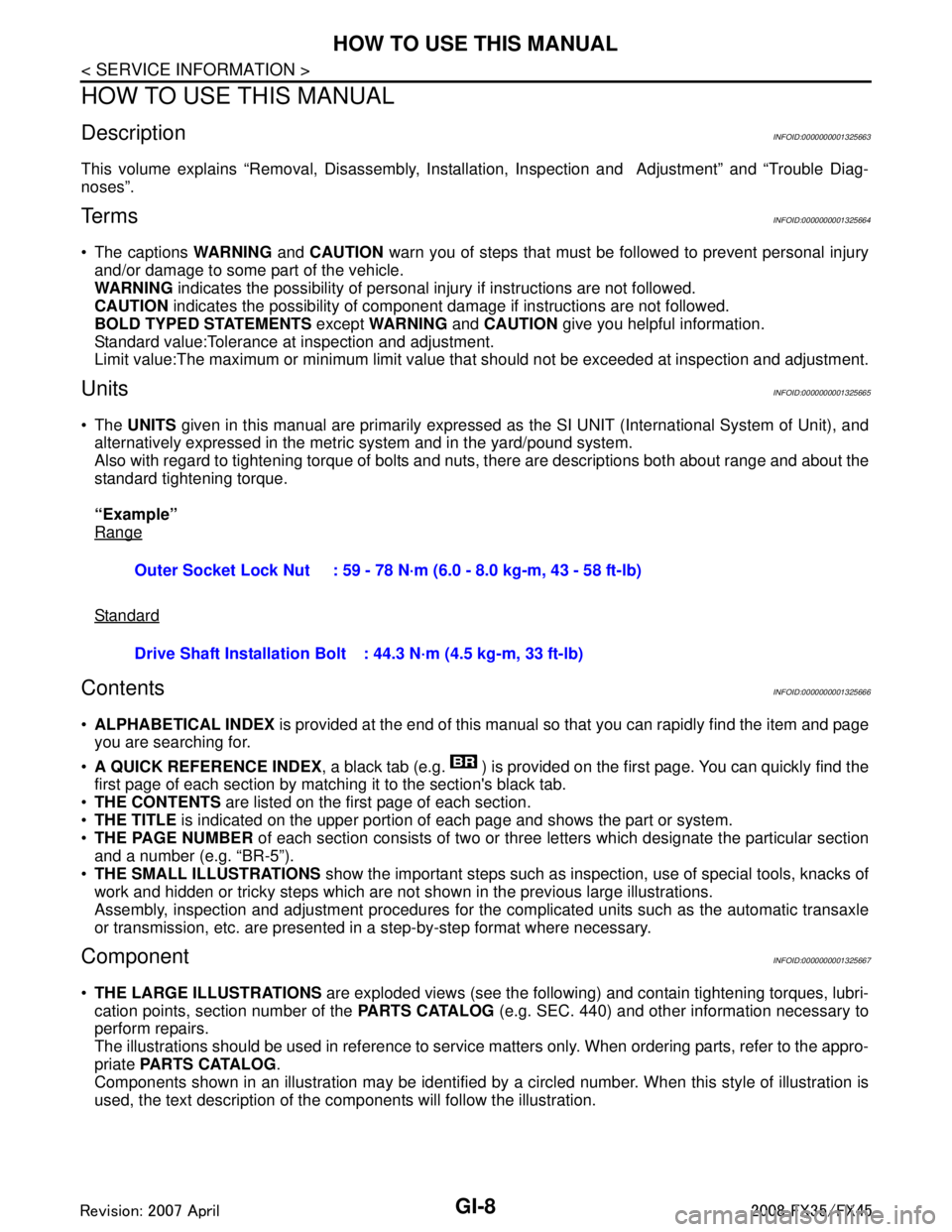
The UNITS given in this manual are primarily expressed as the SI UNIT (International System of Unit), and
alternatively expressed in the metric system and in the yard/pound system.
Also with regard to tightening torque of bolts and nuts, there are descriptions both about range and about the
standard tightening torque.
“Example”
Range
Standard
ContentsINFOID:0000000001325666
ALPHABETICAL INDEX is provided at the end of this manual so that you can rapidly find the item and page
you are searching for.
A QUICK REFERENCE INDEX , a black tab (e.g. ) is provided on t he first page. You can quickly find the
first page of each section by matching it to the section's black tab.
THE CONTENTS are listed on the first page of each section.
THE TITLE is indicated on the upper portion of eac h page and shows the part or system.
THE PAGE NUMBER of each section consists of two or three letters which designate the particular section
and a number (e.g. “BR-5”).
THE SMALL ILLUSTRATIONS show the important steps such as inspection, use of special tools, knacks of
work and hidden or tricky steps which are not shown in the previous large illustrations.
Assembly, inspection and adjustment procedures for the complicated units such as the automatic transaxle
or transmission, etc. are presented in a step-by-step format where necessary.
ComponentINFOID:0000000001325667
THE LARGE ILLUSTRATIONS are exploded views (see the following) and contain tightening torques, lubri-
cation points, section number of the PARTS CATALOG (e.g. SEC. 440) and other information necessary to
perform repairs.
The illustrations should be used in reference to service matters only. When ordering parts, refer to the appro-
priate PARTS CATALOG .
Components shown in an illustration may be identified by a circled number. When this style of illustration is
used, the text description of the components will follow the illustration. Outer Socket Lock Nut : 59 - 78 N·m (6.0 - 8.0 kg-m, 43 - 58 ft-lb)
Drive Shaft Installation Bolt
: 44.3 N·m (4.5 kg-m, 33 ft-lb)
3AA93ABC3ACD3AC03ACA3AC03AC63AC53A913A773A893A873A873A8E3A773A983AC73AC93AC03AC3
3A893A873A873A8F3A773A9D3AAF3A8A3A8C3A863A9D3AAF3A8B3A8C
Page 2888 of 3924
GI-26
< SERVICE INFORMATION >
SERVICE INFORMATION FOR ELECTRICAL INCIDENT
Cold or hot start up
Get a thorough description of the incident from the customer. It is important for simulating the conditions of the
problem.
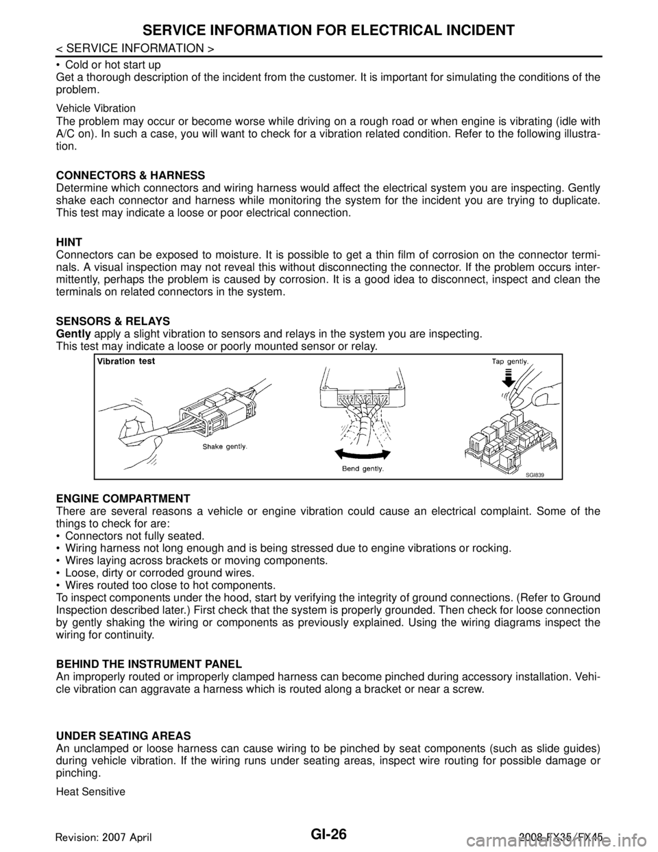
Vehicle Vibration
The problem may occur or become worse while drivi ng on a rough road or when engine is vibrating (idle with
A/C on). In such a case, you will want to check for a vi bration related condition. Refer to the following illustra-
tion.
CONNECTORS & HARNESS
Determine which connectors and wiring harness would affect the electrical system you are inspecting. Gently
shake each connector and harness while monitoring the sy stem for the incident you are trying to duplicate.
This test may indicate a loose or poor electrical connection.
HINT
Connectors can be exposed to moisture. It is possible to get a thin film of corrosion on the connector termi-
nals. A visual inspection may not reveal this without disconnecting the connector. If the problem occurs inter-
mittently, perhaps the problem is caused by corrosion. It is a good idea to disconnect, inspect and clean the
terminals on related connectors in the system.
SENSORS & RELAYS
Gently apply a slight vibration to sensors and relays in the system you are inspecting.
This test may indicate a loose or poorly mounted sensor or relay.
ENGINE COMPARTMENT
There are several reasons a vehicle or engine vibration could cause an e\
lectrical complaint. Some of the
things to check for are:
Connectors not fully seated.
Wiring harness not long enough and is being stressed due to engine vibrations or rocking.
Wires laying across brackets or moving components.
Loose, dirty or corroded ground wires.
Wires routed too close to hot components.
To inspect components under the hood, start by verifyi ng the integrity of ground connections. (Refer to Ground
Inspection described later.) First check that the system is properly grounded. Then check for loose connection
by gently shaking the wiring or components as previous ly explained. Using the wiring diagrams inspect the
wiring for continuity.
BEHIND THE INSTRUMENT PANEL
An improperly routed or improperly clamped harness can become pinched during accessory installation. Vehi-
cle vibration can aggravate a harness which is routed along a bracket or near a screw.
UNDER SEATING AREAS
An unclamped or loose harness can cause wiring to be pinched by seat components (such as slide guides)
during vehicle vibration. If the wiring runs under s eating areas, inspect wire routing for possible damage or
pinching.
Heat Sensitive
SGI839
3AA93ABC3ACD3AC03ACA3AC03AC63AC53A913A773A893A873A873A8E3A773A983AC73AC93AC03AC3
3A893A873A873A8F3A773A9D3AAF3A8A3A8C3A863A9D3AAF3A8B3A8C
Page 2893 of 3924
SERVICE INFORMATION FOR ELECTRICAL INCIDENTGI-31
< SERVICE INFORMATION >
C
DE
F
G H
I
J
K L
M B
GI
N
O P
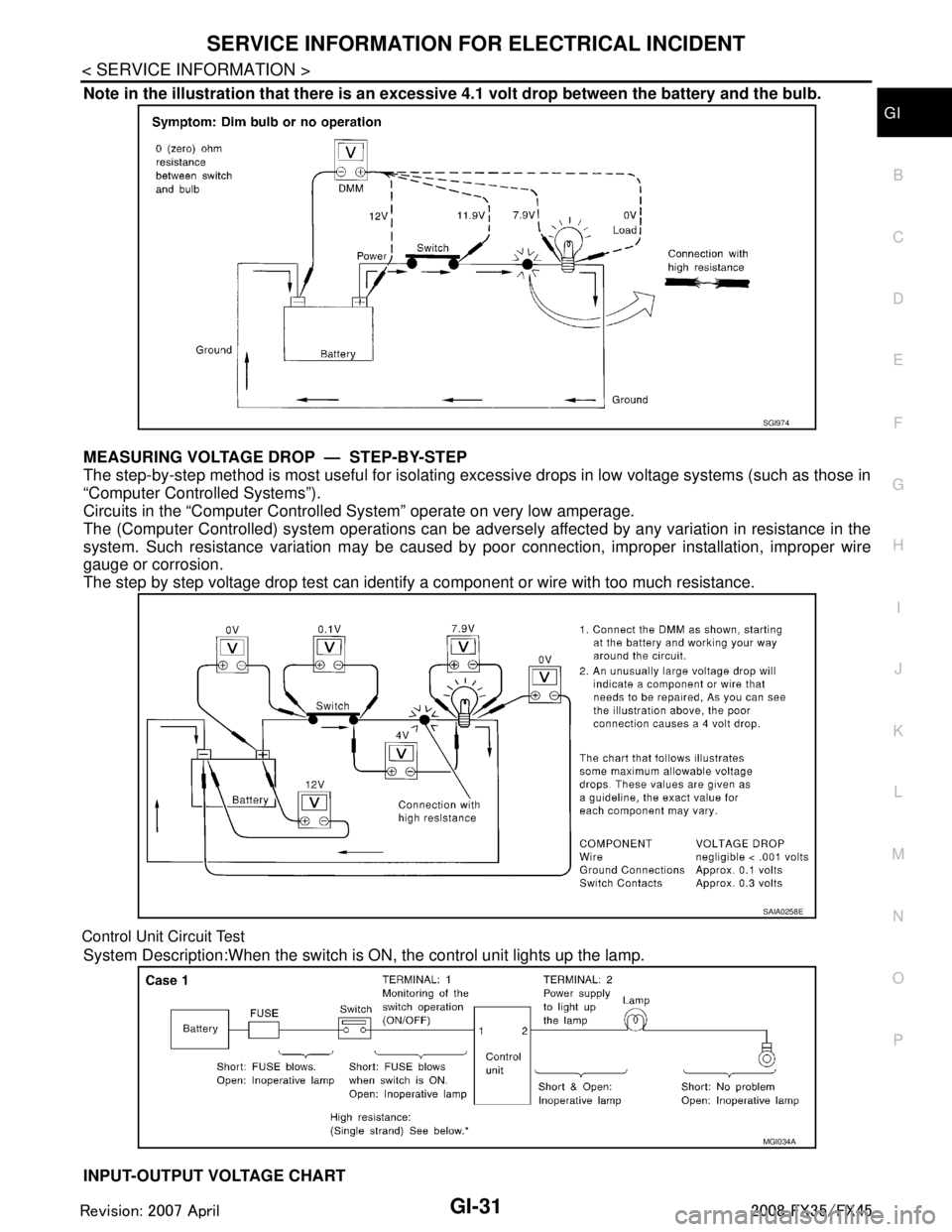
Note in the illustration that there is an excessi ve 4.1 volt drop between the battery and the bulb.
MEASURING VOLTAGE DRO P — STEP-BY-STEP
The step-by-step method is most useful for isolating ex cessive drops in low voltage systems (such as those in
“Computer Controlled Systems”).
Circuits in the “Computer Controlled System” operate on very low amperage.
The (Computer Controlled) system oper ations can be adversely affected by any variation in resistance in the
system. Such resistance variation may be caused by poor connection, improper installation, improper wire
gauge or corrosion.
The step by step voltage drop test can identify a component or wire with too much resistance.
Control Unit Circuit Test
System Description:When the switch is ON, the control unit lights up the lamp.
INPUT-OUTPUT VOLTAGE CHART
SGI974
SAIA0258E
MGI034A
3AA93ABC3ACD3AC03ACA3AC03AC63AC53A913A773A893A873A873A8E3A773A983AC73AC93AC03AC3
3A893A873A873A8F3A773A9D3AAF3A8A3A8C3A863A9D3AAF3A8B3A8C
Page 2914 of 3924
GW-1
BODY
C
DE
F
G H
J
K L
M
SECTION GW
A
B
GW
N
O P
CONTENTS
GLASSES, WINDOW SYSTEM & MIRRORS
SERVICE INFORMATION .. ..........................3
PRECAUTIONS .............................................. .....3
Precaution for Supplemental Restraint System
(SRS) "AIR BAG" and "SEAT BELT PRE-TEN-
SIONER" ............................................................. ......
3
Precaution for Procedure without Cowl Top Cover ......3
Handling for Adhesive and Primer ............................3
PREPARATION ...................................................4
Special Service Tool ........................................... ......4
Commercial Service Tool ..........................................4
SQUEAK AND RATTLE TROUBLE DIAG-
NOSES ................................................................
5
Work Flow ........................................................... ......5
Generic Squeak and Rattle Troubleshooting ............7
Diagnostic Worksheet ...............................................9
WINDSHIELD GLASS ........................................11
Removal and Installation ..................................... ....11
BACK DOOR WINDOW GLASS ........................13
Removal and Installation ..................................... ....13
POWER WINDOW SYSTEM ..............................15
Component Parts and Harness Connector Loca-
tion ...................................................................... ....
15
System Description .................................................15
CAN Communication System Description ...............18
CAN Communication Unit .......................................19
Schematic ...............................................................19
Wiring Diagram - WINDOW - ..................................20
Terminal and Reference Value for BCM .................23
Terminal and Reference Value for Power Window
Main Switch .............................................................
24
Terminal and Reference Value for Front Power
Window Switch (Passenger Side) ...........................
25
CONSULT-III Function ............................................26
Work Flow ...............................................................27
Trouble Diagnosis Symptom Chart .........................27
Check BCM Power Supply and Ground Circuit .......28
Check Power Window Main Switch Power Supply
Circuit .................................................................. ....
28
Check Front Power Window Switch (Passenger
Side) Power Supply and Ground Circuit ..................
30
Check Front Power Window Motor (Driver Side)
Circuit ......................................................................
30
Check Front Power Window Motor (Passenger
Side) Circuit .............................................................
31
Check rear Power Window Motor (LH) Circuit .........32
Check Rear Power Window Motor (RH) Circuit .......34
Check Limit Switch Circuit (Driver Side) .............. ....36
Check Limit Switch Circuit (Passenger Side) ..........37
Check Encoder Circuit (Driver Side) ........................39
Check Encoder Circuit (Passenger Side) ................40
Check Door Switch ..................................................42
Check Front Door Key Cylinder Switch ...................43
Check Power Window Serial Link (Passenger
Side) ........................................................................
45
Check Power Window Lock Switch .........................46
SIDE WINDOW GLASS ....................................48
Removal and Installation .........................................48
FRONT DOOR GLASS AND REGULATOR .....50
Removal and Installation .........................................50
Disassembly and assembly .....................................52
Inspection after Installation ......................................52
REAR DOOR GLASS AND REGULATOR .......54
Removal and Installation .........................................54
Disassembly and assembly .....................................56
Fitting Inspection .....................................................56
INSIDE MIRROR ...............................................57
Wiring Diagram - I/MIRR - .......................................57
Removal and Installation .........................................58
REAR WINDOW DEFOGGER ..........................60
Component Parts and Harness Connector Loca-
tion ...........................................................................
60
System Description ..................................................60
CAN Communication System Description ...............61
3AA93ABC3ACD3AC03ACA3AC03AC63AC53A913A773A893A873A873A8E3A773A983AC73AC93AC03AC3
3A893A873A873A8F3A773A9D3AAF3A8A3A8C3A863A9D3AAF3A8B3A8C