2008 INFINITI FX35 installation
[x] Cancel search: installationPage 2782 of 3924
![INFINITI FX35 2008 Service Manual
FRONT DRIVE SHAFTFAX-17
< SERVICE INFORMATION > [AWD]
C
EF
G H
I
J
K L
M A
B
FA X
N
O P
Removal
1. Remove tires from vehicle with power tool.
2. Remove undercover with power tool.
3. Remove cotter pi INFINITI FX35 2008 Service Manual
FRONT DRIVE SHAFTFAX-17
< SERVICE INFORMATION > [AWD]
C
EF
G H
I
J
K L
M A
B
FA X
N
O P
Removal
1. Remove tires from vehicle with power tool.
2. Remove undercover with power tool.
3. Remove cotter pi](/manual-img/42/57017/w960_57017-2781.png)
FRONT DRIVE SHAFTFAX-17
< SERVICE INFORMATION > [AWD]
C
EF
G H
I
J
K L
M A
B
FA X
N
O P
Removal
1. Remove tires from vehicle with power tool.
2. Remove undercover with power tool.
3. Remove cotter pin. Then remove lock nut from drive shaft with power tool.
4. Remove wheel sensor harness fr om strut assembly. Refer to BRC-52
.
CAUTION:
Do not pull on wheel sensor harness.
5. Remove brake hose lock prate. Then remove brake hose from strut assembly. Refer to BR-10
.
6. Remove fixing bolts and nuts between strut assembly and steering knuckle with power tool.
7. Using a puller (suitable tool), remove drive shaft from steering knuckle.
CAUTION:
When removing drive shaf t, do not apply an excessive
angle to drive shaft joint. Al so be careful not to excessively
extend slide joint.
8. Pry off drive shaft from front final drive assembly side as shown in the figure.
INSPECTION AFTER REMOVAL
Move joint up/down, left/right, and in the axial directi on. Check for any rough movement or significant loose-
ness.
Check boot for cracks or other damage, and also for grease leak- age.
If a trouble is found, disassemble drive shaft, and then replace with
new one.
INSTALLATION
Refer to "Removal and installation (Right Side)" for ti ghtening torque. Install in the reverse order of removal.
NOTE:
Refer to component parts location and do not reuse non-reusable parts.
Check the following item after service.
- Installation condition of wheel sensor harness.
SDIA0972J
SDIA1489E
SFA108A
3AA93ABC3ACD3AC03ACA3AC03AC63AC53A913A773A893A873A873A8E3A773A983AC73AC93AC03AC3
3A893A873A873A8F3A773A9D3AAF3A8A3A8C3A863A9D3AAF3A8B3A8C
Page 2786 of 3924
![INFINITI FX35 2008 Service Manual
FRONT DRIVE SHAFTFAX-21
< SERVICE INFORMATION > [AWD]
C
EF
G H
I
J
K L
M A
B
FA X
N
O P
7. Install housing to spider assembly. Apply Nissan genuine grease or equivalent to housing.
8. Install boot se INFINITI FX35 2008 Service Manual
FRONT DRIVE SHAFTFAX-21
< SERVICE INFORMATION > [AWD]
C
EF
G H
I
J
K L
M A
B
FA X
N
O P
7. Install housing to spider assembly. Apply Nissan genuine grease or equivalent to housing.
8. Install boot se](/manual-img/42/57017/w960_57017-2785.png)
FRONT DRIVE SHAFTFAX-21
< SERVICE INFORMATION > [AWD]
C
EF
G H
I
J
K L
M A
B
FA X
N
O P
7. Install housing to spider assembly. Apply Nissan genuine grease or equivalent to housing.
8. Install boot securely into grooves (indicated by *marks) shown in the figure.
CAUTION:
If there is grease on boot mo unting surfaces (indicated by *
marks) of shaft and housing, boot may come off. Remove
all grease from surfaces.
9. Make sure boot installation length “L
1 L2” is the length indicated
below. Insert a flat-bladed screwdriver or similar tool into smaller
side of boot. Bleed air from boot to prevent boot deformation.
CAUTION:
Boot may break if boot installation le ngth is less than standard value.
Take care not to touch the tip of screw driver to inside surface of boot.
10. Install new larger and smaller boot bands securely. NOTE:
Discard old boot bands; replace with new ones.
11. After installing housing and shaft, rotate boot to check whether or not the actual position is correc t. If boot position is not correct,
secure boot with new boot bands again.
12. Install circular clip. NOTE:
Discard old circular clip; replace with new one.
Wheel Side
Assemble in steps 14 to 23 of FAX-13, "On-Vehicle Inspection".
Disassembly and Assembly (Right Side)INFOID:0000000001327519
COMPONENTS
Grease amount : 95 − 105 g (3.35 − 3.70 oz)
SDIA1445E
Boot installation Length “L1 L2”:
VK45DE models (L
1) : 95 − 97 mm (3.74 − 3.82 in)
VQ35DE models (L
2) : 150.9 − 152.9 mm (5.94 − 6.02 in)
PDIA1255E
SFA395
3AA93ABC3ACD3AC03ACA3AC03AC63AC53A913A773A893A873A873A8E3A773A983AC73AC93AC03AC3
3A893A873A873A8F3A773A9D3AAF3A8A3A8C3A863A9D3AAF3A8B3A8C
Page 2789 of 3924
![INFINITI FX35 2008 Service Manual
FAX-24
< SERVICE INFORMATION >[AWD]
FRONT DRIVE SHAFT
3. Line up alignment marks which were made when spider assem-
bly was removed. Install spider assembly, with serration chamfer
facing dive shaft. INFINITI FX35 2008 Service Manual
FAX-24
< SERVICE INFORMATION >[AWD]
FRONT DRIVE SHAFT
3. Line up alignment marks which were made when spider assem-
bly was removed. Install spider assembly, with serration chamfer
facing dive shaft.](/manual-img/42/57017/w960_57017-2788.png)
FAX-24
< SERVICE INFORMATION >[AWD]
FRONT DRIVE SHAFT
3. Line up alignment marks which were made when spider assem-
bly was removed. Install spider assembly, with serration chamfer
facing dive shaft.
4. Secure spider assembly with snap ring. NOTE:
Discard old snap ring; replace with new one.
5. Apply Nissan genuine grease or equivalent to spider assembly and sliding surface.
6. Install housing to spider assembly. Apply Nissan genuine grease or equivalent to housing.
7. Install boot securely into grooves (indicated by * marks) shown in the figure.
CAUTION:
If there is grease on boot mo unting surfaces (indicated by*
marks) of shaft and housing, boot may come off. Remove
all grease from surfaces.
8. Make sure boot installation length “L” is the length indicated below. Insert a flat-bladed screwdriver or similar tool into smaller
side of boot. Bleed air from boot to prevent boot deformation.
CAUTION:
Boot may break if boot installation length is less than standard value.
Take care not to touch the tip of screw driver to inside surface of boot.
9. Install new larger and smaller boot bands securely. NOTE:
Discard old boot bands; replace with new ones.
SDIA2629E
SFA023A
Grease amount : 113 − 123 g (3.98 − 4.33 oz)
SDIA1446E
Boot installation Length “L”:
157.55 − 159.55 mm (6.20 − 6.28 in)SDIA3250E
3AA93ABC3ACD3AC03ACA3AC03AC63AC53A913A773A893A873A873A8E3A773A983AC73AC93AC03AC3
3A893A873A873A8F3A773A9D3AAF3A8A3A8C3A863A9D3AAF3A8B3A8C
Page 2790 of 3924
![INFINITI FX35 2008 Service Manual
FRONT DRIVE SHAFTFAX-25
< SERVICE INFORMATION > [AWD]
C
EF
G H
I
J
K L
M A
B
FA X
N
O P
10. Put boot band in the groove on drive shaft boot. Then fit pawls ( ) into holes to temporary installation.
N INFINITI FX35 2008 Service Manual
FRONT DRIVE SHAFTFAX-25
< SERVICE INFORMATION > [AWD]
C
EF
G H
I
J
K L
M A
B
FA X
N
O P
10. Put boot band in the groove on drive shaft boot. Then fit pawls ( ) into holes to temporary installation.
N](/manual-img/42/57017/w960_57017-2789.png)
FRONT DRIVE SHAFTFAX-25
< SERVICE INFORMATION > [AWD]
C
EF
G H
I
J
K L
M A
B
FA X
N
O P
10. Put boot band in the groove on drive shaft boot. Then fit pawls ( ) into holes to temporary installation.
NOTE:
For the large diameter side, fit projection (A) and guide slit (B) at
first.
11. Pinch projection on the band with suitable pliers to tighten band.
12. Insert tip of band below end of the pawl.
13. After installing housing and shaft, rotate boot to check whether or not the actual position is correc t. If boot position is not correct,
secure boot with new boot bands again.
14. Install circular clip. NOTE:
Discard old circular clip; replace with new one.
Wheel Side
Assemble in steps 14 to 23 of FAX-13, "On-Vehicle Inspection".
SDIA3557E
SDIA3558E
3AA93ABC3ACD3AC03ACA3AC03AC63AC53A913A773A893A873A873A8E3A773A983AC73AC93AC03AC3
3A893A873A873A8F3A773A9D3AAF3A8A3A8C3A863A9D3AAF3A8B3A8C
Page 2792 of 3924

FFD-1
DRIVELINE/AXLE
CEF
G H
I
J
K L
M
SECTION FFD
A
B
FFD
N
O P
CONTENTS
FRONT FINAL DRIVE
SERVICE INFORMATION .. ..........................2
PRECAUTIONS .............................................. .....2
Service Notice or Precaution ............................... ......2
PREPARATION ...................................................3
Special Service Tool ........................................... ......3
Commercial Service Tool ..........................................5
NOISE, VIBRATION AND HARSHNESS
(NVH) TROUBLESHOOTING .............................
6
NVH Troubleshooting Chart ................................ ......6
DESCRIPTION ....................................................7
Cross-Sectional View .......................................... ......7
DIFFERENTIAL GEAR OIL .................................8
Changing Differential Gear Oil ............................ ......8
Checking Differential Gear Oil ............................. .....8
FRONT OIL SEAL ..............................................9
Removal and Installation ..........................................9
SIDE OIL SEAL .................................................12
Removal and Installation .........................................12
FRONT FINAL DRIVE ASSEMBLY ..................14
Removal and Installation (VQ35DE Models) ...........14
Removal and Installation (VK45DE Models) ...........15
Disassembly and Assembly .....................................17
SERVICE DATA AND SPECIFICATIONS
(SDS) .................................................................
39
General Specification ..............................................39
Inspection and Adjustment ......................................39
3AA93ABC3ACD3AC03ACA3AC03AC63AC53A913A773A893A873A873A8E3A773A983AC73AC93AC03AC3
3A893A873A873A8F3A773A9D3AAF3A8A3A8C3A863A9D3AAF3A8B3A8C
Page 2793 of 3924

FFD-2
< SERVICE INFORMATION >
PRECAUTIONS
SERVICE INFORMATION
PRECAUTIONS
Service Notice or PrecautionINFOID:0000000001327476
• Check for the correct installation status prior to removal or disassembly. If matching marks are required, becertain they do not interfere with the function of the parts when applied.
Overhaul should be done in a clean work area, it is preferable to work in dustproof area.
Before disassembly, using steam or white gasoline, completely remove sand and mud from the exterior of
the unit, preventing them from entering into the unit during disassembly or assembly.
Check appearance of the disassembled parts for dam age, deformation, and unusual wear. Replace them
with a new ones if necessary.
Gaskets, seals and O-rings should be replaced any time when the unit is disassembled.
In principle, tighten bolts or nuts gradually in several steps working diagonally from inside to outside. If tight-
ening sequence is specified, observe it.
Clean and flush the parts sufficiently and blow-dry them.
Be careful not to damage sliding surfaces and mating surfaces.
When applying sealant, remove the old sealant from t he mounting surface; then remove any moisture, oil,
and foreign materials from the application and mounting surfaces.
Always use shop paper for cleaning the inside of components.
Avoid using cotton gloves or shop rags to prevent entering of lint.
During assembly, observe the specified tightening tor que, and apply new gear oil, petroleum jelly, or multi-
purpose grease as specified for each vehicle, if necessary.
3AA93ABC3ACD3AC03ACA3AC03AC63AC53A913A773A893A873A873A8E3A773A983AC73AC93AC03AC3
3A893A873A873A8F3A773A9D3AAF3A8A3A8C3A863A9D3AAF3A8B3A8C
Page 2800 of 3924

FRONT OIL SEALFFD-9
< SERVICE INFORMATION >
CEF
G H
I
J
K L
M A
B
FFD
N
O P
FRONT OIL SEAL
Removal and InstallationINFOID:0000000001327483
REMOVAL
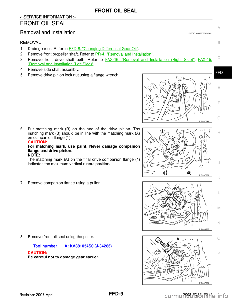
1. Drain gear oil. Refer to FFD-8, "Changing Differential Gear Oil".
2. Remove front propeller shaft. Refer to PR-4, "
Removal and Installation".
3. Remove front drive shaft both. Refer to FAX-16, "
Removal and Installation (Right Side)", FAX-15,
"Removal and Installation (Left Side)".
4. Remove side shaft assembly.
5. Remove drive pinion lock nut using a flange wrench.
6. Put matching mark (B) on the end of the drive pinion. The matching mark (B) should be in line with the matching mark (A)
on companion flange (1).
CAUTION:
For matching mark, use pain t. Never damage companion
flange and drive pinion.
NOTE:
The matching mark (A) on the final drive companion flange (1)
indicates the maximum vertical runout position.
7. Remove companion flange using a puller.
8. Remove front oil seal using the puller. CAUTION:
Be careful not to damage gear carrier.
PDIA0784J
PDIA0783J
PDIA0652E
Tool number A: KV381054S0 (J-34286)
PDIA0785J
3AA93ABC3ACD3AC03ACA3AC03AC63AC53A913A773A893A873A873A8E3A773A983AC73AC93AC03AC3
3A893A873A873A8F3A773A9D3AAF3A8A3A8C3A863A9D3AAF3A8B3A8C
Page 2801 of 3924

FFD-10
< SERVICE INFORMATION >
FRONT OIL SEAL
INSTALLATION
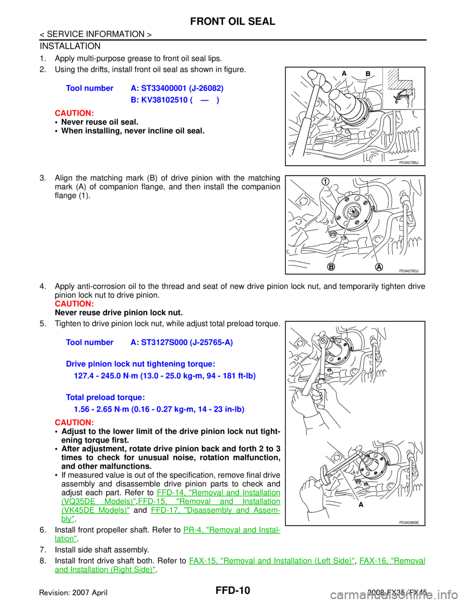
1. Apply multi-purpose grease to front oil seal lips.
2. Using the drifts, install front oil seal as shown in figure.CAUTION:
• Never reuse oil seal.
When installing, n ever incline oil seal.
3. Align the matching mark (B) of drive pinion with the matching mark (A) of companion flange, and then install the companion
flange (1).
4. Apply anti-corrosion oil to the thread and seat of new drive pinion lock nut, and temporarily tighten drive
pinion lock nut to drive pinion.
CAUTION:
Never reuse drive pinion lock nut.
5. Tighten to drive pinion lock nut, while adjust total preload torque.
CAUTION:
Adjust to the lower limit of the drive pinion lock nut tight-
ening torque first.
After adjustment, rotate dri ve pinion back and forth 2 to 3
times to check for unusual no ise, rotation malfunction,
and other malfunctions.
If measured value is out of the specification, remove final drive assembly and disassemble drive pinion parts to check and
adjust each part. Refer to FFD-14, "
Removal and Installation
(VQ35DE Models)",FFD-15, "Removal and Installation
(VK45DE Models)" and FFD-17, "Disassembly and Assem-
bly".
6. Install front propeller shaft. Refer to PR-4, "
Removal and Instal-
lation".
7. Install side shaft assembly.
8. Install front drive shaft both. Refer to FAX-15, "
Removal and Installation (Left Side)", FAX-16, "Removal
and Installation (Right Side)".
Tool number A: ST33400001 (J-26082)
B: KV38102510 ( — )
PDIA0786J
PDIA0783J
Tool number A: ST3127S000 (J-25765-A)
Drive pinion lock nut tightening torque:127.4 - 245.0 N·m (13.0 - 25.0 kg-m, 94 - 181 ft-lb)
Total preload torque: 1.56 - 2.65 N·m (0.16 - 0.27 kg-m, 14 - 23 in-lb)
PDIA0969E
3AA93ABC3ACD3AC03ACA3AC03AC63AC53A913A773A893A873A873A8E3A773A983AC73AC93AC03AC3
3A893A873A873A8F3A773A9D3AAF3A8A3A8C3A863A9D3AAF3A8B3A8C