2008 INFINITI FX35 installation
[x] Cancel search: installationPage 2729 of 3924
![INFINITI FX35 2008 Service Manual
CYLINDER BLOCKEM-245
< SERVICE INFORMATION > [VK45DE]
C
D
E
F
G H
I
J
K L
M A
EM
NP
O
Before loosening main bearing cap bolts, measure the crankshaft end play. Refer to
EM-256, "Inspec-
tion After INFINITI FX35 2008 Service Manual
CYLINDER BLOCKEM-245
< SERVICE INFORMATION > [VK45DE]
C
D
E
F
G H
I
J
K L
M A
EM
NP
O
Before loosening main bearing cap bolts, measure the crankshaft end play. Refer to
EM-256, "Inspec-
tion After](/manual-img/42/57017/w960_57017-2728.png)
CYLINDER BLOCKEM-245
< SERVICE INFORMATION > [VK45DE]
C
D
E
F
G H
I
J
K L
M A
EM
NP
O
Before loosening main bearing cap bolts, measure the crankshaft end play. Refer to
EM-256, "Inspec-
tion After Disassembly".
Loosen main bearing cap bolts in several different steps.
a. Remove cover attached to the rear left side of cylinder block (next to the starter motor housing).
NOTE:
Bolts (No. 27 shown in the figure) are installed on the inside of
cover.
b. Loosen side bolts (M10) starting from 30 to 21 to remove.
c. Loosen main bearing cap sub bolts (M9) starting from 20 to 11 to remove.
d. Loosen main bearing cap bolts (M12) starting from 10 to 1 to remove.
e. Using main bearing cap remover (SST), remove main bearing cap.
15. Remove crankshaft.
16. Remove main bearings and thrust bearings from cylinder block and main bearing caps. CAUTION:
Identify installation po sitions, and store them without mixing them up.
17. If pilot converter must be remov ed, remove it from the rear end
of the crankshaft using pilot bushing puller (SST).
It is possible to remove pilot converter without hoisting engine with engine stand.
ASSEMBLY
1. Fully air-blow engine coolant and engine oil passages in cylinder block, cylinder bore and crankcase to remove any foreign material.
CAUTION:
Use a goggles to protect your eye.
2. Install each plug to the cylinder block. (Only screwed-type plugs are shown in the figure.)
Apply sealant to the thread of each plug “A” and “D”.
Use Genuine High Strength Locking Sealant or equiva-
lent. Refer to GI-44, "
Recommended Chemical Product
and Sealant".
Apply sealant to the thread of each plug “B” and “C”. Use Anaerobic Liquid Gasket or equivalent. Refer to GI-
44, "Recommended Chemical Product and Sealant".
Replace copper washers with new ones.
PBIC0090E
PBIC0091E
PBIC0092E
PBIC1265E
3AA93ABC3ACD3AC03ACA3AC03AC63AC53A913A773A893A873A873A8E3A773A983AC73AC93AC03AC3
3A893A873A873A8F3A773A9D3AAF3A8A3A8C3A863A9D3AAF3A8B3A8C
Page 2731 of 3924
![INFINITI FX35 2008 Service Manual
CYLINDER BLOCKEM-247
< SERVICE INFORMATION > [VK45DE]
C
D
E
F
G H
I
J
K L
M A
EM
NP
O
5. Install crankshaft to cylinder block.
While turning crankshaft by hand, make sure it turns smoothly.
6. In INFINITI FX35 2008 Service Manual
CYLINDER BLOCKEM-247
< SERVICE INFORMATION > [VK45DE]
C
D
E
F
G H
I
J
K L
M A
EM
NP
O
5. Install crankshaft to cylinder block.
While turning crankshaft by hand, make sure it turns smoothly.
6. In](/manual-img/42/57017/w960_57017-2730.png)
CYLINDER BLOCKEM-247
< SERVICE INFORMATION > [VK45DE]
C
D
E
F
G H
I
J
K L
M A
EM
NP
O
5. Install crankshaft to cylinder block.
While turning crankshaft by hand, make sure it turns smoothly.
6. Install main bearing caps. Align the identification number to the journal position to install.
Install the upper side of the identification number facing thefront of engine. (The number shall be read correctly from the
rear of engine.)
Using plastic hammer or similar tool, tap them lightly to seat them on the installation position.
NOTE:
Main bearing cap cannot be replaced as a single parts, because
it is machined together with cylinder block.
7. Install each main bearing cap bolt as follows:
a. Apply new engine oil to threads and seating surface of main bearing cap bolts, and tighten all bolts temporarily.
b. Tighten main bearing cap bolt (M12) in order of 1 to 10.
c. Tighten main bearing cap sub bolt (M9) in order of 11 to 20.
d. Tighten main bearing cap bolt (M12) to 40 degrees clockwise in order of 1 to 10. (Angle tightening)
CAUTION:
Use angle wrench (SST) to ch eck tightening angle in step
“d” and “e”. Do not make judg ment by visual inspection.
e. Tighten main bearing cap sub bolt (M9) to 30 degrees clockwise in order of 11 to 20. (Angle tightening)
f. Tighten side bolt (M10) in order of 21 to 30. After installing main bearing cap bolts, make sure that crankshaft can be rotated smoothly.
Check the crankshaft end play. Refer to EM-256, "
Inspection After Disassembly".
g. Install cover of cylinder block rear left side (next to the starter motor housing).
8. Install new rear oil seal on rear oil seal retainer. Install new rear oil seal so that each seal lip is oriented asshown in the figure.
PBIC0095E
: 39.2 N·m (4.0 kg-m, 29 ft-lb)
: 29.4 N·m (3.0 kg-m, 22 ft-lb)
PBIC0090E
PBIC0096E
: 49 N·m (5.0 kg-m, 36 ft-lb)
SEM715A
3AA93ABC3ACD3AC03ACA3AC03AC63AC53A913A773A893A873A873A8E3A773A983AC73AC93AC03AC3
3A893A873A873A8F3A773A9D3AAF3A8A3A8C3A863A9D3AAF3A8B3A8C
Page 2755 of 3924
![INFINITI FX35 2008 Service Manual
SERVICE DATA AND SPECIFICATIONS (SDS)
EM-271
< SERVICE INFORMATION > [VK45DE]
C
D
E
F
G H
I
J
K L
M A
EM
NP
O
Unit: mm (in)
Va l v e Sp r i n g
CYLINDER BLOCK
Unit: mm (in)
Items Standard Service
Cy INFINITI FX35 2008 Service Manual
SERVICE DATA AND SPECIFICATIONS (SDS)
EM-271
< SERVICE INFORMATION > [VK45DE]
C
D
E
F
G H
I
J
K L
M A
EM
NP
O
Unit: mm (in)
Va l v e Sp r i n g
CYLINDER BLOCK
Unit: mm (in)
Items Standard Service
Cy](/manual-img/42/57017/w960_57017-2754.png)
SERVICE DATA AND SPECIFICATIONS (SDS)
EM-271
< SERVICE INFORMATION > [VK45DE]
C
D
E
F
G H
I
J
K L
M A
EM
NP
O
Unit: mm (in)
Va l v e Sp r i n g
CYLINDER BLOCK
Unit: mm (in)
Items Standard Service
Cylinder head seat recess diameter “D” Intake 37.000 - 37.016 (1.4567 - 1.4573) 37.500 - 37.516 (1.4764 - 1.4770)
Exhaust 32.200 - 32.216 (1.2677 - 1.2683) 32.700 - 32.716 (1.2874 - 1.2880)
Valve seat interference fit Intake 0.081 - 0.113 (0.0032 - 0.0044)
Exhaust 0.064 - 0.096 (0.0025 - 0.0038)
Valve seat outer diameter “d” Intake 37.097 - 37.113 (1.4605 - 1.4611) 37.597 - 37.613 (1.4802 - 1.4808)
Exhaust 32.280 - 32.296 (1.2709 - 1.2715) 32.780 - 32.796 (1.2905 - 1.2912)
PBIC2379E
Free height mm (in) 46.35 - 46.85 (1.8248 - 1.8445)
Pressure N (kg, lb) at height mm (in) Installation 165 - 189 (16.8 - 19.3, 37 - 42) at 33.8 (1.331)
Valve open 290 - 330 (29.6 - 33.7, 65 - 74) at 24.4 (0.961)
Out-of-square mm (in) Limit 2.0 (0.079)
Surface distortion Standard Less than 0.03 (0.0012)
Limit 0.1 (0.004)
Main bearing housing inner diameter Standard 68.944 - 68.968 (2.7143 - 2.7153)
Cylinder bore inner diameter StandardGrade No. 1 93.000 - 93.010 (3.6614 - 3.6618)
Grade No. 2 93.010 - 93.020 (3.6618 - 3.6622)
Grade No. 3 93.020 - 93.030 (3.6622 - 3.6626)
Wear limit 0.2 (0.008)
Out-of-round (Difference between “X” and “Y”) Limit 0.015 (0.0006)
Taper (Difference between “A” and “C”) 0.01 (0.0004)
PBIC0123E
3AA93ABC3ACD3AC03ACA3AC03AC63AC53A913A773A893A873A873A8E3A773A983AC73AC93AC03AC3
3A893A873A873A8F3A773A9D3AAF3A8A3A8C3A863A9D3AAF3A8B3A8C
Page 2761 of 3924

EX-1
ENGINE
C
DE
F
G H
I
J
K L
M
SECTION EX
A
EX
N
O P
CONTENTS
EXHAUST SYSTEM
SERVICE INFORMATION .. ..........................2
PREPARATION .............................................. .....2
Commercial Service Tool .................................... ......2
EXHAUST SYSTEM ...........................................3
Checking Exhaust System ................................... .....3
Component ...............................................................3
Removal and Installation ..........................................4
3AA93ABC3ACD3AC03ACA3AC03AC63AC53A913A773A893A873A873A8E3A773A983AC73AC93AC03AC3
3A893A873A873A8F3A773A9D3AAF3A8A3A8C3A863A9D3AAF3A8B3A8C
Page 2764 of 3924

EX-4
< SERVICE INFORMATION >
EXHAUST SYSTEM
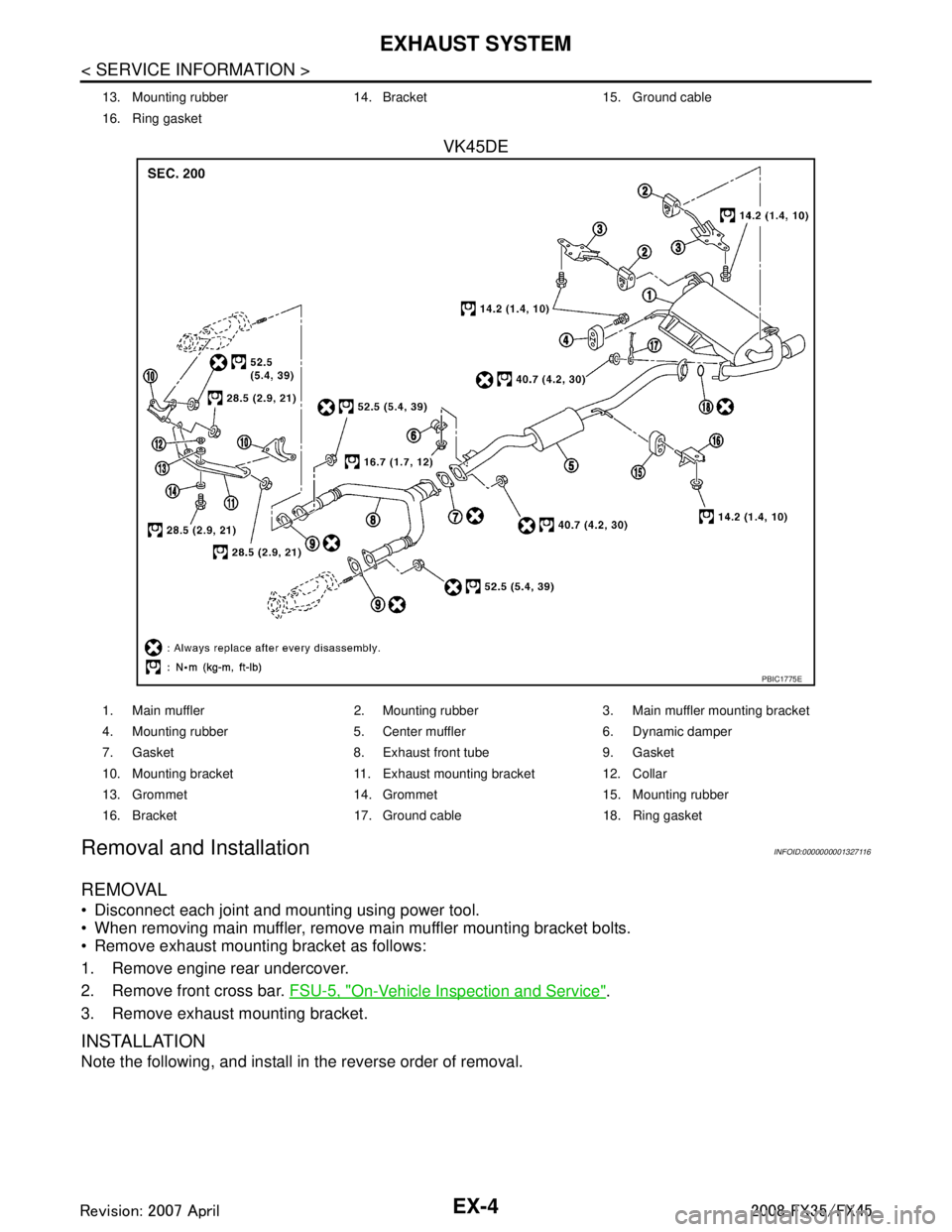
VK45DE
Removal and InstallationINFOID:0000000001327116
REMOVAL
Disconnect each joint and mounting using power tool.
When removing main muffler, remove main muffler mounting bracket bolts.
Remove exhaust mounting bracket as follows:
1. Remove engine rear undercover.
2. Remove front cross bar. FSU-5, "
On-Vehicle Inspection and Service".
3. Remove exhaust mounting bracket.
INSTALLATION
Note the following, and install in the reverse order of removal.
13. Mounting rubber 14. Bracket 15. Ground cable
16. Ring gasket
PBIC1775E
1. Main muffler 2. Mounting rubber 3. Main muffler mounting bracket
4. Mounting rubber 5. Center muffler 6. Dynamic damper
7. Gasket 8. Exhaust front tube 9. Gasket
10. Mounting bracket 11. Exhaust mounting bracket 12. Collar
13. Grommet 14. Grommet 15. Mounting rubber
16. Bracket 17. Ground cable 18. Ring gasket
3AA93ABC3ACD3AC03ACA3AC03AC63AC53A913A773A893A873A873A8E3A773A983AC73AC93AC03AC3
3A893A873A873A8F3A773A9D3AAF3A8A3A8C3A863A9D3AAF3A8B3A8C
Page 2765 of 3924

EXHAUST SYSTEMEX-5
< SERVICE INFORMATION >
C
DE
F
G H
I
J
K L
M A
EX
NP
O
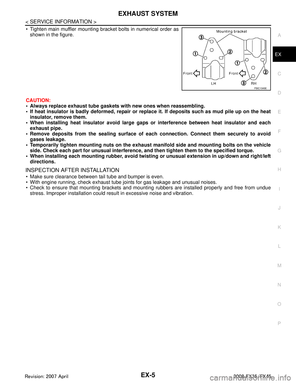
Tighten main muffler mounting bracket bolts in numerical order as
shown in the figure.
CAUTION:
Always replace exhaust tube gasket s with new ones when reassembling.
If heat insulator is badly deformed, repair or repl ace it. If deposits such as mud pile up on the heat
insulator, remove them.
When installing heat insulator avoid large gaps or interference between heat insulator and each
exhaust pipe.
Remove deposits from the sealing surface of each connection. Connect them securely to avoid
gases leakage.
Temporarily tighten mounting nuts on the exhaust manifold side and mounting bolts on the vehicle
side. Check each part for unusual interference, an d then tighten them to the specified torque.
When installing each mounting rubber, avoid twisting or unusual extension in up/down and right/left
directions.
INSPECTION AFTER INSTALLATION
Make sure clearance between tail tube and bumper is even.
With engine running, check exhaust tube joints for gas leakage and unusual noises.
Check to ensure that mounting brackets and mount ing rubbers are installed properly and free from undue
stress. Improper installation could resu lt in excessive noise and vibration.
PBIC1049E
3AA93ABC3ACD3AC03ACA3AC03AC63AC53A913A773A893A873A873A8E3A773A983AC73AC93AC03AC3
3A893A873A873A8F3A773A9D3AAF3A8A3A8C3A863A9D3AAF3A8B3A8C
Page 2766 of 3924

FAX-1
DRIVELINE/AXLE
CEF
G H
I
J
K L
M
SECTION FA X
A
B
FA X
N
O P
CONTENTS
FRONT AXLE
2WD
SERVICE INFORMATION .. ..........................
2
PREPARATION .............................................. .....2
Special Service Tool ........................................... ......2
Commercial Service Tool ..........................................2
NOISE, VIBRATION AND HARSHNESS
(NVH) TROUBLESHOOTING .............................
3
NVH Troubleshooting Chart ................................ ......3
FRONT WHEEL HUB AND KNUCKLE ..............4
On-Vehicle Inspection ......................................... ......4
Removal and Installation ...........................................4
SERVICE DATA AND SPECIFICATIONS
(SDS) ...................................................................
6
Wheel Bearing ..................................................... ......6
AWD
SERVICE INFORMATION .. ..........................
7
PRECAUTIONS .............................................. .....7
Caution ................................................................ ......7
PREPARATION ..................................................8
Special Service Tool ............................................ .....8
Commercial Service Tool .........................................9
NOISE, VIBRATION AND HARSHNESS
(NVH) TROUBLESHOOTING ...........................
10
NVH Troubleshooting Chart ....................................10
FRONT WHEEL HUB AND KNUCKLE ............11
On-Vehicle Inspection ......................................... ....11
Removal and Installation .........................................11
FRONT DRIVE SHAFT .....................................13
On-Vehicle Inspection .............................................13
Removal and Installation (Left Side) ........................15
Removal and Installation (Right Side) .....................16
Disassembly and Assembly (Left Side) ...................18
Disassembly and Assembly (Right Side) .................21
SERVICE DATA AND SPECIFICATIONS
(SDS) .................................................................
26
Wheel Bearing .........................................................26
Drive Shaft ...............................................................26
3AA93ABC3ACD3AC03ACA3AC03AC63AC53A913A773A893A873A873A8E3A773A983AC73AC93AC03AC3
3A893A873A873A8F3A773A9D3AAF3A8A3A8C3A863A9D3AAF3A8B3A8C
Page 2768 of 3924
![INFINITI FX35 2008 Service Manual
NOISE, VIBRATION AND HARSHNESS (NVH) TROUBLESHOOTINGFAX-3
< SERVICE INFORMATION > [2WD]
C
EF
G H
I
J
K L
M A
B
FA X
N
O P
NOISE, VIBRATION AND HARSHN ESS (NVH) TROUBLESHOOTING
NVH Troubleshooting Cha INFINITI FX35 2008 Service Manual
NOISE, VIBRATION AND HARSHNESS (NVH) TROUBLESHOOTINGFAX-3
< SERVICE INFORMATION > [2WD]
C
EF
G H
I
J
K L
M A
B
FA X
N
O P
NOISE, VIBRATION AND HARSHN ESS (NVH) TROUBLESHOOTING
NVH Troubleshooting Cha](/manual-img/42/57017/w960_57017-2767.png)
NOISE, VIBRATION AND HARSHNESS (NVH) TROUBLESHOOTINGFAX-3
< SERVICE INFORMATION > [2WD]
C
EF
G H
I
J
K L
M A
B
FA X
N
O P
NOISE, VIBRATION AND HARSHN ESS (NVH) TROUBLESHOOTING
NVH Troubleshooting ChartINFOID:0000000001327505
Use chart below to help you find the cause of the symp tom. If necessary, repair or replace these parts.
×: Applicable
Reference page
FAX-4—
FAX-4
NVH in WT section
NVH in WT section
NVH in PS section
Possible cause and SUSPECTED PARTS
Improper installation, looseness
Parts interference
Wheel bearing damage
TIRE
ROAD WHEEL
STEERING
Symptom FRONT AXLE Noise
×× ×××
Shake ×× ×××
Vibration ××××
Shimmy ×× ×××
Judder ××××
Poor quality ride or handling ×××××
3AA93ABC3ACD3AC03ACA3AC03AC63AC53A913A773A893A873A873A8E3A773A983AC73AC93AC03AC3
3A893A873A873A8F3A773A9D3AAF3A8A3A8C3A863A9D3AAF3A8B3A8C