2008 INFINITI FX35 tire type
[x] Cancel search: tire typePage 3 of 3924

QUICK REFERENCE CHART FX35/FX45
ENGINE TUNE-UP DATA (VK45DE)
FRONT WHEEL ALIGNMENT (Unladen* )
ELS0003X
* : Fuel, engine coolant and engine oil full. Spare tire, jack, hand tools and mats in designated positions.Engine modelVK45DE
Firing order1-8-7-3-6-5-4-2
Idle speed
A/T (In “P” or “N” position) rpm650 ± 50
Ignition timing (BTDC at idle speed)
A/T (In “P” or “N” position)12° ± 5°
Tensions of drive belts Auto adjustment by auto tensioner
Radiater cap relief pressure
kPa (kg/cm
2 , psi)
78 - 98 (0.8-1.0 , 11-14) Standard
Limit 59 (0.6, 9)
Cooling system leakage testing pressure
157 (1.6, 23)
kPa (kg/cm
2 , psi)
Compression pressure
kPa (kg/cm
2 , psi)/rpm
1,320 (13.5, 191) /300 Standard
Minimum 1,130 (11.5, 164) /300
Spark plug Standard type PLFR5A-11
Hot type PLFR4A-11
Cold type PLFR6A-11
Camber Degree minute (Decimal degree) Minimum –1° 29′ (–1.48°)
Nominal –0° 44′ (–0.73°)
Maximum 0° 01′ (0.02°)
Left and right difference 45′ (0.75°) or less
Caster Degree minute (Decimal degree) Minimum 3° 02′ (3.03°)
Nominal 3° 47′ (3.78°)
Maximum 4° 32′ (4.53°)
Left and right difference 45′ (0.75°) or less
Kingpin inclination Degree minute (Decimal degree) Minimum 12° 20′ (12.33°)
Nominal 13° 05′ (13.08°)
Maximum 13° 50′ (13.83°)
Total toe-in Distance Minimum 0.6 mm (0.024 in)
Nominal 1.6 mm (0.063 in)
Maximum 2.6 mm (0.102 in)
Angle (left wheel or right wheel)
Degree minute (Decimal degree)Minimum 0° 01′ (0.02°)
Nominal 0° 04′ (0.06°)
Maximum 0° 06′ (0.10°)
Wheel turning angle (Full turn) Inside Minimum 32° 00 (32.0°)
Degree minute (Decimal degree) Nominal 35° 00 (35.0°)
Maximum 36° 00 (36.0°)
Outside
Nominal 30° 00 (30.0°)
Degree minute (Decimal degree)
2008
Page 635 of 3924

AV-88
< SERVICE INFORMATION >
NAVIGATION SYSTEM
The navigation system periodically calculates the vehicle's current
position according to the following three signals:
Travel distance of the vehicle as determined by the vehicle speed sensor
Turning angle of the vehicle as determined by the gyroscope (angular velocity sensor)
Direction of vehicle travel as determined by the GPS antenna (GPS information)
The current position of the vehicle is then identified by comparing the
calculated vehicle position with map data read from the DVD-ROM,
which is stored in the DVD-ROM drive (map-matching), and indi-
cated on the screen as a current-loc ation mark. More accurate data
is judged and used by comparing vehicle position detecti on results found by the GPS with the result by map-
matching.
The current vehicle position will be calculated by detecting the dis-
tance the vehicle moved from the previous calculation point and its
direction.
Travel distance Travel distance calculations are based on the vehicle speed sen-
sor input signal. Therefore, the calculation may become incorrect
as the tires wear down. To prevent this, an automatic distance cor-
rection function has been adopted.
Travel direction Change in the travel direction of the vehicle is calculated by a gyro-
scope (angular velocity sensor) and a GPS antenna (GPS informa-
tion). They have both advantages and disadvantages.
More accurate traveling direction is selected because pr iorities are set for the signals from these two devices
according to the situation.
Map-Matching
Map-matching compares a current location detected by the method
in the “Location Detection Principle” with a road map data from DVD-
ROM stored in DVD-ROM drive.
NOTE:
The road map data is based on data stored in the DVD-ROM.
The vehicle position may not be corrected under the following circumstances and after driving for a certain
time when GPS information is difficult to receive. In th is case, the current-location mark on the display must be
corrected manually.
SKIB1058E
SEL684V
Type Advantage Disadvantage
Gyroscope (angular velocity sen-
sor) Can detect the vehicle's turning angle quite
accurately. Direction errors
may accumulate when vehicle is
driven for long distances without stopping.
GPS antenna (GPS information) Can detect the vehicle's travel direction
(North/South/East/West). Correct direction cannot be detected when vehicle
speed is low.
SEL685V
3AA93ABC3ACD3AC03ACA3AC03AC63AC53A913A773A893A873A873A8E3A773A983AC73AC93AC03AC3
3A893A873A873A8F3A773A9D3AAF3A8A3A8C3A863A9D3AAF3A8B3A8C
Page 1020 of 3924
![INFINITI FX35 2008 Service Manual
PRECAUTIONSBRC-5
< SERVICE INFORMATION > [VDC/TCS/ABS]
C
D
E
G H
I
J
K L
M A
B
BRC
N
O P
PRECAUTIONS
Precaution for Supplemental Restraint System (SRS) "AIR BAG" and "SEAT BELT
PRE-TENSIONER"
INFOI INFINITI FX35 2008 Service Manual
PRECAUTIONSBRC-5
< SERVICE INFORMATION > [VDC/TCS/ABS]
C
D
E
G H
I
J
K L
M A
B
BRC
N
O P
PRECAUTIONS
Precaution for Supplemental Restraint System (SRS) "AIR BAG" and "SEAT BELT
PRE-TENSIONER"
INFOI](/manual-img/42/57017/w960_57017-1019.png)
PRECAUTIONSBRC-5
< SERVICE INFORMATION > [VDC/TCS/ABS]
C
D
E
G H
I
J
K L
M A
B
BRC
N
O P
PRECAUTIONS
Precaution for Supplemental Restraint System (SRS) "AIR BAG" and "SEAT BELT
PRE-TENSIONER"
INFOID:0000000001612923
The Supplemental Restraint System such as “A IR BAG” and “SEAT BELT PRE-TENSIONER”, used along
with a front seat belt, helps to reduce the risk or severi ty of injury to the driver and front passenger for certain
types of collision. This system includes seat belt switch inputs and dual stage front air bag modules. The SRS
system uses the seat belt switches to determine the front air bag deployment, and may only deploy one front
air bag, depending on the severity of a collision and whether the front occupants are belted or unbelted.
Information necessary to service the system safely is included in the “SUPPLEMENTAL RESTRAINT SYS-
TEM” and “SEAT BELTS” of this Service Manual.
WARNING:
• To avoid rendering the SRS inoper ative, which could increase the risk of personal injury or death in
the event of a collision which would result in air bag inflation, all maintenance must be performed by
an authorized NISSAN/INFINITI dealer.
Improper maintenance, including in correct removal and installation of the SRS, can lead to personal
injury caused by unintentional act ivation of the system. For removal of Spiral Cable and Air Bag
Module, see the “SUPPLEMEN TAL RESTRAINT SYSTEM”.
Do not use electrical test equipm ent on any circuit related to the SRS unless instructed to in this
Service Manual. SRS wiring harnesses can be identi fied by yellow and/or orange harnesses or har-
ness connectors.
Precaution for Brake SystemINFOID:0000000001327654
Recommended fluid is brake fluid “DOT 3”. Refer to MA-9.
Do not reuse drained brake fluid.
Be careful not to splash brake fluid on painted areas such as body. If brake fluid is splashed, wipe it off and flush area with water immediately.
Do not use mineral oils such as gasoline or kerosene to clean. They will ruin rubber parts and cause improper operation.
Using a flare nut crowfoot and torque wrench, securely tighten brake tube flare nuts.
Brake system is an important safe ty part. If a brake fluid leak is
detected, always disassemble the affected part. If a malfunction is
detected, replace part with a new one.
Before working, turn ignition switch OFF and disconnect electrical
connectors of ABS actuator and elec tric unit (control unit) or bat-
tery negative terminal.
When installing brake piping, be sure to check torque.
WARNING:
Clean brake pads and shoes with a waste cloth, then wipe with
a dust collector.
Precaution for Brake ControlINFOID:0000000001327655
During VDC/TCS/ABS operation, brake pedal lightly vi brates and a mechanical noise may be heard. This is
normal.
Just after starting vehicle after turning ignition switch ON, brake pedal may vibrate or motor operating noise
may be heard from engine room. This is a normal status of operation check.
Stopping distance may be longer than that of vehicles without ABS when vehicle drives on rough, gravel, or
snow-covered (fresh, deep snow) roads.
When an error is indicated by ABS or another warning lamp, collect all necessary information from customer
(what symptoms are present under what conditions) and check for simple causes before starting diagnostic
servicing. Besides electrical system inspection, c heck booster operation, brake fluid level, and fluid leaks.
If tire size and type are used in an improper combinat ion, or brake pads are not Genuine NISSAN parts,
stopping distance or steering stability may deteriorate.
If there is a radio, antenna, or antenna lead-in wire (including wiring) near control module, VDC/TCS/ABS
function may have a malfunction or error.
If aftermarket parts (car stereo, CD player, etc.) have been installed, check for incidents such as harness
pinches, open circuits, and improper wiring.
SBR686C
3AA93ABC3ACD3AC03ACA3AC03AC63AC53A913A773A893A873A873A8E3A773A983AC73AC93AC03AC3
3A893A873A873A8F3A773A9D3AAF3A8A3A8C3A863A9D3AAF3A8B3A8C
Page 2483 of 3924

EI-46
< SERVICE INFORMATION >
LUGGAGE FLOOR TRIM
Removal and Installation
INFOID:0000000001529413
REMOVAL
1. Remove tonneau cover.
2. Remove luggage side hook and remove net hook (RH/LH).
3. Remove luggage floor board assembly. Remove bolt with power tool.
4. Remove luggage floor side board assembly (RH/LH).
5. Remove back door weather strip.
6. Remove rear plate assembly.
7. Remove roof rear garnish assembly.
8. Remove luggage floor cover assembly (RH/LH).
9. Remove rear door kicking plate (RH/LH).
10. Remove rear body side welt.
11. Remove rear seat cushion and seatback. Refer to SE-95, "
Removal and Installation".
12. Remove rear wheel house finisher assembly (RH/LH).
13. Remove luggage side finisher assembly bolt and remove luggage side finisher assembly (RH/LH).
14. Remove bolt, and then remove parcel shelf holder.
15. Remove rear parcel shelf cap.
16. Remove bolt, and then remove rear parcel hook.
17. Remove rear seat belt anchor (RH/LH). Refer to SB-5, "
Removal and Installation of Rear Seat Belt".
18. Remove rear pillar upper garnish assembly cap and bolt, then remove rear pillar upper garnish assembly (RH/LH).
19. Remove spare tire clamp.
20. Remove sub-woofer box connector and remove sub-woofer box.
21. Remove spare tire.
22. Remove towing hook, wheel nut wrench, spanner, tire stopper, jack rod and jack complete.
23. Remove luggage side box bolt and luggage side box assembly (RH/LH).
INSTALLATION
Install in the reverse order of removal.
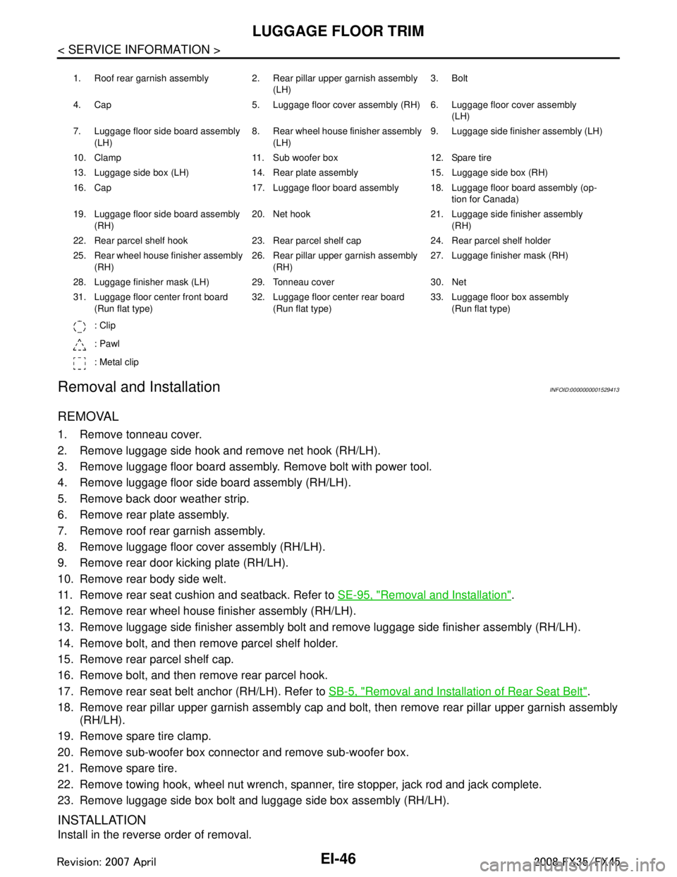
1. Roof rear garnish assembly 2. Rear pillar upper garnish assembly (LH)3. Bolt
4. Cap 5. Luggage floor cover assembly (RH) 6. Luggage floor cover assembly (LH)
7. Luggage floor side board assembly (LH) 8. Rear wheel house finisher assembly
(LH) 9. Luggage side finisher assembly (LH)
10. Clamp 11. Sub woofer box 12. Spare tire
13. Luggage side box (LH) 14. Rear plate assembly 15. Luggage side box (RH)
16. Cap 17. Luggage floor board assembly 18. Luggage floor board assembly (op- tion for Canada)
19. Luggage floor side board assembly (RH) 20. Net hook 21. Luggage side finisher assembly
(RH)
22. Rear parcel shelf hook 23. Rear parcel shelf cap 24. Rear parcel shelf holder
25. Rear wheel house finisher assembly (RH) 26. Rear pillar upper garnish assembly
(RH) 27. Luggage finisher mask (RH)
28. Luggage finisher mask (LH) 29. Tonneau cover 30. Net
31. Luggage floor center front board (Run flat type) 32. Luggage floor center rear board
(Run flat type) 33. Luggage floor box assembly
(Run flat type)
: Clip
: Pawl
: Metal clip
3AA93ABC3ACD3AC03ACA3AC03AC63AC53A913A773A893A873A873A8E3A773A983AC73AC93AC03AC3
3A893A873A873A8F3A773A9D3AAF3A8A3A8C3A863A9D3AAF3A8B3A8C
Page 2849 of 3924

FRONT SUSPENSION ASSEMBLYFSU-5
< SERVICE INFORMATION >
C
DF
G H
I
J
K L
M A
B
FSU
N
O P
FRONT SUSPENSION ASSEMBLY
On-Vehicle Inspection and ServiceINFOID:0000000001327537
Make sure the mounting conditions (looseness, back lash) of each component and component conditions
(wear, damage) are normal.
INSPECTION LOWER BALL JOINT END PLAY
1. Set front wheels in a straight-ahead position. Do not depress brake pedal.
2. Place an iron bar or similar tool bet ween transverse link and steering knuckle.
3. Measure axial end play by prying it up and down.
CAUTION:
Be careful not to damage ball joint boot.
STRUT INSPECTION
Check strut for oil leakage, damage and replace if there are. Refer to FSU-10.
Wheel Alignment InspectionINFOID:0000000001327538
DESCRIPTION
Measure wheel alignment under unladen conditions.
NOTE:
Unladen conditions mean that fuel, engine coolant, and l ubricant are full. Spare tire, jack, hand tools and
mats are designated positions.
PRELIMINARY CHECK
Check tires for improper air pressure and wear.
Check road wheels for runout.
Check wheel bearing axial end play.
Check ball joint axial end play of compression rod, upper link, and steering knuckle
Check shock absorber operation.
Check each mounting part of axle and suspension for looseness and deformation.
Check each link, rod and member for cracks, deformation and other damage.
Check vehicle posture.
GENERAL INFORMATION AND RECOMMENDATIONS
A four-wheel thrust alignment should be performed.
- This type of alignment is recomm ended for any NISSAN/INFINITI vehicle.
- The four-wheel “thrust” process helps ensure that t he vehicle is properly aligned and the steering wheel is
centered.
- The alignment rack itself should be capable of accepting any NISSAN/INFINITI vehicle.
- The rack should be checked to ensure that it is level.
Make sure the machine is properly calibrated.
- Your alignment equipment should be regularly ca librated in order to give correct information.
- Check with the manufacturer of your specific equi pment for their recommended Service/Calibration Sched-
ule.
THE ALIGNMENT PROCESS
IMPORTANT:
Use only the alignment specificati ons listed in this Service Manual.
When displaying the alignment settings, many alignment machines use “indicators”: (Green/red, plus or
minus, Go/No Go). Do NOT use these indicators.
- The alignment specifications programmed into your machine that operate these indicators may not be cor-
rect.
- This may result in an ERROR.
Some newer alignment machines are equipped with an optional “Rolling Compensation” method to “com-
pensate” the sensors (alignment targets or head units). DO NOT use this “Rolling Compensation”
method. Axial end play : 0 mm (0 in)
3AA93ABC3ACD3AC03ACA3AC03AC63AC53A913A773A893A873A873A8E3A773A983AC73AC93AC03AC3
3A893A873A873A8F3A773A9D3AAF3A8A3A8C3A863A9D3AAF3A8B3A8C
Page 2859 of 3924

STABILIZER BARFSU-15
< SERVICE INFORMATION >
C
DF
G H
I
J
K L
M A
B
FSU
N
O P
STABILIZER BAR
Removal and InstallationINFOID:0000000001327543
REMOVAL
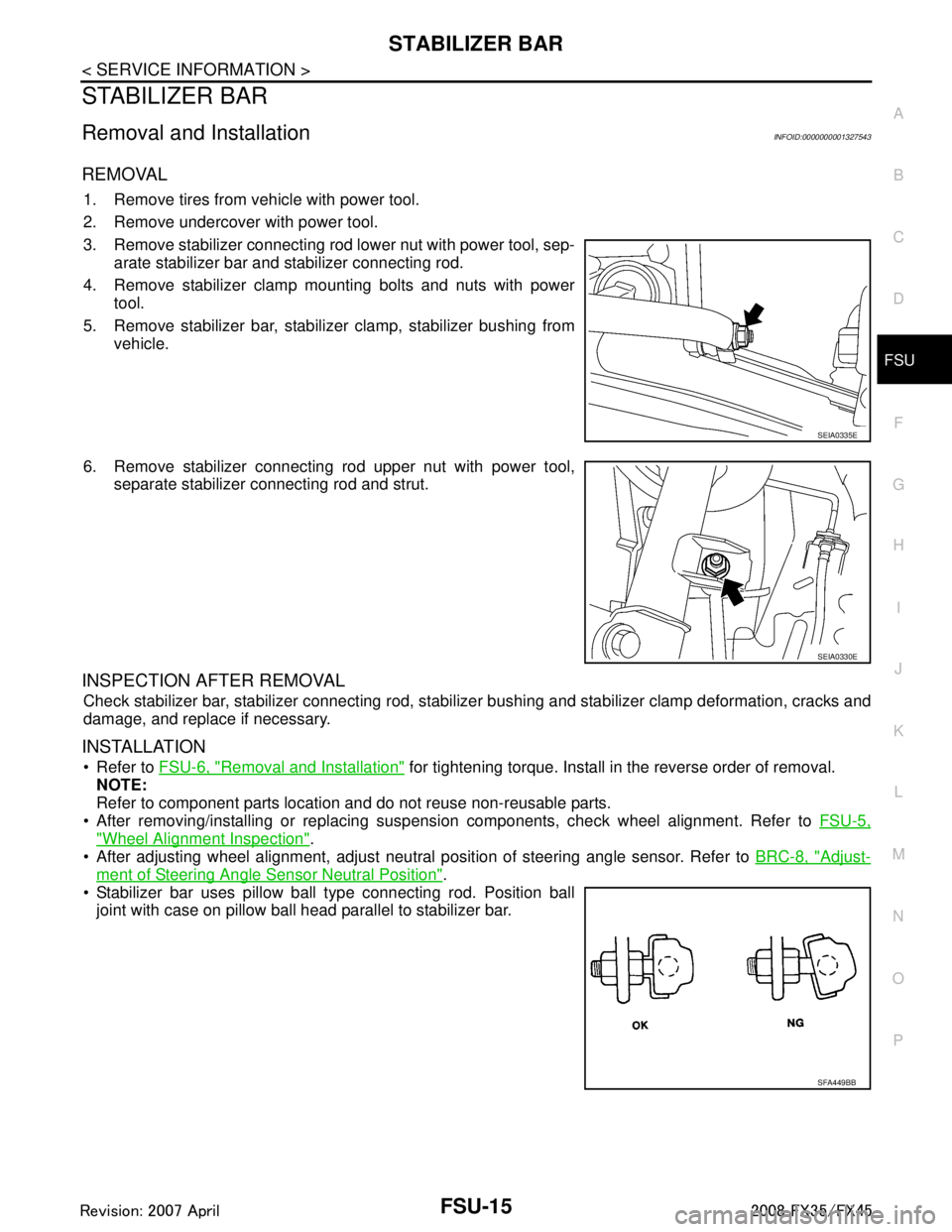
1. Remove tires from vehicle with power tool.
2. Remove undercover with power tool.
3. Remove stabilizer connecting rod lower nut with power tool, sep- arate stabilizer bar and stabilizer connecting rod.
4. Remove stabilizer clamp mounting bolts and nuts with power tool.
5. Remove stabilizer bar, stabilizer clamp, stabilizer bushing from vehicle.
6. Remove stabilizer connecting rod upper nut with power tool, separate stabilizer connecting rod and strut.
INSPECTION AFTER REMOVAL
Check stabilizer bar, stabilizer connecting rod, stabiliz er bushing and stabilizer clamp deformation, cracks and
damage, and replace if necessary.
INSTALLATION
Refer to FSU-6, "Removal and Installation" for tightening torque. Install in the reverse order of removal.
NOTE:
Refer to component parts location and do not reuse non-reusable parts.
After removing/installing or replacing suspension components, check wheel alignment. Refer to FSU-5,
"Wheel Alignment Inspection".
After adjusting wheel alignment, adjust neutral position of steering angle sensor. Refer to BRC-8, "
Adjust-
ment of Steering Angle Sensor Neutral Position".
Stabilizer bar uses pillow ball type connecting rod. Position ball
joint with case on pillow ball head parallel to stabilizer bar.
SEIA0335E
SEIA0330E
SFA449BB
3AA93ABC3ACD3AC03ACA3AC03AC63AC53A913A773A893A873A873A8E3A773A983AC73AC93AC03AC3
3A893A873A873A8F3A773A9D3AAF3A8A3A8C3A863A9D3AAF3A8B3A8C
Page 3129 of 3924

HEADLAMP - XENON TYPE -LT-27
< SERVICE INFORMATION >
C
DE
F
G H
I
J
L
M A
B
LT
N
O P
Xenon Headlamp Trouble DiagnosisINFOID:0000000001328286
1.CHECK 1: XENON HEADLAMP LIGHTING
Install normal xenon bulb to corresponding xenon bulb headlamp, and check if lamp lights up.
OK or NG
OK >> Replace xenon bulb.
NG >> GO TO 2.
2.CHECK 2: XENON HEADLAMP LIGHTING
Install normal HID control unit to corresponding xenon headlamp, and check if lamp lights up.
OK or NG
OK >> Replace HID control unit.
NG >> GO TO 3.
3.CHECK 3: XENON HEADLAMP LIGHTING
Install normal xenon lamp housing assembly to corresponding xenon headlamp, and check if lamp lights up.
OK or NG
OK >> Replace xenon headlamp housing assembly. [Malfunction in starter (boosting circuit) in xenon headlamp housing]
NG >> INSPECTION END
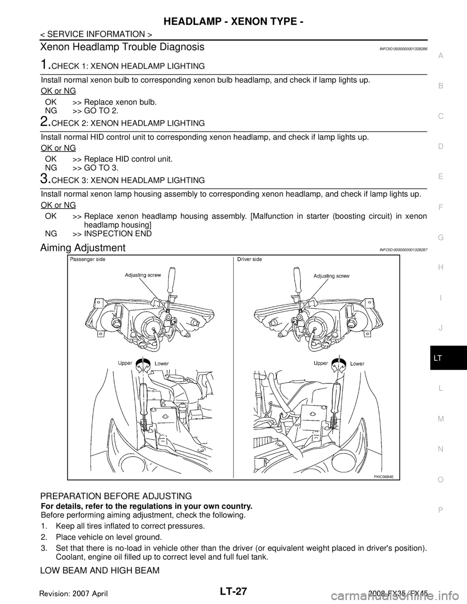
Aiming AdjustmentINFOID:0000000001328287
PREPARATION BEFORE ADJUSTING
For details, refer to the regulations in your own country.
Before performing aiming adjustment, check the following.
1. Keep all tires inflated to correct pressures.
2. Place vehicle on level ground.
3. Set that there is no-load in vehicle other than the driv er (or equivalent weight placed in driver's position).
Coolant, engine oil filled up to correct level and full fuel tank.
LOW BEAM AND HIGH BEAM
PKIC9684E
3AA93ABC3ACD3AC03ACA3AC03AC63AC53A913A773A893A873A873A8E3A773A983AC73AC93AC03AC3
3A893A873A873A8F3A773A9D3AAF3A8A3A8C3A863A9D3AAF3A8B3A8C
Page 3177 of 3924

FRONT FOG LAMPLT-75
< SERVICE INFORMATION >
C
DE
F
G H
I
J
L
M A
B
LT
N
O P
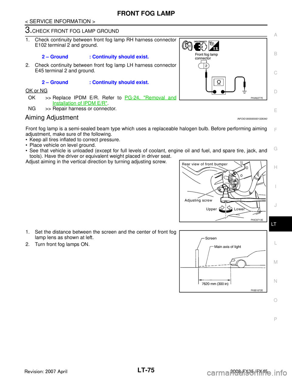
3.CHECK FRONT FOG LAMP GROUND
1. Check continuity between front fog lamp RH harness connector E102 terminal 2 and ground.
2. Check continuity between front fog lamp LH harness connector E45 terminal 2 and ground.
OK or NG
OK >> Replace IPDM E/R. Refer to PG-24, "Removal and
Installation of IPDM E/R".
NG >> Repair harness or connector.
Aiming AdjustmentINFOID:0000000001328340
Front fog lamp is a semi-sealed beam type which uses a replaceable halogen bulb. Before performing aiming
adjustment, make sure of the following.
Keep all tires inflated to correct pressure.
Place vehicle on level ground.
See that vehicle is unloaded (except for full levels of coolant, engine oil and fuel, and spare tire, jack, and tools). Have the driver or equivalent weight placed in driver seat.
Adjust aiming in the vertical direction by turning adjusting screw.
1. Set the distance between the scr een and the center of front fog
lamp lens as shown at left.
2. Turn front fog lamps ON. 2 – Ground : Continuity should exist.
2 – Ground : Continuity should exist.
PKIA6277E
PKIC9713E
PKIB1672E
3AA93ABC3ACD3AC03ACA3AC03AC63AC53A913A773A893A873A873A8E3A773A983AC73AC93AC03AC3
3A893A873A873A8F3A773A9D3AAF3A8A3A8C3A863A9D3AAF3A8B3A8C