2008 INFINITI FX35 b2202
[x] Cancel search: b2202Page 1127 of 3924

DI-1
ELECTRICAL
C
DE
F
G H
I
J
L
M
SECTION DI
A
B
DI
N
O P
CONTENTS
DRIVER INFORMATION SYSTEM
SERVICE INFORMATION .. ..........................3
DTC INDEX ..................................................... .....3
U1000 - U1010 .................................................... ......3
B2202 - B2205 ..........................................................3
C1B00 - C1B03 .........................................................3
PRECAUTION .....................................................4
Precaution for Supplemental Restraint System
(SRS) "AIR BAG" and "SEAT BELT PRE-TEN-
SIONER" ............................................................. ......
4
COMBINATION METERS ...................................5
System Description ............................................. ......5
Component Parts and Harness Connector Loca-
tion ............................................................................
8
Arrangement of Combination Meter ..........................9
Circuit Diagram .......................................................10
Wiring Diagram - METER - .....................................11
Terminal and Reference Value for Combination
Meter .......................................................................
13
Terminal and Reference Value for Unified Meter
and A/C Amp ...........................................................
14
Self-Diagnosis Mode of Combination Meter ............14
CONSULT-III Function (METER/M&A) ...................15
Trouble Diagnosis ...................................................15
Symptom Chart .......................................................16
Power Supply and Ground Circuit Inspection .........16
Vehicle Speed Signal Inspection .............................17
Engine Speed Signal Inspection .............................18
Engine Coolant Temperature Signal Inspection ......19
Fuel Level Sensor Signal Inspection .......................19
Fuel Gauge Pointer Fluctuates, Indicator Wrong
Value or Varies ........................................................
21
Fuel Gauge Does Not Move to FULL Position ........21
Odo/Trip Meter and Illumination Control Switch In-
spection ............................................................... ....
21
Electrical Component Inspection .............................21
Removal and Installation of Combination Meter .....22
Disassembly and Assembly of Combination Meter
....
23
Removal and Installation of Odo/Trip Meter and Il-
lumination Control Switch .................................... ....
24
UNIFIED METER AND A/C AMP ......................26
System Description ..................................................26
Schematic ................................................................27
CONSULT-III Function (METER/M&A) ....................27
Power Supply and Ground Circuit Inspection ..........29
DTC [U1000] CAN Communication Circuit ..............30
DTC [B2202] Meter Commun ication Circuit ............30
DTC [B2205] Vehicle Speed Circuit .................... ....32
Removal and Installation of Unified Meter and A/C
Amp .........................................................................
32
WARNING LAMPS ............................................34
System Description .............................................. ....34
Schematic ................................................................35
Wiring Diagram - WARN - .......................................36
Oil Pressure Warning Lamp Stays Off (Ignition
Switch ON) .......................................................... ....
43
Oil Pressure Warning Lamp Does Not Turn Off
(Oil Pressure Is Normal) ...................................... ....
45
Component Inspection .............................................46
A/T INDICATOR ................................................47
System Description ..................................................47
Wiring Diagram - AT/IND - .......................................48
A/T Indicator Is Malfunction .....................................49
WARNING CHIME .............................................51
System Description .............................................. ....51
Component Parts and Harness Connector Loca-
tion ...........................................................................
53
Schematic ................................................................54
Wiring Diagram - CHIME - .......................................55
Terminal and Reference Value for BCM ..................57
Terminal and Reference Value for Unified Meter
and A/C Amp. ...................................................... ....
59
Terminal and Reference Value for Combination
Meter .......................................................................
59
CONSULT-III Function (METER/M&A) ....................60
3AA93ABC3ACD3AC03ACA3AC03AC63AC53A913A773A893A873A873A8E3A773A983AC73AC93AC03AC3
3A893A873A873A8F3A773A9D3AAF3A8A3A8C3A863A9D3AAF3A8B3A8C
Page 1129 of 3924

DTC INDEXDI-3
< SERVICE INFORMATION >
C
DE
F
G H
I
J
L
M A
B
DI
N
O P
SERVICE INFORMATION
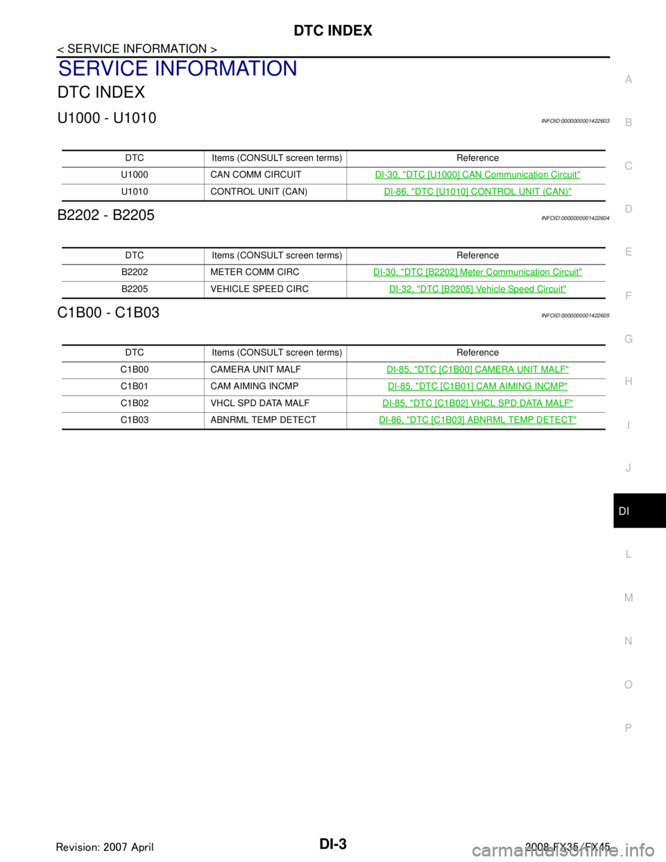
DTC INDEX
U1000 - U1010INFOID:0000000001422603
B2202 - B2205INFOID:0000000001422604
C1B00 - C1B03INFOID:0000000001422605
DTC Items (CONSULT sc reen terms) Reference
U1000 CAN COMM CIRCUIT DI-30, "
DTC [U1000] CAN Communication Circuit"
U1010 CONTROL UNIT (CAN) DI-86, "DTC [U1010] CONTROL UNIT (CAN)"
DTC Items (CONSULT screen terms) Reference
B2202 METER COMM CIRC DI-30, "
DTC [B2202] Meter Communication Circuit"
B2205 VEHICLE SPEED CIRC DI-32, "DTC [B2205] Vehicle Speed Circuit"
DTC Items (CONSULT screen terms) Reference
C1B00 CAMERA UNIT MALF DI-85, "
DTC [C1B00] CAMERA UNIT MALF"
C1B01 CAM AIMING INCMP DI-85, "DTC [C1B01] CAM AIMING INCMP"
C1B02 VHCL SPD DATA MALFDI-85, "DTC [C1B02] VHCL SPD DATA MALF"
C1B03 ABNRML TEMP DETECTDI-86, "DTC [C1B03] ABNRML TEMP DETECT"
3AA93ABC3ACD3AC03ACA3AC03AC63AC53A913A773A893A873A873A8E3A773A983AC73AC93AC03AC3
3A893A873A873A8F3A773A9D3AAF3A8A3A8C3A863A9D3AAF3A8B3A8C
Page 1154 of 3924

DI-28
< SERVICE INFORMATION >
UNIFIED METER AND A/C AMP
SELF-DIAG RESULTS
Display Item List
NOTE:
“TIME” means the following.
0: Means detected malfunction at present. (From malfunction detection to turning ignition switch OFF)
1 - 63: Means detected malfunction in the past . (Displays the number of ignition switch OFF → ON after
detecting malfunction. “Self Diagnostic Result” is erased when exceeding “63”.)
DATA MONITOR
Display Item List
X: Applicable
System Diagnosis mode Description
METER A/C AMP Self Diagnostic Result
Unified meter and A/C amp. checks the conditions and displays
memorized error.
CAN DIAG SUPPORT MNTR The results of transmit/receive diagnosis of CAN communication
can be read.
Data Monitor Displays unified meter and A/C amp. input data in real time.
Display item [Code] Malfunction is detected when... Reference
page
CAN COMM CIRC [U1000] When unified meter and A/C amp. is not transmitting or receiving CAN communication
signal for 2 seconds or more. DI-30
METER COMM CIRC [B2202]Malfunction is detected in communication of between combination meter and unified
meter and A/C amp.
DI-30
VEHICLE SPEED CIRC [B2205]When an erroneous speed signal is input for 1 second.
NOTE:
Even when there is no malfunction on speed signal system, malfunction may be misin-
terpreted when battery has low voltage (when maintaining 7 - 8 V for about 2 seconds). DI-32
Display item [Unit]
MAIN
SIGNALS SELECTION
FROM MENU Contents
SPEED METER [km/h] or [mph] X X Displays the value of vehicle speed signal, which is input from
ABS actuator and electric unit (control unit).
SPEED OUTPUT [km/h] or [mph] X X Displays the value of vehicle speed signal, which is transmitted
to each unit with CAN communication.
TACHO METER [rpm] X X Displays the value of engine speed signal, which is input from
ECM.
W TEMP METER [ °C] or [ °F] X X Displays the value of engine coolant temperature signal, which is
input from ECM.
FUEL METER [lit.] X X Displays the value, which processes a resistance signal from fuel
gauge.
DISTANCE [km] or [mile] X X Displays the value, which is calculated by vehicle speed signal
from ABS actuator and electric unit
(control unit), fuel gauge and
fuel consumption from ECM.
FUEL W/L [On/Off] X X Indicates [On/Off] condition of low-fuel warning lamp.
MIL [On/Off] X Indicates [On/Off] condition of malfunction indicator lamp.
AIR PRES W/L [On/Off] X Indicates [On/Off] condition of low tire pressure warning lamp.
SEAT BELT W/L [On/Off]
*1X Indicates [On/Off] condition of seat belt warning lamp.
BUZZER [On/Off] X X Indicates [On/Off] condition of buzzer.
DOOR W/L [On/Off] X Indicates [On/Off] condition of door warning lamp.
HI-BEAM IND [On/Off] X Indicates [On/Off] condition of high beam indicator.
TURN IND [On/Off] X Indicates [On/Off] condition of turn indicator.
3AA93ABC3ACD3AC03ACA3AC03AC63AC53A913A773A893A873A873A8E3A773A983AC73AC93AC03AC3
3A893A873A873A8F3A773A9D3AAF3A8A3A8C3A863A9D3AAF3A8B3A8C
Page 1156 of 3924

DI-30
< SERVICE INFORMATION >
UNIFIED METER AND A/C AMP
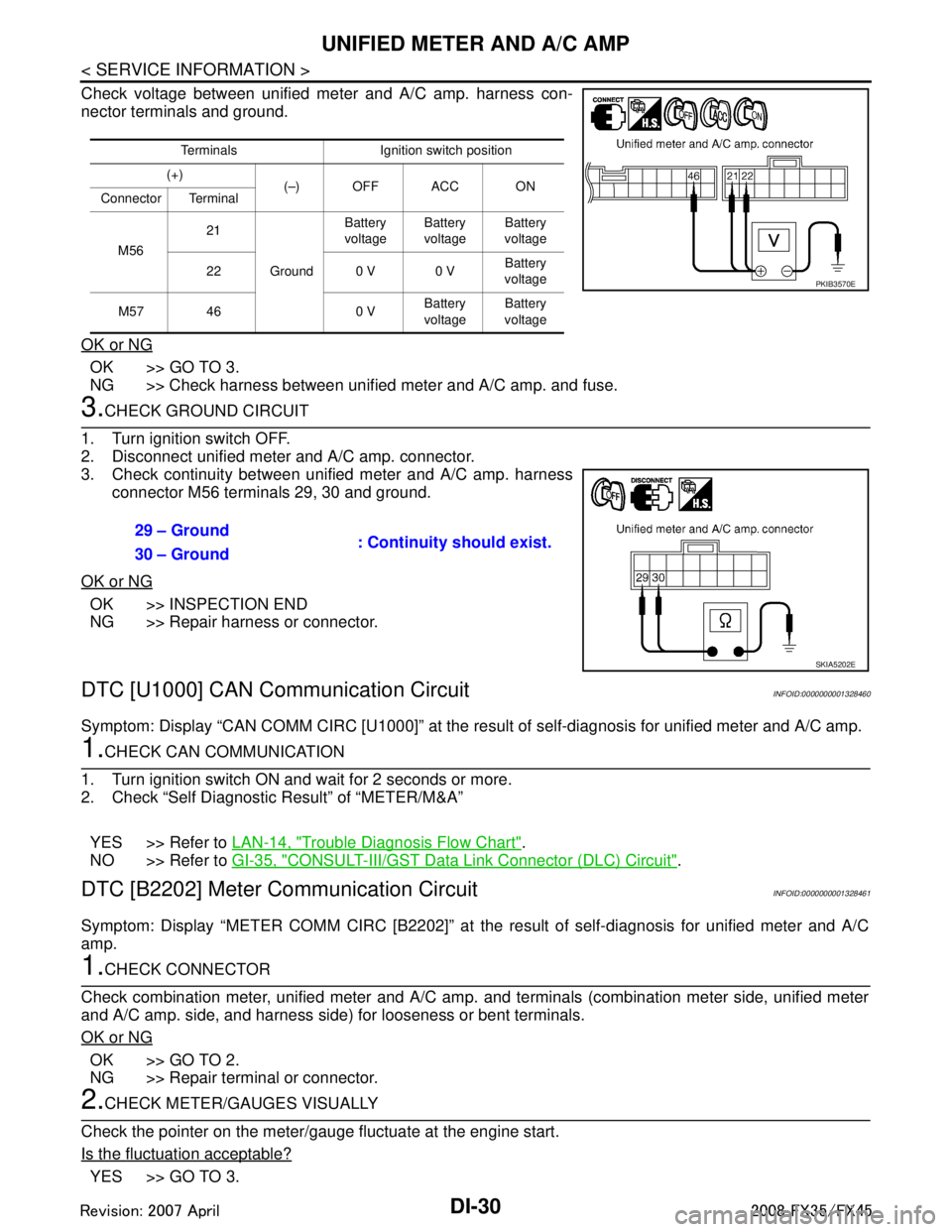
Check voltage between unified meter and A/C amp. harness con-
nector terminals and ground.
OK or NG
OK >> GO TO 3.
NG >> Check harness between unified meter and A/C amp. and fuse.
3.CHECK GROUND CIRCUIT
1. Turn ignition switch OFF.
2. Disconnect unified meter and A/C amp. connector.
3. Check continuity between unified meter and A/C amp. harness connector M56 terminals 29, 30 and ground.
OK or NG
OK >> INSPECTION END
NG >> Repair harness or connector.
DTC [U1000] CAN Communication CircuitINFOID:0000000001328460
Symptom: Display “CAN COMM CIRC [U1000]” at the re sult of self-diagnosis for unified meter and A/C amp.
1.CHECK CAN COMMUNICATION
1. Turn ignition switch ON and wait for 2 seconds or more.
2. Check “Self Diagnostic Result” of “METER/M&A”
YES >> Refer to LAN-14, "
Trouble Diagnosis Flow Chart".
NO >> Refer to GI-35, "
CONSULT-III/GST Data Link Connector (DLC) Circuit".
DTC [B2202] Meter Communication CircuitINFOID:0000000001328461
Symptom: Display “METER COMM CI RC [B2202]” at the result of self-diagnosis for unified meter and A/C
amp.
1.CHECK CONNECTOR
Check combination meter, unified meter and A/C amp. and terminals (combination meter side, unified meter
and A/C amp. side, and harness side) for looseness or bent terminals.
OK or NG
OK >> GO TO 2.
NG >> Repair terminal or connector.
2.CHECK METER/GAUGES VISUALLY
Check the pointer on the meter/gauge fluctuate at the engine start.
Is the fluctuation acceptable?
YES >> GO TO 3.
Terminals Ignition switch position
(+) (–) OFF ACC ON
Connector Terminal
M56 21
Ground Battery
voltage Battery
voltage Battery
voltage
22 0 V 0 V Battery
voltage
M57 46 0 V Battery
voltage Battery
voltage
PKIB3570E
29 – Ground : Continuity should exist.
30 – Ground
SKIA5202E
3AA93ABC3ACD3AC03ACA3AC03AC63AC53A913A773A893A873A873A8E3A773A983AC73AC93AC03AC3
3A893A873A873A8F3A773A9D3AAF3A8A3A8C3A863A9D3AAF3A8B3A8C
Page 1789 of 3924
![INFINITI FX35 2008 Service Manual
ASCD INDICATOREC-549
< SERVICE INFORMATION > [VQ35DE]
C
D
E
F
G H
I
J
K L
M A
EC
NP
O
OK or NG
OK >>
INSPECTION END
NG >> GO TO 2.
2.CHECK DTC
Check that DTC U1000 or U1001 is not displayed.
OK or NG INFINITI FX35 2008 Service Manual
ASCD INDICATOREC-549
< SERVICE INFORMATION > [VQ35DE]
C
D
E
F
G H
I
J
K L
M A
EC
NP
O
OK or NG
OK >>
INSPECTION END
NG >> GO TO 2.
2.CHECK DTC
Check that DTC U1000 or U1001 is not displayed.
OK or NG](/manual-img/42/57017/w960_57017-1788.png)
ASCD INDICATOREC-549
< SERVICE INFORMATION > [VQ35DE]
C
D
E
F
G H
I
J
K L
M A
EC
NP
O
OK or NG
OK >>
INSPECTION END
NG >> GO TO 2.
2.CHECK DTC
Check that DTC U1000 or U1001 is not displayed.
OK or NG
OK >> GO TO 3.
NG >> Perform trouble diagnoses for DTC U1000, U1001. Refer to EC-146
.
3.CHECK DTC WITH “UNIFIED METER AND A/C AMP.”
Refer to DI-27, "
CONSULT-III Function (METER/M&A)".
OK or NG
OK >> GO TO 4.
NG >> Go to DI-30, "
DTC [B2202] Meter Communication Circuit".
4.CHECK INTERMITTENT INCIDENT
Refer to EC-139
.
>> INSPECTION END
ASCD INDICATOR CONDITION SPECIFICATION
CRUISE LAMP Ignition switch: ON MAIN switch: pressed at the 1st
time → at the 2nd time ON
→ OFF
SET LAMP MAIN switch: ON
When vehicle speed is be-
tween 40km/h (25MPH) and
144km/h (89MPH) ASCD: Operating ON
ASCD: Not operating OFF
3AA93ABC3ACD3AC03ACA3AC03AC63AC53A913A773A893A873A873A8E3A773A983AC73AC93AC03AC3
3A893A873A873A8F3A773A9D3AAF3A8A3A8C3A863A9D3AAF3A8B3A8C
Page 2386 of 3924
![INFINITI FX35 2008 Service Manual
EC-1146
< SERVICE INFORMATION >[VK45DE]
ASCD INDICATOR
OK or NG
OK >>
INSPECTION END
NG >> GO TO 2.
2.CHECK DTC
Check that DTC U1000 or U1001 is not displayed.
OK or NG
OK >> GO TO 3.
NG >> Perform t INFINITI FX35 2008 Service Manual
EC-1146
< SERVICE INFORMATION >[VK45DE]
ASCD INDICATOR
OK or NG
OK >>
INSPECTION END
NG >> GO TO 2.
2.CHECK DTC
Check that DTC U1000 or U1001 is not displayed.
OK or NG
OK >> GO TO 3.
NG >> Perform t](/manual-img/42/57017/w960_57017-2385.png)
EC-1146
< SERVICE INFORMATION >[VK45DE]
ASCD INDICATOR
OK or NG
OK >>
INSPECTION END
NG >> GO TO 2.
2.CHECK DTC
Check that DTC U1000 or U1001 is not displayed.
OK or NG
OK >> GO TO 3.
NG >> Perform trouble diagnosis for DTC U1000, U1001. Refer to EC-724
.
3.CHECK DTC WITH “UNIFIED METER AND A/C AMP.”
Refer to DI-27, "
CONSULT-III Function (METER/M&A)".
OK or NG
OK >> GO TO 4.
NG >> Go to DI-30, "
DTC [B2202] Meter Communication Circuit".
4.CHECK INTERMITTENT INCIDENT
Refer to EC-717
.
>> INSPECTION END
ASCD INDICATOR CONDITION SPECIFICATION
CRUISE LAMP Ignition switch: ON MAIN switch: Pressed at the 1st
time
→ at the 2nd time ON
→ OFF
SET LAMP MAIN switch: ON
When vehicle speed is be-
tween 40 km/h (25 MPH) and
144 km/h (89 MPH) ASCD: Operating ON
ASCD: Not operating OFF
3AA93ABC3ACD3AC03ACA3AC03AC63AC53A913A773A893A873A873A8E3A773A983AC73AC93AC03AC3
3A893A873A873A8F3A773A9D3AAF3A8A3A8C3A863A9D3AAF3A8B3A8C