2008 INFINITI FX35 battery
[x] Cancel search: batteryPage 2985 of 3924

GW-72
< SERVICE INFORMATION >
REAR WINDOW DEFOGGER
3. Check continuity between IPDM E/R connector E9 terminal 52and rear window defogger relay connector E13 terminal 2.
OK or NG
OK >> GO TO 6.
NG >> Repair or replace harness.
6.CHECK REAR WINDOW DEFOGGER RELAY OUTPUT SIGNAL
1. Connect IPDM E/R connector and rear window defogger relay.
2. Turn ignition switch ON.
3. Check voltage between IPDM E/R connector E9 terminal 52 and ground.
OK or NG
OK >> Check condition of harness and connector.
NG >> Replace IPDM E/R.
Check Rear Window Defogger CircuitINFOID:0000000001328013
1.CHECK POWER SUPPLY CIRCUIT 1
1. Turn ignition switch OFF.
2. Disconnect rear window defogger connector.
3. Turn ignition switch ON.
4. Check voltage between rear window defogger connector and ground.
OK or NG
OK >> GO TO 2.
NG >> GO TO 3.
2.CHECK GROUND CIRCUIT
1. Turn ignition switch OFF. 52 (G) – 2 (G) : Continuity should exist.
PIIA6211E
52 (G) – Ground : Battery voltage
PIIA6210E
Connector
Terminal (Wire color)
ConditionVoltage (V)
(Approx.)
(+) (–)
D104 1(W) Ground Rear window defogger
switch ON.
Battery voltage
Rear window defogger
switch OFF. 0
PIIA9347E
3AA93ABC3ACD3AC03ACA3AC03AC63AC53A913A773A893A873A873A8E3A773A983AC73AC93AC03AC3
3A893A873A873A8F3A773A9D3AAF3A8A3A8C3A863A9D3AAF3A8B3A8C
Page 2986 of 3924
REAR WINDOW DEFOGGERGW-73
< SERVICE INFORMATION >
C
DE
F
G H
J
K L
M A
B
GW
N
O P
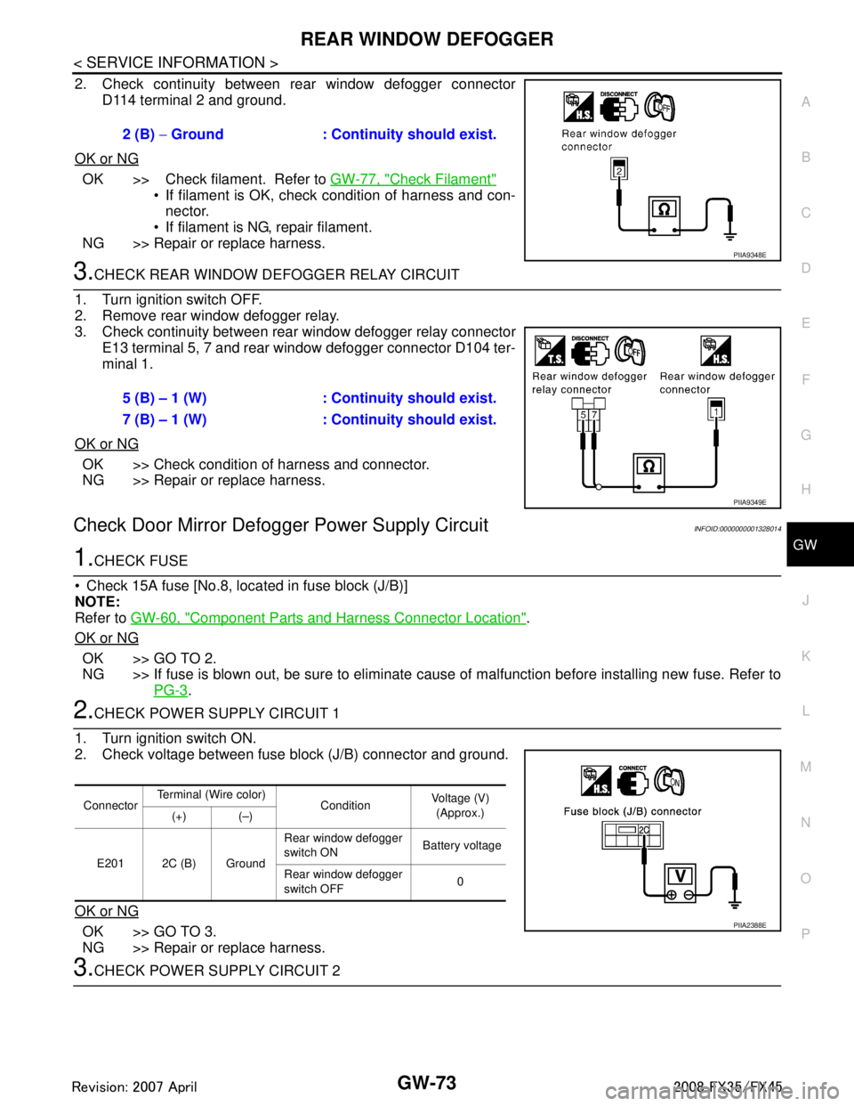
2. Check continuity between rear window defogger connector D114 terminal 2 and ground.
OK or NG
OK >> Check filament. Refer to GW-77, "Check Filament"
If filament is OK, check condition of harness and con-
nector.
If filament is NG, repair filament.
NG >> Repair or replace harness.
3.CHECK REAR WINDOW DEFOGGER RELAY CIRCUIT
1. Turn ignition switch OFF.
2. Remove rear window defogger relay.
3. Check continuity between rear window defogger relay connector E13 terminal 5, 7 and rear window defogger connector D104 ter-
minal 1.
OK or NG
OK >> Check condition of harness and connector.
NG >> Repair or replace harness.
Check Door Mirror Defogger Power Supply CircuitINFOID:0000000001328014
1.CHECK FUSE
Check 15A fuse [No.8, loca ted in fuse block (J/B)]
NOTE:
Refer to GW-60, "
Component Parts and Harness Connector Location".
OK or NG
OK >> GO TO 2.
NG >> If fuse is blown out, be sure to eliminate c ause of malfunction before installing new fuse. Refer to
PG-3
.
2.CHECK POWER SUPPLY CIRCUIT 1
1. Turn ignition switch ON.
2. Check voltage between fuse block (J/B) connector and ground.
OK or NG
OK >> GO TO 3.
NG >> Repair or replace harness.
3.CHECK POWER SUPPLY CIRCUIT 2 2 (B)
− Ground : Continuity should exist.
PIIA9348E
5 (B) – 1 (W) : Cont inuity should exist.
7 (B) – 1 (W) : Cont inuity should exist.
PIIA9349E
ConnectorTerminal (Wire color)
ConditionVoltage (V)
(Approx.)
(+) (–)
E201 2C (B) Ground Rear window defogger
switch ON
Battery voltage
Rear window defogger
switch OFF 0
PIIA2388E
3AA93ABC3ACD3AC03ACA3AC03AC63AC53A913A773A893A873A873A8E3A773A983AC73AC93AC03AC3
3A893A873A873A8F3A773A9D3AAF3A8A3A8C3A863A9D3AAF3A8B3A8C
Page 2987 of 3924
GW-74
< SERVICE INFORMATION >
REAR WINDOW DEFOGGER
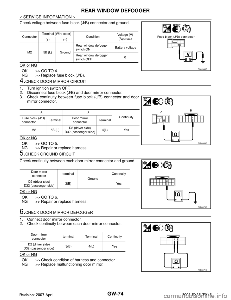
Check voltage between fuse block (J/B) connector and ground.
OK or NG
OK >> GO TO 4.
NG >> Replace fuse block (J/B).
4.CHECK DOOR MIRROR CIRCUIT
1. Turn ignition switch OFF.
2. Disconnect fuse block (J/B) and door mirror connector.
3. Check continuity between fuse block (J/B) connector and door mirror connector.
OK or NG
OK >> GO TO 5.
NG >> Repair or replace harness.
5.CHECK GROUND CIRCUIT
Check continuity between each door mirror connector and ground.
OK or NG
OK >> GO TO 6.
NG >> Repair or replace harness.
6.CHECK DOOR MIRROR DEFOGGER
1. Connect door mirror connector.
2. Check continuity between each door mirror connector.
OK or NG
OK >> Check condition of harness and connector.
NG >> Replace malfunctioning door mirror.
Connector Terminal (Wire color)
ConditionVoltage (V)
(Approx.)
(+) (–)
M2 5B (L) Ground Rear window defogger
switch ON
Battery voltage
Rear window defogger
switch OFF 0
PIIA2386E
AB
Continuity
Fuse block (J/B)
connector Te r m i n a lDoor mirror
connector Te r m i n a l
M2 5B (L) D2 (driver side)
D32 (passenger side) 4(L) Yes
PIIB8569E
Door mirror
connector terminal
GroundContinuity
D2 (driver side)
D32 (passenger side) 3(B) Yes
PIIB8570E
Door mirror
connector terminal Terminal Continuity
D2 (driver side)
D32 (passenger side) 3(B) 4(L) Yes
PIIB8571E
3AA93ABC3ACD3AC03ACA3AC03AC63AC53A913A773A893A873A873A8E3A773A983AC73AC93AC03AC3
3A893A873A873A8F3A773A9D3AAF3A8A3A8C3A863A9D3AAF3A8B3A8C
Page 2988 of 3924
REAR WINDOW DEFOGGERGW-75
< SERVICE INFORMATION >
C
DE
F
G H
J
K L
M A
B
GW
N
O P
Check Driver Side Door Mirror Defogger CircuitINFOID:0000000001328015
1.CHECK POWER SUPPLY CIRCUIT
1. Turn ignition switch OFF.
2. Disconnect door mirror (driver side) connector.
3. Turn ignition switch ON.
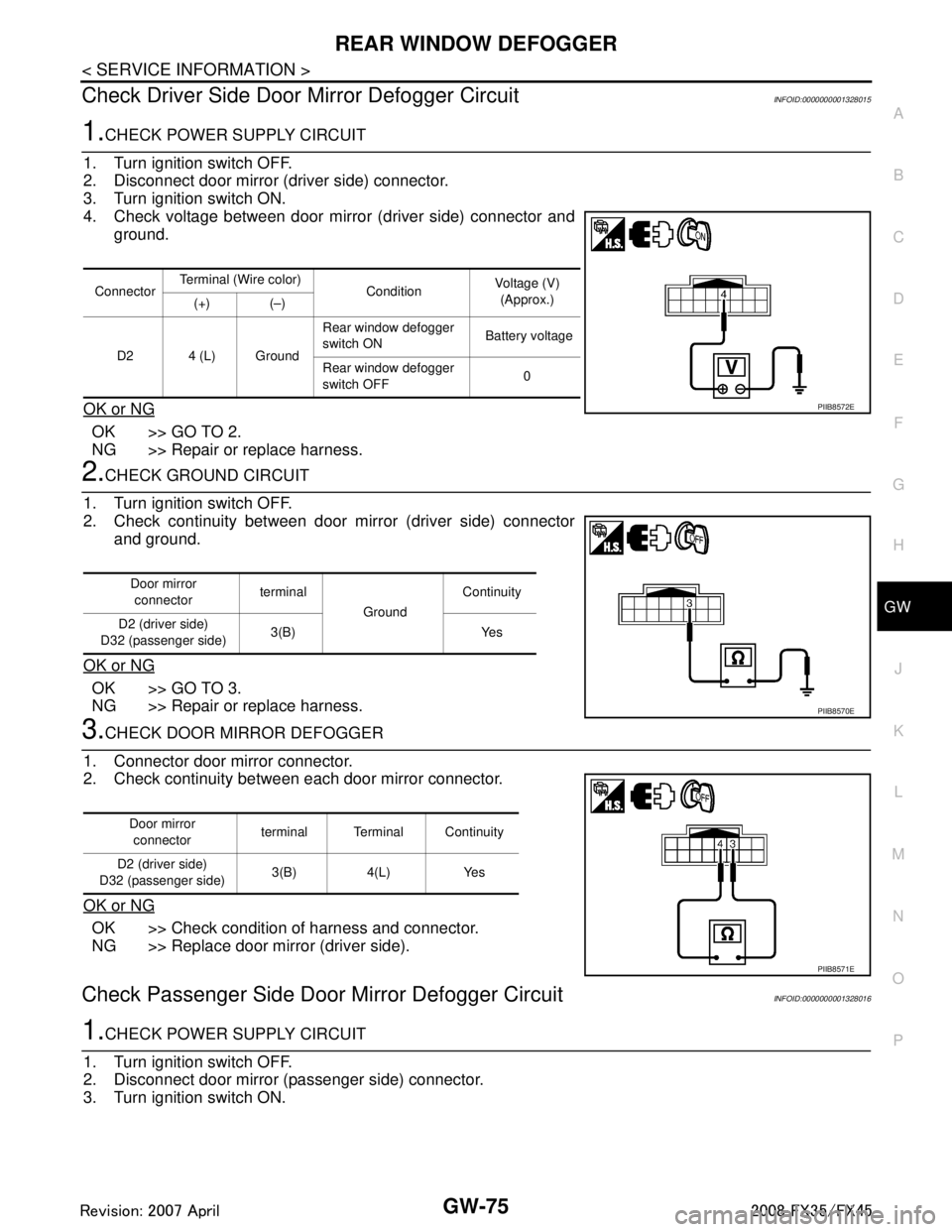
4. Check voltage between door mirror (driver side) connector and ground.
OK or NG
OK >> GO TO 2.
NG >> Repair or replace harness.
2.CHECK GROUND CIRCUIT
1. Turn ignition switch OFF.
2. Check continuity between door mirror (driver side) connector and ground.
OK or NG
OK >> GO TO 3.
NG >> Repair or replace harness.
3.CHECK DOOR MIRROR DEFOGGER
1. Connector door mirror connector.
2. Check continuity between each door mirror connector.
OK or NG
OK >> Check condition of harness and connector.
NG >> Replace door mirror (driver side).
Check Passenger Si de Door Mirror Defogger CircuitINFOID:0000000001328016
1.CHECK POWER SUPPLY CIRCUIT
1. Turn ignition switch OFF.
2. Disconnect door mirror (passenger side) connector.
3. Turn ignition switch ON.
Connector Terminal (Wire color)
ConditionVoltage (V)
(Approx.)
(+) (–)
D2 4 (L) Ground Rear window defogger
switch ON
Battery voltage
Rear window defogger
switch OFF 0
PIIB8572E
Door mirror
connector terminal
GroundContinuity
D2 (driver side)
D32 (passenger side) 3(B) Yes
PIIB8570E
Door mirror
connector terminal Terminal Continuity
D2 (driver side)
D32 (passenger side) 3(B) 4(L) Yes
PIIB8571E
3AA93ABC3ACD3AC03ACA3AC03AC63AC53A913A773A893A873A873A8E3A773A983AC73AC93AC03AC3
3A893A873A873A8F3A773A9D3AAF3A8A3A8C3A863A9D3AAF3A8B3A8C
Page 2989 of 3924

GW-76
< SERVICE INFORMATION >
REAR WINDOW DEFOGGER
4. Check voltage between door mirror (passenger side) connectorand ground.
OK or NG
OK >> GO TO 2.
NG >> Repair or replace harness.
2.CHECK GROUND CIRCUIT
1. Turn ignition switch OFF.
2. Check continuity between door mirror (passenger side) connec- tor and ground.
OK or NG
OK >> GO TO 3.
NG >> Repair or replace harness.
3.CHECK DOOR MIRROR DEFOGGER
1. Connector door mirror connector.
2. Check continuity between each door mirror connector.
OK or NG
OK >> Check condition of harness and connector.
NG >> Replace door mirror (passenger side).
Check Rear Windo w Defogger SignalINFOID:0000000001328017
1.CHECK REAR WINDOW DEFOGGER SWITCH LAMP
A/C and AV switch self-diagnosis is performed. Refer to AV-34, "
A/C and AV Switch Self-Diagnosis Function"
Does rear window defogger switch light?
YES >> GO TO 2.
NO >> Replace A/C and AV switch.
2.CHECK AV COMMUNICATION LINE
AV communication line check is performed. Refer to AV-79, "
Unable to Operate System with A/C and AV
Switch"
Is rear window defogger displayed on the display?
YES >> GO TO 3.
NO >> Replace display control unit.
3.CHECK CAN COMMUNICATION LINE
ConnectorTerminal (Wire color)
ConditionVoltage (V)
(Approx.)
(+) (–)
D32 4 (L) Ground Rear window defogger
switch ON
Battery voltage
Rear window defogger
switch OFF 0
PIIB8572E
Door mirror
connector terminal
GroundContinuity
D2 (driver side)
D32 (passenger side) 3(B) Yes
PIIB8570E
Door mirror
connector terminal Terminal Continuity
D2 (driver side)
D32 (passenger side) 3(B) 4(L) Yes
PIIB8571E
3AA93ABC3ACD3AC03ACA3AC03AC63AC53A913A773A893A873A873A8E3A773A983AC73AC93AC03AC3
3A893A873A873A8F3A773A9D3AAF3A8A3A8C3A863A9D3AAF3A8B3A8C
Page 2990 of 3924
REAR WINDOW DEFOGGERGW-77
< SERVICE INFORMATION >
C
DE
F
G H
J
K L
M A
B
GW
N
O P
CAN communication line check is performed. Refer to AV-79, "CAN Communication Check".
OK or NG
OK >> Check condition of harness and connector.
NG >> In addition, it is necessary to check CAN communication line. Refer to AV-79, "
CAN Communica-
tion Check".
Check FilamentINFOID:0000000001328018
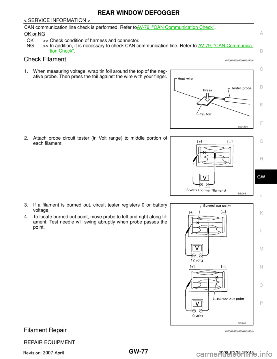
1. When measuring voltage, wrap tin foil around the top of the neg-
ative probe. Then press the foil against the wire with your finger.
2. Attach probe circuit tester (in Volt range) to middle portion of each filament.
3. If a filament is burned out, circuit tester registers 0 or battery voltage.
4. To locate burned out point, move probe to left and right along fil- ament. Test needle will swing abruptly when probe passes the
point.
Filament RepairINFOID:0000000001328019
REPAIR EQUIPMENT
SEL122R
SEL263
SEL265
3AA93ABC3ACD3AC03ACA3AC03AC63AC53A913A773A893A873A873A8E3A773A983AC73AC93AC03AC3
3A893A873A873A8F3A773A9D3AAF3A8A3A8C3A863A9D3AAF3A8B3A8C
Page 3003 of 3924
IP-2
< SERVICE INFORMATION >
PRECAUTIONS
SERVICE INFORMATION
PRECAUTIONS
Precaution for Supplemental Restraint System (SRS) "AIR BAG" and "SEAT BELT
PRE-TENSIONER"
INFOID:0000000001612902
The Supplemental Restraint System such as “A IR BAG” and “SEAT BELT PRE-TENSIONER”, used along
with a front seat belt, helps to reduce the risk or severi ty of injury to the driver and front passenger for certain
types of collision. This system includes seat belt switch inputs and dual stage front air bag modules. The SRS
system uses the seat belt switches to determine the front air bag deployment, and may only deploy one front
air bag, depending on the severity of a collision and w hether the front occupants are belted or unbelted.
Information necessary to service the system safely is included in the “SUPPLEMENTAL RESTRAINT SYS-
TEM” and “SEAT BELTS” of this Service Manual.
WARNING:
• To avoid rendering the SRS inopera tive, which could increase the risk of personal injury or death in
the event of a collision which would result in air bag inflation, all maintenance must be performed by
an authorized NISS AN/INFINITI dealer.
Improper maintenance, including in correct removal and installation of the SRS, can lead to personal
injury caused by unintent ional activation of the system. For re moval of Spiral Cable and Air Bag
Module, see the “SUPPLEMEN TAL RESTRAINT SYSTEM”.
Do not use electrical test equipmen t on any circuit related to the SRS unless instructed to in this
Service Manual. SRS wiring harnesses can be identi fied by yellow and/or orange harnesses or har-
ness connectors.
PrecautionINFOID:0000000001328081
Disconnect both battery cables in advance.
Disconnect air bag system line in advance.
Never tamper with or force air bag lid open, as this may adversely affect air bag performance.
Be careful not to scratch pad and other parts.
When removing or disassembling any part, be careful not to damage or deform it. Protect parts, which may get in the way with cloth.
When removing parts with a screwdriver or other tool, protect parts by wrapping them with vinyl or tape.
Keep removed parts protected with cloth.
If a clip is deformed or damaged, replace it.
If an unreusable part is removed, replace it with a new one.
Tighten bolts and nuts firmly to the specified torque.
After re-assembly has been completed, make sure each part functions correctly.
Remove stains in the following way.
Water-soluble stains:
Dip a soft cloth in warm water, and then squeeze it tightly. After wiping the stain, wipe with a soft dry cloth.
Oil stain:
Dissolve a synthetic detergent in warm water (density of 2 to 3% or less), dip the cloth, then clean off the stain
with the cloth. Next, dip the cloth in fresh water and squeeze it tightly. Then clean off the detergent completely.
Then wipe the area with a soft dry cloth.
Do not use any organic solvent, such as thinner or benzine.
3AA93ABC3ACD3AC03ACA3AC03AC63AC53A913A773A893A873A873A8E3A773A983AC73AC93AC03AC3
3A893A873A873A8F3A773A9D3AAF3A8A3A8C3A863A9D3AAF3A8B3A8C
Page 3012 of 3924
INSTRUMENT PANEL ASSEMBLYIP-11
< SERVICE INFORMATION >
C
DE
F
G H
J
K L
M A
B
IP
N
O P
Removal and InstallationINFOID:0000000001328088
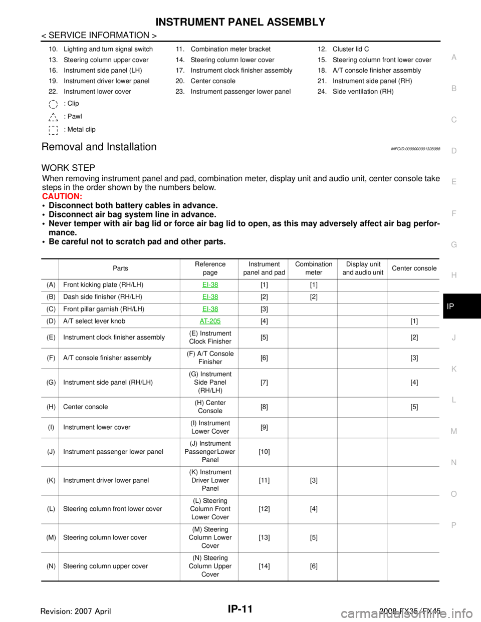
WORK STEP
When removing instrument panel and pad, combination me ter, display unit and audio unit, center console take
steps in the order shown by the numbers below.
CAUTION:
Disconnect both battery cables in advance.
Disconnect air bag system line in advance.
Never temper with air bag lid or force air bag lid to open, as this may adversely affect air bag perfor-
mance.
Be careful not to scratch pad and other parts.
10. Lighting and turn signal switch 11. Combination meter bracket 12. Cluster lid C
13. Steering column upper cover 14. Steering column lower cover 15. Steering column front lower cover
16. Instrument side panel (LH) 17. Instrument clock finisher assembly 18. A/T console finisher assembly
19. Instrument driver lower panel 20. Center console 21. Instrument side panel (RH)
22. Instrument lower cover 23. Instrument passenger lower panel 24. Side ventilation (RH)
: Clip
: Pawl
: Metal clip
Parts Reference
page Instrument
panel and pad Combination
meter Display unit
and audio unit Center console
(A) Front kicking plate (RH/LH) EI-38
[1] [1]
(B) Dash side finisher (RH/LH) EI-38
[2] [2]
(C) Front pillar garnish (RH/LH) EI-38
[3]
(D) A/T select lever knob AT- 2 0 5
[4] [1]
(E) Instrument clock finisher assembly (E) Instrument
Clock Finisher [5] [2]
(F) A/T console finisher assembly (F) A/T Console
Finisher [6] [3]
(G) Instrument side panel (RH/LH) (G) Instrument
Side Panel (RH/LH) [7] [4]
(H) Center console (H) Center
Console [8] [5]
(I) Instrument lower cover (I) Instrument
Lower Cover [9]
(J) Instrument passenger lower panel (J) Instrument
Passenger Lower
Panel [10]
(K) Instrument driver lower panel (K) Instrument
Driver Lower Panel [11] [3]
(L) Steering column front lower cover (L) Steering
Column Front Lower Cover [12] [4]
(M) Steering column lower cover (M) Steering
Column Lower
Cover [13] [5]
(N) Steering column upper cover (N) Steering
Column Upper Cover [14] [6]
3AA93ABC3ACD3AC03ACA3AC03AC63AC53A913A773A893A873A873A8E3A773A983AC73AC93AC03AC3
3A893A873A873A8F3A773A9D3AAF3A8A3A8C3A863A9D3AAF3A8B3A8C