2008 INFINITI FX35 battery
[x] Cancel search: batteryPage 2947 of 3924
GW-34
< SERVICE INFORMATION >
POWER WINDOW SYSTEM
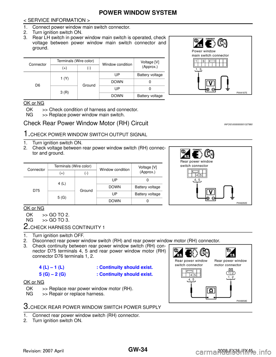
1. Connect power window main switch connector.
2. Turn ignition switch ON.
3. Rear LH switch in power window main switch is operated, checkvoltage between power window main switch connector and
ground.
OK or NG
OK >> Check condition of harness and connector.
NG >> Replace power window main switch.
Check Rear Power Windo w Motor (RH) CircuitINFOID:0000000001327980
1.CHECK POWER WINDOW SWITCH OUTPUT SIGNAL
1. Turn ignition switch ON.
2. Check voltage between rear power window switch (RH) connec- tor and ground.
OK or NG
OK >> GO TO 2.
NG >> GO TO 3.
2.CHECK HARNESS CONTINUITY 1
1. Turn ignition switch OFF.
2. Disconnect rear power window switch (RH) and rear power window motor (RH) connector.
3. Check continuity between rear power window switch (RH) con- nector D75 terminals 4, 5 and rear power window motor (RH)
connector D76 terminals 1, 2.
OK or NG
OK >> Replace rear power window motor (RH).
NG >> Repair or replace harness.
3.CHECK REAR POWER WINDOW SWITCH POWER SUPPLY
1. Connect rear power window switch (RH) connector.
2. Turn ignition switch ON.
Connector Terminals (Wire color)
Window conditionVoltage [V]
(Approx.)
(+) (-)
D6 1 (Y)
Ground UP Battery voltage
DOWN 0
3 (R) UP 0
DOWN Battery voltage
PIIA4187E
Connector Terminals (Wire color)
Window conditionVoltage [V]
(Approx.)
(+) (-)
D75 4 (L)
Ground UP 0
DOWN Battery voltage
5 (G) UP Battery voltage
DOWN 0
PIIA6282E
4 (L) – 1 (L) : Conti nuity should exist.
5 (G) – 2 (G) : Conti nuity should exist.
PIIA9958E
3AA93ABC3ACD3AC03ACA3AC03AC63AC53A913A773A893A873A873A8E3A773A983AC73AC93AC03AC3
3A893A873A873A8F3A773A9D3AAF3A8A3A8C3A863A9D3AAF3A8B3A8C
Page 2948 of 3924

POWER WINDOW SYSTEMGW-35
< SERVICE INFORMATION >
C
DE
F
G H
J
K L
M A
B
GW
N
O P
3. Check voltage between rear power window switch (RH) connec- tor D75 terminal 1 and ground.
OK or NG
OK >> GO TO 5.
NG >> GO TO 4.
4.CHECK HARNESS CONTINUITY 2
1. Turn ignition switch OFF.
2. Disconnect BCM and rear power window switch (RH) connector.
3. Check continuity between BCM connector M4 terminal 53 and rear power window switch (RH) connector D75 terminal 1.
4. Check continuity between BCM connector M4 terminal 53 and ground.
OK or NG
OK >> Check condition of harness and connector.
NG >> Repair or replace harness.
5.CHECK REAR POWER WINDOW SWITCH
1. Turn ignition switch OFF.
2. Disconnect rear power window switch connector.
3. Rear power window switch (RH) operate, check continuity between rear power window switch terminals1, 2, 3 and 4, 5.
OK or NG
OK >> GO TO 6.
NG >> Replace rear power window switch (RH).
6.CHECK HARNESS CONTINUITY 3
1. Disconnect power window main switch connector.
2. Check continuity between power window main switch connector D6 terminals 5, 7 and rear power window switch (RH) connector
D75 terminals 2, 3.
OK or NG
OK >> GO TO 7.
NG >> Repair or replace harness.
7.CHECK POWER WINDOW MAIN SWITCH OUTPUT SIGNAL 1 (BR) – Ground : Battery voltage
PIIA4185E
53 (Y/B) – 1 (BR) : Continuity should exist.
53 (Y/B) – Ground : Continuity should not exist.
PIIA6284E
Terminals Window condition Continuity
15 UP
Ye s
14 DOWN
2 5 No operation
3 4 No operation
PIIA4186E
5 (G) – 3 (R) : Continuity should exist.
7 (LG) – 2 (Y) : Cont
inuity should exist.
PIIA4190E
3AA93ABC3ACD3AC03ACA3AC03AC63AC53A913A773A893A873A873A8E3A773A983AC73AC93AC03AC3
3A893A873A873A8F3A773A9D3AAF3A8A3A8C3A863A9D3AAF3A8B3A8C
Page 2949 of 3924
GW-36
< SERVICE INFORMATION >
POWER WINDOW SYSTEM
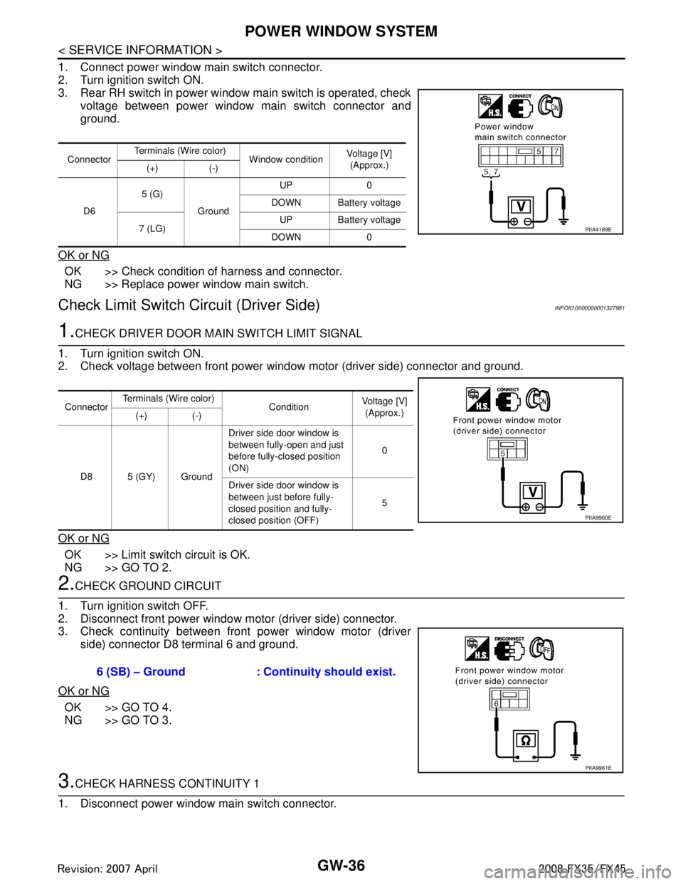
1. Connect power window main switch connector.
2. Turn ignition switch ON.
3. Rear RH switch in power window main switch is operated, checkvoltage between power window main switch connector and
ground.
OK or NG
OK >> Check condition of harness and connector.
NG >> Replace power window main switch.
Check Limit Switch Circuit (Driver Side)INFOID:0000000001327981
1.CHECK DRIVER DOOR MAIN SWITCH LIMIT SIGNAL
1. Turn ignition switch ON.
2. Check voltage between front power window motor (driver side) connector and ground.
OK or NG
OK >> Limit switch circuit is OK.
NG >> GO TO 2.
2.CHECK GROUND CIRCUIT
1. Turn ignition switch OFF.
2. Disconnect front power window motor (driver side) connector.
3. Check continuity between front power window motor (driver side) connector D8 terminal 6 and ground.
OK or NG
OK >> GO TO 4.
NG >> GO TO 3.
3.CHECK HARNESS CONTINUITY 1
1. Disconnect power window main switch connector.
Connector Terminals (Wire color)
Window conditionVoltage [V]
(Approx.)
(+) (-)
D6 5 (G)
Ground UP 0
DOWN Battery voltage
7 (LG) UP Battery voltage
DOWN 0
PIIA4189E
Connector Terminals (Wire color)
Condition Voltage [V]
(Approx.)
(+) (-)
D8 5 (GY) Ground Driver side door window is
between fully-open and just
before fully-closed position
(ON)
0
Driver side door window is
between just before fully-
closed position and fully-
closed position (OFF) 5
PIIA9960E
6 (SB) – Ground : Continuity should exist.
PIIA9961E
3AA93ABC3ACD3AC03ACA3AC03AC63AC53A913A773A893A873A873A8E3A773A983AC73AC93AC03AC3
3A893A873A873A8F3A773A9D3AAF3A8A3A8C3A863A9D3AAF3A8B3A8C
Page 2955 of 3924
GW-42
< SERVICE INFORMATION >
POWER WINDOW SYSTEM
OK >> Replace front power window switch (passenger side).
NG >> GO TO 6.
6.CHECK HARNESS CONTINUITY 3
1. Turn ignition switch OFF.
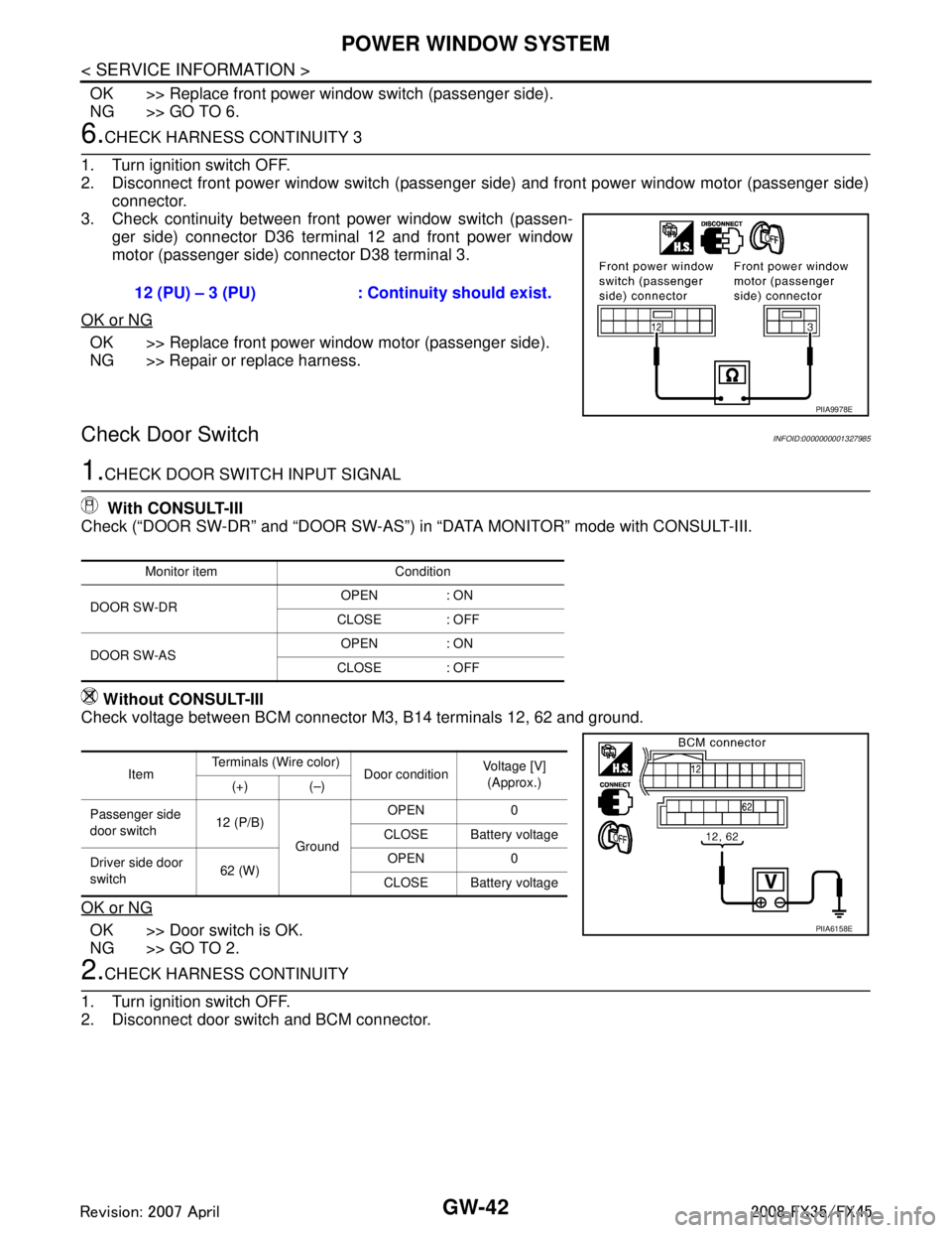
2. Disconnect front power window switch (passenger side) and front power window motor (passenger side) connector.
3. Check continuity between front power window switch (passen- ger side) connector D36 terminal 12 and front power window
motor (passenger side) connector D38 terminal 3.
OK or NG
OK >> Replace front power window motor (passenger side).
NG >> Repair or replace harness.
Check Door SwitchINFOID:0000000001327985
1.CHECK DOOR SWITCH INPUT SIGNAL
With CONSULT-III
Check (“DOOR SW-DR” and “DOOR SW-AS”) in “DATA MONITOR” mode with CONSULT-III.
Without CONSULT-III
Check voltage between BCM connector M3, B14 terminals 12, 62 and ground.
OK or NG
OK >> Door switch is OK.
NG >> GO TO 2.
2.CHECK HARNESS CONTINUITY
1. Turn ignition switch OFF.
2. Disconnect door switch and BCM connector. 12 (PU) – 3 (PU) : Continuity should exist.
PIIA9978E
Monitor item Condition
DOOR SW-DR OPEN : ON
CLOSE : OFF
DOOR SW-AS OPEN : ON
CLOSE : OFF
Item Terminals (Wire color)
Door conditionVoltage [V]
(Approx.)
(+) (–)
Passenger side
door switch 12 (P/B)
Ground OPEN 0
CLOSE Battery voltage
Driver side door
switch 62 (W) OPEN 0
CLOSE Battery voltage
PIIA6158E
3AA93ABC3ACD3AC03ACA3AC03AC63AC53A913A773A893A873A873A8E3A773A983AC73AC93AC03AC3
3A893A873A873A8F3A773A9D3AAF3A8A3A8C3A863A9D3AAF3A8B3A8C
Page 2956 of 3924
POWER WINDOW SYSTEMGW-43
< SERVICE INFORMATION >
C
DE
F
G H
J
K L
M A
B
GW
N
O P
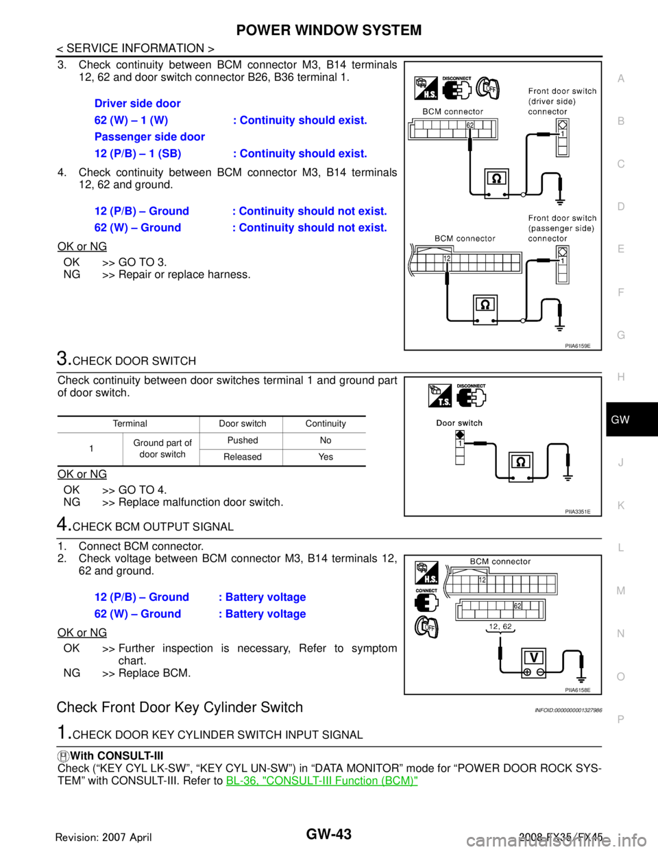
3. Check continuity between BCM connector M3, B14 terminals 12, 62 and door switch connector B26, B36 terminal 1.
4. Check continuity between BCM connector M3, B14 terminals 12, 62 and ground.
OK or NG
OK >> GO TO 3.
NG >> Repair or replace harness.
3.CHECK DOOR SWITCH
Check continuity between door switches terminal 1 and ground part
of door switch.
OK or NG
OK >> GO TO 4.
NG >> Replace malfunction door switch.
4.CHECK BCM OUTPUT SIGNAL
1. Connect BCM connector.
2. Check voltage between BCM connector M3, B14 terminals 12, 62 and ground.
OK or NG
OK >> Further inspection is necessary, Refer to symptom chart.
NG >> Replace BCM.
Check Front Door Key Cylinder SwitchINFOID:0000000001327986
1.CHECK DOOR KEY CYLINDER SWITCH INPUT SIGNAL
With CONSULT-III
Check (“KEY CYL LK-SW”, “KEY CYL UN-SW”) in “D ATA MONITOR” mode for “POWER DOOR ROCK SYS-
TEM” with CONSULT-III. Refer to BL-36, "
CONSULT-III Function (BCM)"
Driver side door
62 (W) – 1 (W) : Continuity should exist.
Passenger side door
12 (P/B) – 1 (SB) : Continuity should exist.
12 (P/B) – Ground : Contin uity should not exist.
62 (W) – Ground : Contin uity should not exist.
PIIA6159E
Terminal Door switch Continuity
1 Ground part of
door switch Pushed No
Released Yes
PIIA3351E
12 (P/B) – Ground : Battery voltage
62 (W) – Ground : Battery voltage
PIIA6158E
3AA93ABC3ACD3AC03ACA3AC03AC63AC53A913A773A893A873A873A8E3A773A983AC73AC93AC03AC3
3A893A873A873A8F3A773A9D3AAF3A8A3A8C3A863A9D3AAF3A8B3A8C
Page 2980 of 3924

REAR WINDOW DEFOGGERGW-67
< SERVICE INFORMATION >
C
DE
F
G H
J
K L
M A
B
GW
N
O P
Terminal and Reference Value for BCMINFOID:0000000001328004
Terminal and Reference Value for IPDM E/RINFOID:0000000001328005
CONSULT-III Function (BCM)INFOID:0000000001328006
DATA MONITOR
ACTIVE TEST
Te r m i n a l Wire col-
or ItemSignal In-
put/
Output Condition
Voltage (V)
(Approx.)
9L/W Rear window defogger
switch signal InputWhen rear window defogger switch is
pressed.
0
When rear window defogger switch is OFF. 5
38 W/L Ignition switch ON or START Input Ignition switch (ON or START position) Battery voltage
39 L CAN − H Input/
Output ——
40 P CAN − L Input/
Output ——
42 L/R Power source (Fuse) Input — Battery voltage
49 B Ground (signal) — — 0
52 B Ground (power) — — 0
55 G Power source (Fusible link) Input — Battery voltage
Te r m i n a l Wire col-
or Item Signal
Input/
Output Condition
Voltage (V)
(Approx.)
5 R Battery power supply Output — Battery voltage
6 W Battery power supply Output — Battery voltage
38 B Ground (Power) — — 0
48 L CAN − H Input/
Output ——
49 R CAN − L Input/
Output ——
52 G Rear window defogger relay
control signal
InputWhen rear window defogger switch is ON. 0
When rear window defogger switch is
OFF.
Battery voltage
60 B Ground (Signal) — — 0
BCM diagnostic test item Check item diagnostic test mode Content
REAR DEFOGGER Data monitor Displays the input data of BCM in real time.
Active test Gives a drive signal to a load to check the operation.
Monitor item Content
REAR DEF SW Displays “Press (ON)/others (OFF)” status determined with the rear window defogger switch.
IGN ON SW Displays “IGN (ON)/OFF” status determined with the ignition switch signal.
3AA93ABC3ACD3AC03ACA3AC03AC63AC53A913A773A893A873A873A8E3A773A983AC73AC93AC03AC3
3A893A873A873A8F3A773A9D3AAF3A8A3A8C3A863A9D3AAF3A8B3A8C
Page 2982 of 3924
REAR WINDOW DEFOGGERGW-69
< SERVICE INFORMATION >
C
DE
F
G H
J
K L
M A
B
GW
N
O P
Check BCM Power Supply and Ground CircuitINFOID:0000000001328010
First perform the “SELF-DIAG RESULTS” in “BCM” with CONSULT-III, when perform the each trouble
diagnosis. Refer to BCS-13, "
U1000 CAN Communication Circuit".
1.CHECK FUSE
Check 15A fuse [No.1, located in the fuse block (J/B)]
Check 15A fuse [No.22, located in the fuse block (J/B)]
Check 50A fusible link (letter M located in the fuse and fusible link box).
NOTE:
Refer to GW-60, "
Component Parts and Harness Connector Location".
OK or NG
OK >> GO TO 2.
NG >> If fuse is blown out, be sure to eliminate c ause of malfunction before installing new fuse. Refer to
PG-3
.
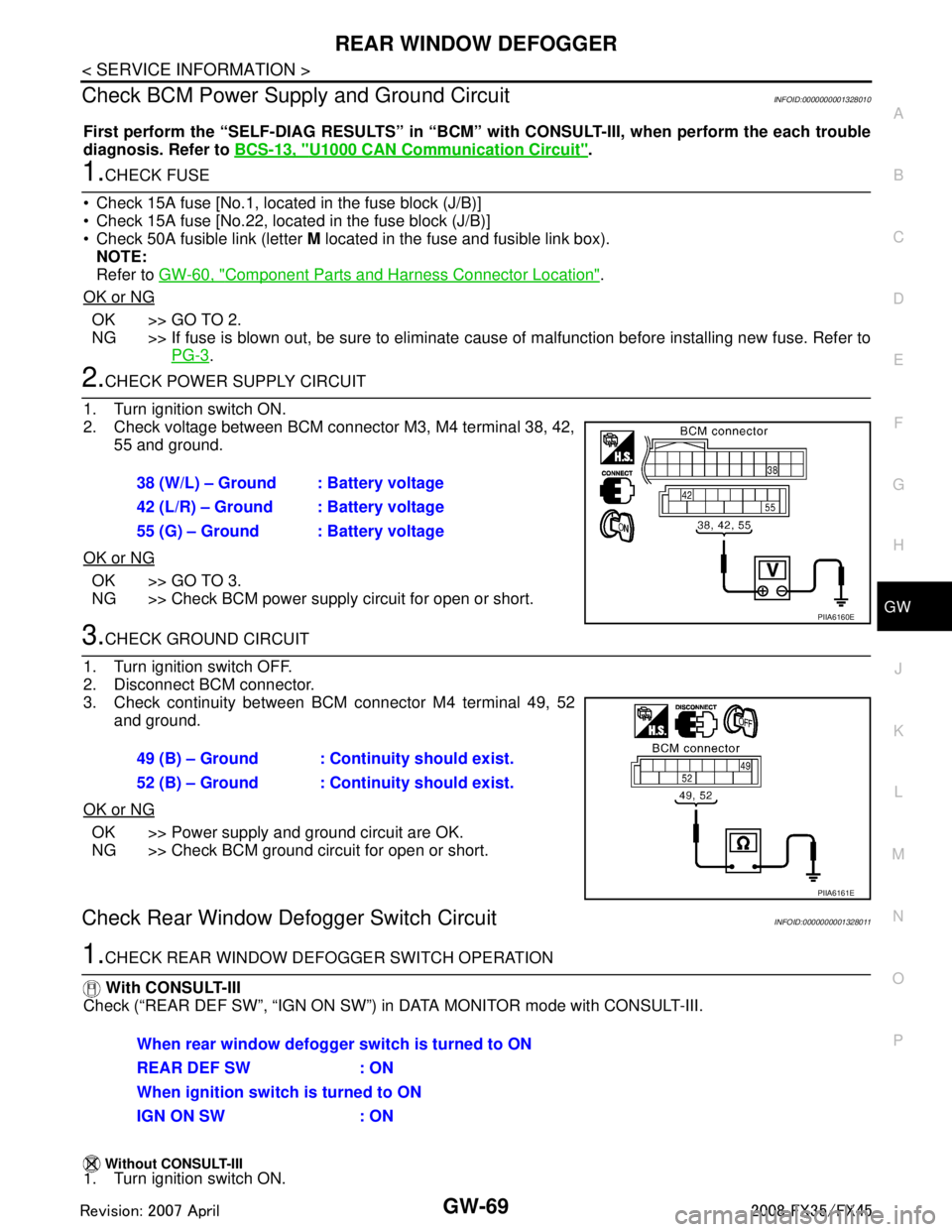
2.CHECK POWER SUPPLY CIRCUIT
1. Turn ignition switch ON.
2. Check voltage between BCM connector M3, M4 terminal 38, 42, 55 and ground.
OK or NG
OK >> GO TO 3.
NG >> Check BCM power supply circuit for open or short.
3.CHECK GROUND CIRCUIT
1. Turn ignition switch OFF.
2. Disconnect BCM connector.
3. Check continuity between BCM connector M4 terminal 49, 52 and ground.
OK or NG
OK >> Power supply and ground circuit are OK.
NG >> Check BCM ground circuit for open or short.
Check Rear Window Defogger Switch CircuitINFOID:0000000001328011
1.CHECK REAR WINDOW DEF OGGER SWITCH OPERATION
With CONSULT-III
Check (“REAR DEF SW”, “IGN ON SW”) in DATA MONITOR mode with CONSULT-III.
Without CONSULT-III1. Turn ignition switch ON. 38 (W/L) – Ground : Battery voltage
42 (L/R) – Ground : Battery voltage
55 (G) – Ground : Battery voltage
PIIA6160E
49 (B) – Ground : Continuity should exist.
52 (B) – Ground : Continuity should exist.
PIIA6161E
When rear window defogger switch is turned to ON
REAR DEF SW : ON
When ignition switch is turned to ON
IGN ON SW : ON
3AA93ABC3ACD3AC03ACA3AC03AC63AC53A913A773A893A873A873A8E3A773A983AC73AC93AC03AC3
3A893A873A873A8F3A773A9D3AAF3A8A3A8C3A863A9D3AAF3A8B3A8C
Page 2984 of 3924
REAR WINDOW DEFOGGERGW-71
< SERVICE INFORMATION >
C
DE
F
G H
J
K L
M A
B
GW
N
O P
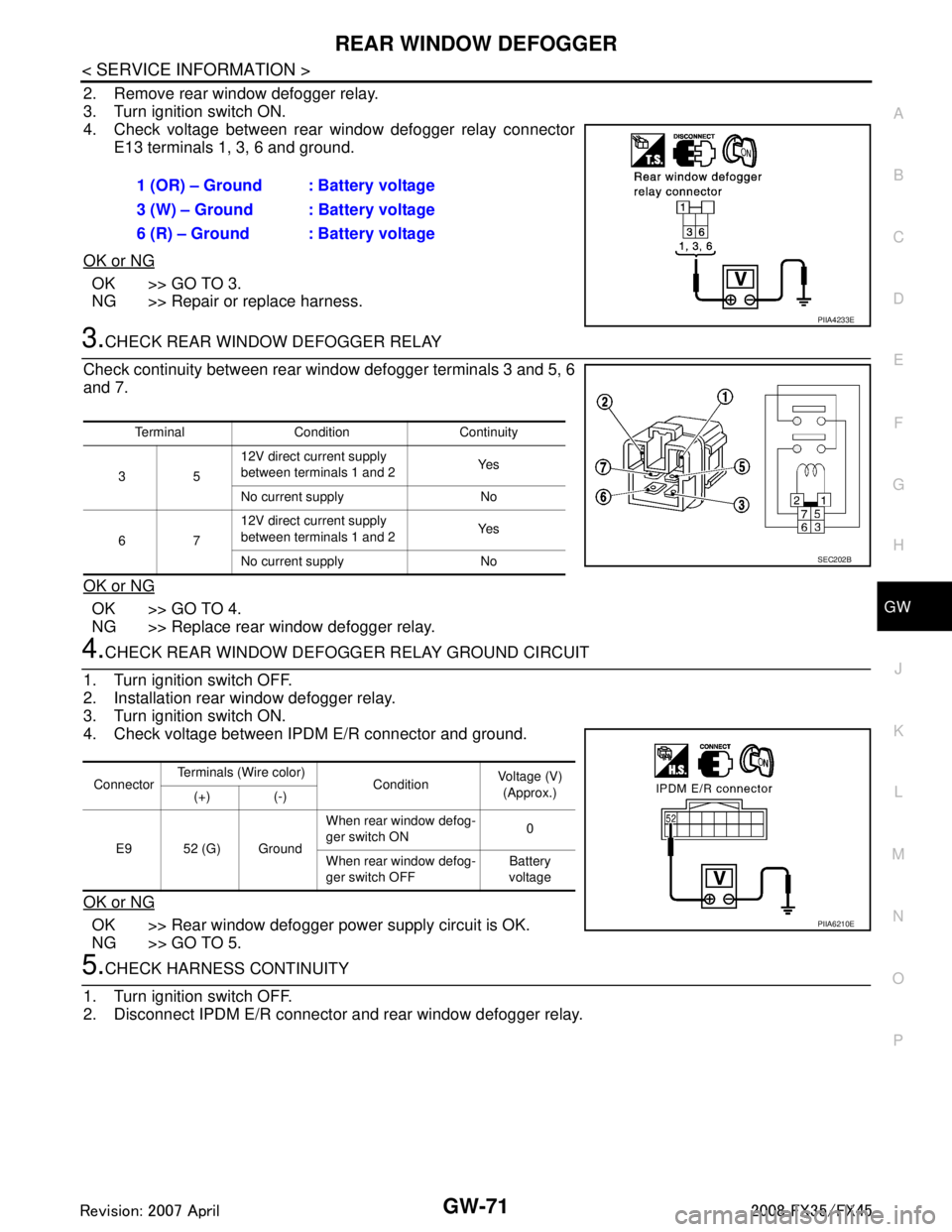
2. Remove rear window defogger relay.
3. Turn ignition switch ON.
4. Check voltage between rear window defogger relay connector E13 terminals 1, 3, 6 and ground.
OK or NG
OK >> GO TO 3.
NG >> Repair or replace harness.
3.CHECK REAR WINDOW DEFOGGER RELAY
Check continuity between rear wi ndow defogger terminals 3 and 5, 6
and 7.
OK or NG
OK >> GO TO 4.
NG >> Replace rear window defogger relay.
4.CHECK REAR WINDOW DEFOGG ER RELAY GROUND CIRCUIT
1. Turn ignition switch OFF.
2. Installation rear window defogger relay.
3. Turn ignition switch ON.
4. Check voltage between IPDM E/R connector and ground.
OK or NG
OK >> Rear window defogger power supply circuit is OK.
NG >> GO TO 5.
5.CHECK HARNESS CONTINUITY
1. Turn ignition switch OFF.
2. Disconnect IPDM E/R connector and rear window defogger relay. 1 (OR) – Ground : Battery voltage
3 (W) – Ground : Battery voltage
6 (R) – Ground : Battery voltage
PIIA4233E
Terminal Condition Continuity
35 12V direct current supply
between terminals 1 and 2
Ye s
No current supply No
67 12V direct current supply
between terminals 1 and 2
Ye s
No current supply No
SEC202B
Connector Terminals (Wire color)
ConditionVoltage (V)
(Approx.)
(+) (-)
E9 52 (G) Ground When rear window defog-
ger switch ON
0
When rear window defog-
ger switch OFF Battery
voltage
PIIA6210E
3AA93ABC3ACD3AC03ACA3AC03AC63AC53A913A773A893A873A873A8E3A773A983AC73AC93AC03AC3
3A893A873A873A8F3A773A9D3AAF3A8A3A8C3A863A9D3AAF3A8B3A8C