2008 INFINITI FX35 battery
[x] Cancel search: batteryPage 2878 of 3924

GI-16
< SERVICE INFORMATION >
HOW TO USE THIS MANUAL
Optional Splice
DESCRIPTION
SGI942
Num-ber Item Description
1 Power condition This shows the condition when the system receives battery positive voltage (can be operated).
2Fusible link The double line shows that this is a fusible link.
The open circle shows current flow in, and the shaded circle shows current flow out.
3 Fusible link/fuse loca-
tion This shows the location of the fusible link or fuse in the fusible link or fuse box. For arrange-
ment, refer to PG section, POWER SUPPLY ROUTING.
4Fuse The single line shows that this is a fuse.
The open circle shows current flow in, and the shaded circle shows current flow out.
5 Current rating This shows the current rating of the fusible link or fuse.
6 Connectors This shows that connector E3 is female and connector M1 is male.
The G/R wire is located in the 1A terminal of both connectors.
Terminal number with an alphabet (1A, 5B, etc.) indicates that the connector is SMJ connector.
Refer to PG section, SMJ (SUPER MULTIPLE JUNCTION).
7 Optional splice The open circle shows that the splice is optional depending on vehicle application.
8 Splice The shaded circle shows that the splice is always on the vehicle.
9 Page crossing This arrow shows that the circuit continues to an adjacent page.
The A will match with the A on the preceding or next page.
10 Common connector The dotted lines between terminals show that these terminals are part of the same connector. 11 Option abbreviation This shows that the circuit is optional depending on vehicle application.
12 Relay This shows an internal representation of the relay. For details, refer to PG section, STAN-
DARDIZED RELAY.
13 Connectors This shows that the connector is connected to the body or a terminal with bolt or nut.
3AA93ABC3ACD3AC03ACA3AC03AC63AC53A913A773A893A873A873A8E3A773A983AC73AC93AC03AC3
3A893A873A873A8F3A773A9D3AAF3A8A3A8C3A863A9D3AAF3A8B3A8C
Page 2890 of 3924
GI-28
< SERVICE INFORMATION >
SERVICE INFORMATION FOR ELECTRICAL INCIDENT
ough understanding of system operation. Then you will be able to use the appropriate equipment and follow
the correct test procedure.
You may have to simulate vehicle vibrations while test ing electrical components. Gently shake the wiring har-
ness or electrical component to do this.
NOTE:
Refer to “How to Check Terminal” to probe or check terminal.
Testing for “Opens” in the Circuit
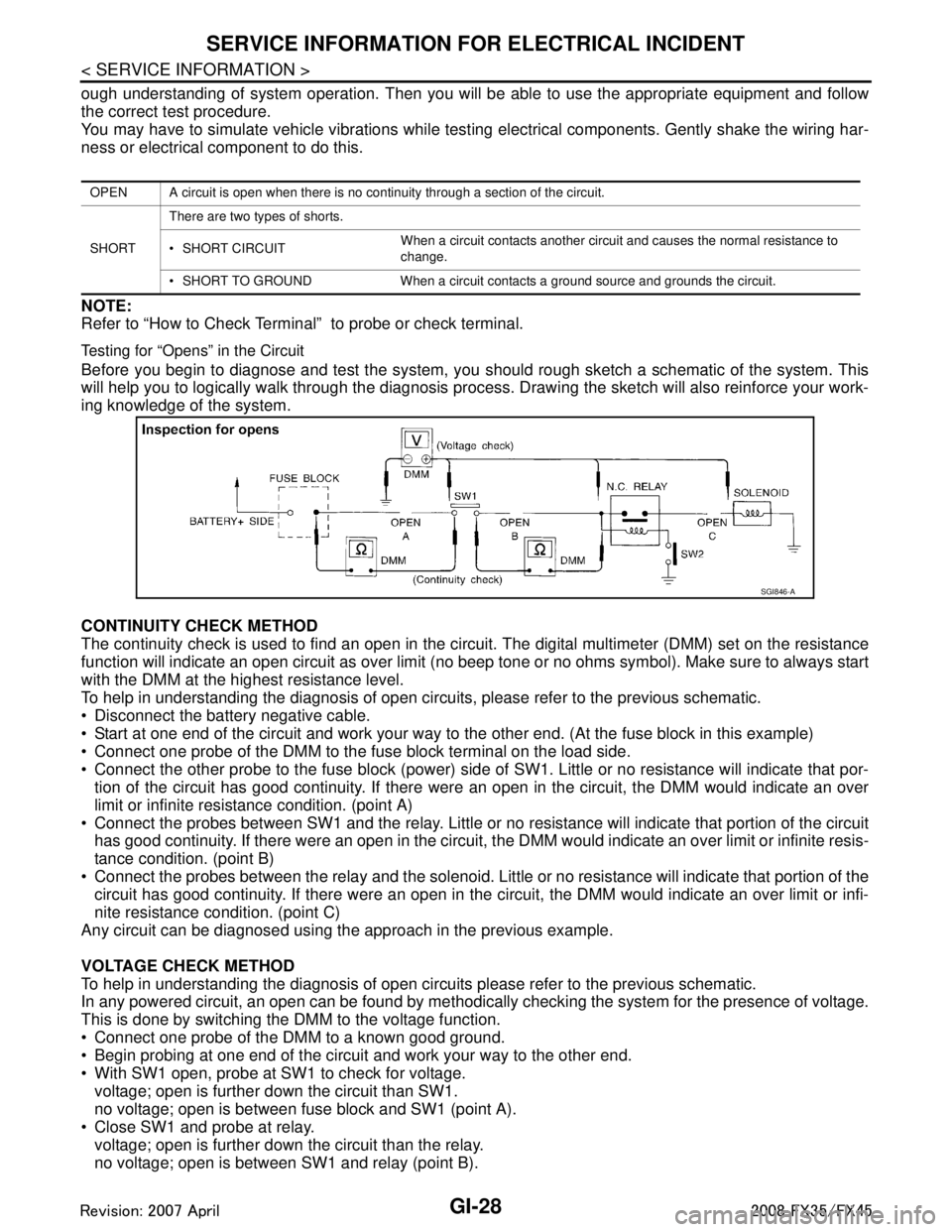
Before you begin to diagnose and test the system, you should rough sketch a schematic of the system. This
will help you to logically walk through the diagnosis process. Drawing the sketch will also reinforce your work-
ing knowledge of the system.
CONTINUITY CHECK METHOD
The continuity check is used to find an open in the circ uit. The digital multimeter (DMM) set on the resistance
function will indicate an open circuit as over limit (no beep tone or no ohms symbo\
l). Make sure to always start
with the DMM at the highest resistance level.
To help in understanding the diagnosis of open circui ts, please refer to the previous schematic.
Disconnect the battery negative cable.
Start at one end of the circuit and work your way to the other end. (At the fuse block in this example)
Connect one probe of the DMM to the fuse block terminal on the load side.
Connect the other probe to the fuse block (power) side of SW1. Little or no resistance will indicate that por-
tion of the circuit has good continuity. If there were an open in the circuit, the DMM would indicate an over
limit or infinite resistance condition. (point A)
Connect the probes between SW1 and the relay. Little or no resistance will indicate that portion of the circuit
has good continuity. If there were an open in the circuit, t he DMM would indicate an over limit or infinite resis-
tance condition. (point B)
Connect the probes between the relay and the solenoid. Little or no resistance will indicate that portion of the
circuit has good continuity. If there were an open in the ci rcuit, the DMM would indicate an over limit or infi-
nite resistance condition. (point C)
Any circuit can be diagnosed using the approach in the previous example.
VOLTAGE CHECK METHOD
To help in understanding the diagnosis of open circui ts please refer to the previous schematic.
In any powered circuit, an open can be found by methodica lly checking the system for the presence of voltage.
This is done by switching the DMM to the voltage function.
Connect one probe of the DMM to a known good ground.
Begin probing at one end of the circuit and work your way to the other end.
With SW1 open, probe at SW1 to check for voltage.
voltage; open is further down the circuit than SW1.
no voltage; open is between fuse block and SW1 (point A).
Close SW1 and probe at relay.
voltage; open is further down the circuit than the relay.
no voltage; open is between SW1 and relay (point B).
OPEN A circuit is open when there is no continuity through a section of the circuit.
SHORT There are two types of shorts.
SHORT CIRCUIT
When a circuit contacts another circuit and causes the normal resistance to
change.
SHORT TO GROUND When a circuit contacts a ground source and grounds the circuit.
SGI846-A
3AA93ABC3ACD3AC03ACA3AC03AC63AC53A913A773A893A873A873A8E3A773A983AC73AC93AC03AC3
3A893A873A873A8F3A773A9D3AAF3A8A3A8C3A863A9D3AAF3A8B3A8C
Page 2891 of 3924
SERVICE INFORMATION FOR ELECTRICAL INCIDENTGI-29
< SERVICE INFORMATION >
C
DE
F
G H
I
J
K L
M B
GI
N
O P
Close the relay and probe at the solenoid. voltage; open is further down the circuit than the solenoid.
no voltage; open is between relay and solenoid (point C).
Any powered circuit can be diagnosed using the approach in the previous example.
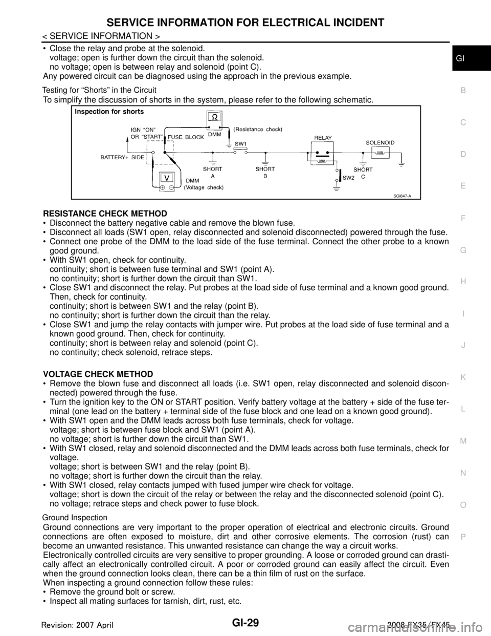
Testing for “Shorts” in the Circuit
To simplify the discussion of shorts in the system, please refer to the following schematic.
RESISTANCE CHECK METHOD
Disconnect the battery negative cable and remove the blown fuse.
Disconnect all loads (SW1 open, relay disconnected and solenoid disconnected) powered through the fuse.
Connect one probe of the DMM to the load side of the fuse terminal. Connect the other probe to a known
good ground.
With SW1 open, check for continuity.
continuity; short is between fuse terminal and SW1 (point A).
no continuity; short is further down the circuit than SW1.
Close SW1 and disconnect the relay. Put probes at the load side of fuse terminal and a known good ground.
Then, check for continuity.
continuity; short is between SW1 and the relay (point B).
no continuity; short is further down the circuit than the relay.
Close SW1 and jump the relay contacts with jumper wir e. Put probes at the load side of fuse terminal and a
known good ground. Then, check for continuity.
continuity; short is between relay and solenoid (point C).
no continuity; check solenoid, retrace steps.
VOLTAGE CHECK METHOD
Remove the blown fuse and disconnect all loads (i .e. SW1 open, relay disconnected and solenoid discon-
nected) powered through the fuse.
Turn the ignition key to the ON or START position. Veri fy battery voltage at the battery + side of the fuse ter-
minal (one lead on the battery + terminal side of the fuse block and one lead on a known good ground).
With SW1 open and the DMM leads across both fuse terminals, check for voltage.
voltage; short is between fuse block and SW1 (point A).
no voltage; short is further down the circuit than SW1.
With SW1 closed, relay and solenoid disconnected and t he DMM leads across both fuse terminals, check for
voltage.
voltage; short is between SW1 and the relay (point B).
no voltage; short is further down the circuit than the relay.
With SW1 closed, relay contacts jumped with fused jumper wire check for voltage.
voltage; short is down the circuit of the relay or between the relay and the disconnected solenoid (point C).
no voltage; retrace steps and check power to fuse block.
Ground Inspection
Ground connections are very important to the proper oper ation of electrical and electronic circuits. Ground
connections are often exposed to moisture, dirt and other corrosive elements. The corrosion (rust) can
become an unwanted resistance. This unwanted re sistance can change the way a circuit works.
Electronically controlled circuits are very sensitive to proper grounding. A loose or corroded ground can drasti-
cally affect an electronically controlled circuit. A poor or corroded ground can easily affect the circuit. Even
when the ground connection looks clean, there can be a thin film of rust on the surface.
When inspecting a ground connection follow these rules:
Remove the ground bolt or screw.
Inspect all mating surfaces for tarnish, dirt, rust, etc.
SGI847-A
3AA93ABC3ACD3AC03ACA3AC03AC63AC53A913A773A893A873A873A8E3A773A983AC73AC93AC03AC3
3A893A873A873A8F3A773A9D3AAF3A8A3A8C3A863A9D3AAF3A8B3A8C
Page 2893 of 3924
SERVICE INFORMATION FOR ELECTRICAL INCIDENTGI-31
< SERVICE INFORMATION >
C
DE
F
G H
I
J
K L
M B
GI
N
O P
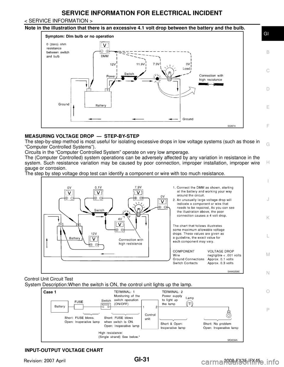
Note in the illustration that there is an excessi ve 4.1 volt drop between the battery and the bulb.
MEASURING VOLTAGE DRO P — STEP-BY-STEP
The step-by-step method is most useful for isolating ex cessive drops in low voltage systems (such as those in
“Computer Controlled Systems”).
Circuits in the “Computer Controlled System” operate on very low amperage.
The (Computer Controlled) system oper ations can be adversely affected by any variation in resistance in the
system. Such resistance variation may be caused by poor connection, improper installation, improper wire
gauge or corrosion.
The step by step voltage drop test can identify a component or wire with too much resistance.
Control Unit Circuit Test
System Description:When the switch is ON, the control unit lights up the lamp.
INPUT-OUTPUT VOLTAGE CHART
SGI974
SAIA0258E
MGI034A
3AA93ABC3ACD3AC03ACA3AC03AC63AC53A913A773A893A873A873A8E3A773A983AC73AC93AC03AC3
3A893A873A873A8F3A773A9D3AAF3A8A3A8C3A863A9D3AAF3A8B3A8C
Page 2894 of 3924
GI-32
< SERVICE INFORMATION >
SERVICE INFORMATION FOR ELECTRICAL INCIDENT
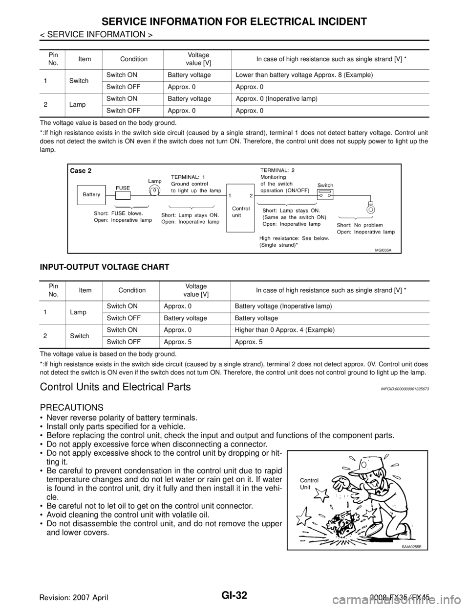
The voltage value is based on the body ground.
*:If high resistance exists in the switch side circuit (caused by a single strand), terminal 1 does not detect battery voltage. Control unit
does not detect the switch is ON even if the switch does not turn ON. Therefore, the control unit does not supply power to ligh t up the
lamp.
INPUT-OUTPUT VOLTAGE CHART
The voltage value is based on the body ground.
*:If high resistance exists in the switch side circuit (caused by a single strand), terminal 2 does not detect approx. 0V. Cont rol unit does
not detect the switch is ON even if the switch does not turn ON. Therefore, the control unit does not control ground to light u p the lamp.
Control Units and Electrical PartsINFOID:0000000001325673
PRECAUTIONS
Never reverse polarity of battery terminals.
Install only parts specified for a vehicle.
Before replacing the control unit, check the input and output and functions of the component parts.
Do not apply excessive force when disconnecting a connector.
Do not apply excessive shock to the control unit by dropping or hit- ting it.
Be careful to prevent condensation in the control unit due to rapid temperature changes and do not let water or rain get on it. If water
is found in the control unit, dry it fully and then install it in the vehi-
cle.
Be careful not to let oil to get on the control unit connector.
Avoid cleaning the control unit with volatile oil.
Do not disassemble the control unit, and do not remove the upper and lower covers.
Pin
No. Item Condition
Vo l ta g e
value [V] In case of high resistance such as single strand [V] *
1Switch Switch ON Battery voltage Lower than battery voltage Approx. 8 (Example)
Switch OFF Approx. 0 Approx. 0
2Lamp Switch ON Battery voltage App
rox. 0 (Inoperative lamp)
Switch OFF Approx. 0 Approx. 0
MGI035A
Pin
No. Item Condition
Vo l ta g e
value [V] In case of high resistance such as single strand [V] *
1Lamp Switch ON Approx. 0 Battery voltage (Inoperative lamp)
Switch OFF Battery voltage Battery voltage
2Switch Switch ON Approx. 0 Higher than 0 Approx. 4 (Example)
Switch OFF Approx. 5 Approx. 5
SAIA0255E
3AA93ABC3ACD3AC03ACA3AC03AC63AC53A913A773A893A873A873A8E3A773A983AC73AC93AC03AC3
3A893A873A873A8F3A773A9D3AAF3A8A3A8C3A863A9D3AAF3A8B3A8C
Page 2895 of 3924
SERVICE INFORMATION FOR ELECTRICAL INCIDENTGI-33
< SERVICE INFORMATION >
C
DE
F
G H
I
J
K L
M B
GI
N
O P
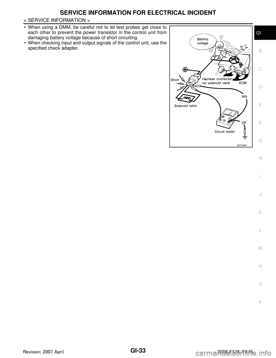
When using a DMM, be careful not to let test probes get close to each other to prevent the power transistor in the control unit from
damaging battery voltage because of short circuiting.
When checking input and output signals of the control unit, use the
specified check adapter.
SEF348N
3AA93ABC3ACD3AC03ACA3AC03AC63AC53A913A773A893A873A873A8E3A773A983AC73AC93AC03AC3
3A893A873A873A8F3A773A9D3AAF3A8A3A8C3A863A9D3AAF3A8B3A8C
Page 2902 of 3924
GI-40
< SERVICE INFORMATION >
TOW TRUCK TOWING
TOW TRUCK TOWING
Tow Truck TowingINFOID:0000000001325684
CAUTION:
All applicable state or Provincial (in Canada) laws and local laws regarding the towing operation
must be obeyed.
It is necessary to use proper towi ng equipment to avoid possible damage to the vehicle during tow-
ing operation. To wing is in accordance with Towing Procedure Manual at dealer.
Always attach safety chains before towing.
When towing, make sure that the transmission, steering system and powertrain are in good order. If
any unit is damaged, dollies must be used.
Never tow an automatic transmission model from the rear (that is backward) with four wheels on the
ground. This may cause serious and exp ensive damage to the transmission.
2WD MODELS
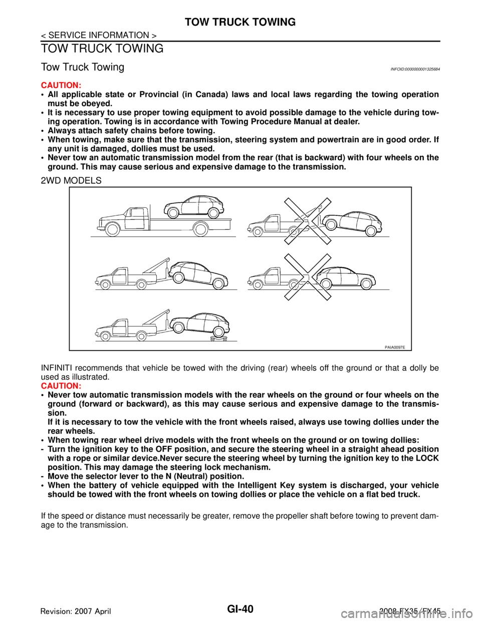
INFINITI recommends that vehicle be towed with the dr iving (rear) wheels off the ground or that a dolly be
used as illustrated.
CAUTION:
Never tow automatic transmission models with the r ear wheels on the ground or four wheels on the
ground (forward or backward), as this may cause serious and expensive damage to the transmis-
sion.
If it is necessary to tow the vehicle with the fron t wheels raised, always use towing dollies under the
rear wheels.
When towing rear wheel drive mo dels with the front wheels on the ground or on towing dollies:
- Turn the ignition key to the OFF position, and secure the steering wh eel in a straight ahead position
with a rope or similar device.Never secure the st eering wheel by turning the ignition key to the LOCK
position. This may damage the steering lock mechanism.
- Move the selector lever to the N (Neutral) position.
When the battery of vehicle equipped with the Intelligent Key system is discharged, your vehicle
should be towed with the front wh eels on towing dollies or place the vehicle on a flat bed truck.
If the speed or distance must necessarily be greater, re move the propeller shaft before towing to prevent dam-
age to the transmission.
PAIA0097E
3AA93ABC3ACD3AC03ACA3AC03AC63AC53A913A773A893A873A873A8E3A773A983AC73AC93AC03AC3
3A893A873A873A8F3A773A9D3AAF3A8A3A8C3A863A9D3AAF3A8B3A8C
Page 2936 of 3924
POWER WINDOW SYSTEMGW-23
< SERVICE INFORMATION >
C
DE
F
G H
J
K L
M A
B
GW
N
O P
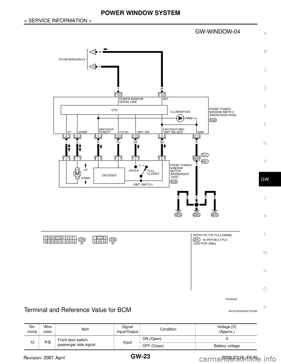
Terminal and Reference Value for BCMINFOID:0000000001327968
TIWH0054E
Te r -
minal Wire
color Item Signal
Input/Output Condition Voltage [V]
(Approx.)
12 P/B Front door switch
passenger side signal InputON (Open) 0
OFF (Close) Battery voltage
3AA93ABC3ACD3AC03ACA3AC03AC63AC53A913A773A893A873A873A8E3A773A983AC73AC93AC03AC3
3A893A873A873A8F3A773A9D3AAF3A8A3A8C3A863A9D3AAF3A8B3A8C