2008 INFINITI FX35 power seat
[x] Cancel search: power seatPage 3426 of 3924

PG-62
< SERVICE INFORMATION >
HARNESS
H/AIM LT Headlamp Aiming Control System
H/LAMP LT Headlamp
H/PHON AV Hands Free Telephone
HORN WW Horn
HSEAT SE Heated Seat
I/KEY BL Intelligent Key System
I/MIRR GW Inside Mirror (Auto Anti-Dazzling Mirror)
IATS EC Intake Air Temperature Sensor
ICC ACS Intelligent Cruise Control System
ICC/BS EC ICC Brake Switch
ICC/SW EC ICC Steering Switch
ICCBOF EC ICC Brake Switch
IGNSYS EC Ignition System
ILL LT Illumination
INF/D AV Vehicle Information and Integrated Switch System
INJECT EC Injector
IVCB1 EC Intake Valve Timing Control Solenoid Valve Bank 1
IVCB2 EC Intake Valve Timing Control Solenoid Valve Bank 2
IVCSB1 EC Intake Valve Timing Control Position Sensor Bank 1
IVCSB2 EC Intake Valve Timing Control Position Sensor Bank 2
IVTB1 EC Intake Valve Timing Control System (Bank 1)
IVTB2 EC Intake Valve Timing Control System (Bank 2)
KEYLES BL Remote Keyless Entry System
KS EC Knock Sensor
LDW DI Lane Departure Warning System
M/ANT AV Manual Antenna
MAFS EC Mass Air Flow Sensor
MAIN AT Main Power Supply and Ground Circuit
MAIN EC Main Power Supply and Ground Circuit
MES AV Mobile Entertainment System
METER DI Speedometer, Tachometer, Temp. and Fuel Gauges
MIL/DL EC MIL & Data Link Connector
MIRROR GW Power Door Mirror
MMSW AT Manual Mode Switch
NATS BL Nissan Anti-Theft System
NAVI AV Navigation System
NONDTC AT Non-Detective Items
O2H2B1 EC Heated Oxygen Sensor 2 Heater Bank 1
O2H2B2 EC Heated Oxygen Sensor 2 Heater Bank 2
O2S2B1 EC Heated Oxygen Sensor 2 Bank 1
O2S2B2 EC Heated Oxygen Sensor 2 Bank 2
P/SCKT WW Power Socket
PGC/V EC EVAP Canister Purge Volume Control Solenoid Valve
PHASE EC Camshaft Position Sensor (PHASE) Code Section Wiri
ng Diagram Name
3AA93ABC3ACD3AC03ACA3AC03AC63AC53A913A773A893A873A873A8E3A773A983AC73AC93AC03AC3
3A893A873A873A8F3A773A9D3AAF3A8A3A8C3A863A9D3AAF3A8B3A8C
Page 3427 of 3924
HARNESSPG-63
< SERVICE INFORMATION >
C
DE
F
G H
I
J
L
M A
B
PG
N
O P
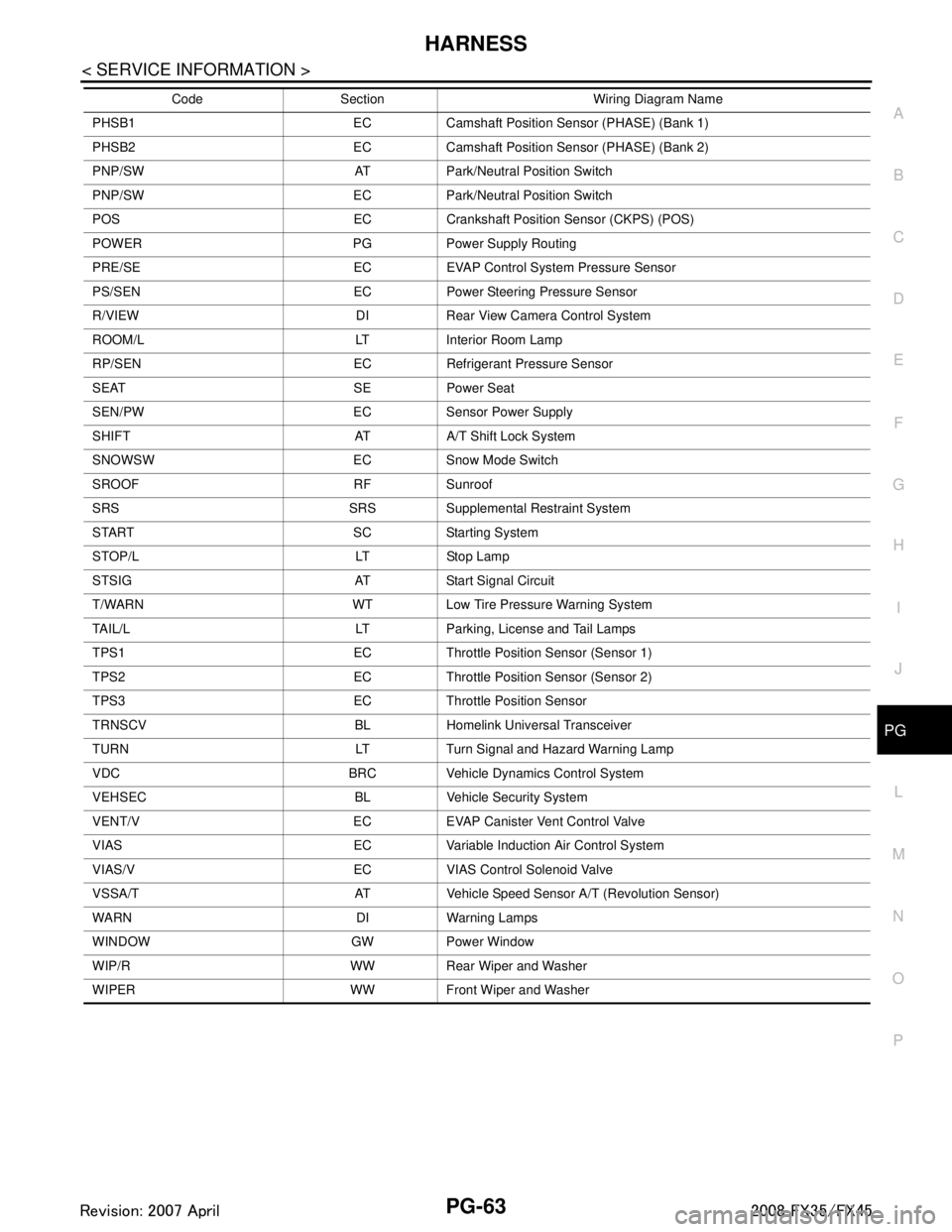
PHSB1 EC Camshaft Position Sensor (PHASE) (Bank 1)
PHSB2 EC Camshaft Position Sensor (PHASE) (Bank 2)
PNP/SW AT Park/Neutral Position Switch
PNP/SW EC Park/Neutral Position Switch
POS EC Crankshaft Position Sensor (CKPS) (POS)
POWER PG Power Supply Routing
PRE/SE EC EVAP Control System Pressure Sensor
PS/SEN EC Power Steering Pressure Sensor
R/VIEW DI Rear View Ca mera Control System
ROOM/L LT Interior Room Lamp
RP/SEN EC Refrigerant Pressure Sensor
SEAT SE Power Seat
SEN/PW EC Sensor Power Supply
SHIFT AT A/T Shift Lock System
SNOWSW EC Snow Mode Switch
SROOF RF Sunroof
SRS SRS Supplemental Restraint System
START SC Starting System
STOP/L LT Stop Lamp
STSIG AT Start Signal Circuit
T/WARN WT Low Tire Pressure Warning System
TAIL/L LT Parking, License and Tail Lamps
TPS1 EC Throttle Position Sensor (Sensor 1)
TPS2 EC Throttle Position Sensor (Sensor 2)
TPS3 EC Throttle Position Sensor
TRNSCV BL Homelink Universal Transceiver
TURN LT Turn Signal and Hazard Warning Lamp
VDC BRC Vehicle Dynamics Control System
VEHSEC BL Vehicle Security System
VENT/V EC EVAP Canister Vent Control Valve
VIAS EC Variable Induction Air Control System
VIAS/V EC VIAS Control Solenoid Valve
VSSA/T AT Vehicle Sp eed Sensor A/T (Revolution Sensor)
WARN DI Warning Lamps
WINDOW GW Power Window
WIP/R WW Rear Wiper and Washer
WIPER WW Front Wiper and Washer Code Section Wiring Diagram Name
3AA93ABC3ACD3AC03ACA3AC03AC63AC53A913A773A893A873A873A8E3A773A983AC73AC93AC03AC3
3A893A873A873A8F3A773A9D3AAF3A8A3A8C3A863A9D3AAF3A8B3A8C
Page 3456 of 3924

PS-1
STEERING
C
DE
F
H I
J
K L
M
SECTION PS
A
B
PS
N
O P
CONTENTS
POWER STEERING SYSTEM
SERVICE INFORMATION .. ..........................2
PRECAUTIONS .............................................. .....2
Precaution for Supplemental Restraint System
(SRS) "AIR BAG" and "SEAT BELT PRE-TEN-
SIONER" ............................................................. ......
2
Precaution Necessary for Steering Wheel Rota-
tion After Battery Disconnect .....................................
2
Precaution for Steering System ................................2
PREPARATION ...................................................4
Special Service Tool ........................................... ......4
Commercial Service Tool ..........................................5
NOISE, VIBRATION AND HARSHNESS
(NVH) TROUBLESHOOTING .............................
6
NVH Troubleshooting Chart ................................ ......6
POWER STEERING FLUID ................................7
Checking Fluid Level ........................................... ......7
Checking Fluid Leakage ............................................7
Air Bleeding Hydraulic System ..................................7
STEERING WHEEL .............................................9
On-Vehicle Inspection and Service ..................... ......9
Removal and Installation .........................................10
STEERING COLUMN .........................................12
Removal and Installation ..................................... ....12
Disassembly and Assembly .....................................14
POWER STEERING GEAR AND LINKAGE ....17
Removal and Installation .........................................17
Disassembly and Assembly .....................................19
POWER STEERING OIL PUMP .......................27
On-Vehicle Inspection and Service .........................27
Removal and Installation (VQ35DE Models) ...........28
Removal and Installation (VK45DE Models) ...........29
Disassembly and Assembly (VQ35DE Models) ......29
Disassembly and Assembly (VK45DE Models) .......32
HYDRAULIC LINE ............................................37
Component ..............................................................37
Removal and Installation .........................................39
SERVICE DATA AND SPECIFICATIONS
(SDS) .................................................................
41
Steering Wheel ........................................................41
Steering Angle .........................................................41
Steering Column ......................................................41
Steering Outer Socket and Inner Socket .................41
Steering Gear ..........................................................42
Oil Pump ..................................................................43
Steering Fluid ..........................................................43
3AA93ABC3ACD3AC03ACA3AC03AC63AC53A913A773A893A873A873A8E3A773A983AC73AC93AC03AC3
3A893A873A873A8F3A773A9D3AAF3A8A3A8C3A863A9D3AAF3A8B3A8C
Page 3457 of 3924
PS-2
< SERVICE INFORMATION >
PRECAUTIONS
SERVICE INFORMATION
PRECAUTIONS
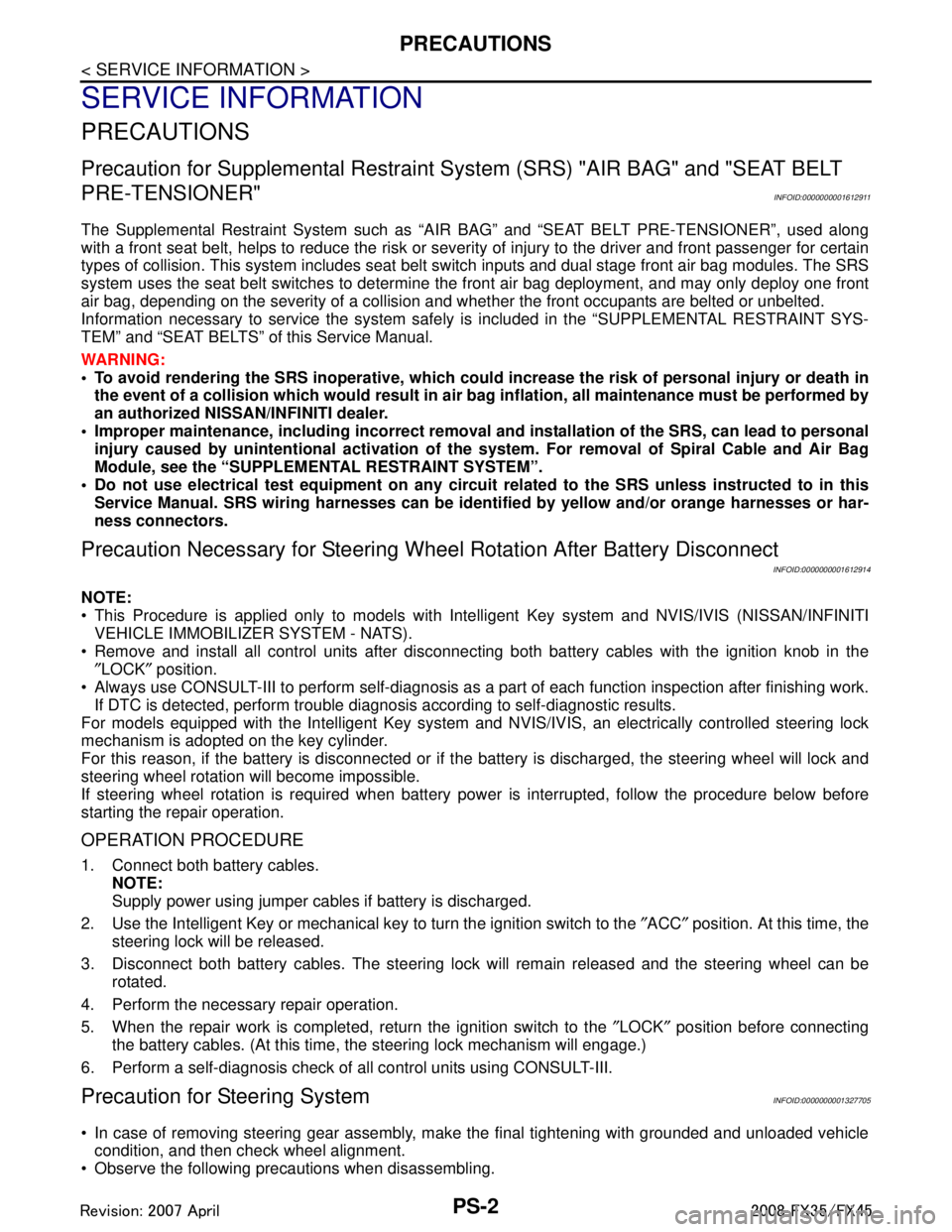
Precaution for Supplemental Restraint System (SRS) "AIR BAG" and "SEAT BELT
PRE-TENSIONER"
INFOID:0000000001612911
The Supplemental Restraint System such as “A IR BAG” and “SEAT BELT PRE-TENSIONER”, used along
with a front seat belt, helps to reduce the risk or severi ty of injury to the driver and front passenger for certain
types of collision. This system includes seat belt switch inputs and dual stage front air bag modules. The SRS
system uses the seat belt switches to determine the front air bag deployment, and may only deploy one front
air bag, depending on the severity of a collision and w hether the front occupants are belted or unbelted.
Information necessary to service the system safely is included in the “SUPPLEMENTAL RESTRAINT SYS-
TEM” and “SEAT BELTS” of this Service Manual.
WARNING:
• To avoid rendering the SRS inopera tive, which could increase the risk of personal injury or death in
the event of a collision which would result in air bag inflation, all maintenance must be performed by
an authorized NISS AN/INFINITI dealer.
Improper maintenance, including in correct removal and installation of the SRS, can lead to personal
injury caused by unintent ional activation of the system. For re moval of Spiral Cable and Air Bag
Module, see the “SUPPLEMEN TAL RESTRAINT SYSTEM”.
Do not use electrical test equipmen t on any circuit related to the SRS unless instructed to in this
Service Manual. SRS wiring harnesses can be identi fied by yellow and/or orange harnesses or har-
ness connectors.
Precaution Necessary for Steering W heel Rotation After Battery Disconnect
INFOID:0000000001612914
NOTE:
This Procedure is applied only to models with In telligent Key system and NVIS/IVIS (NISSAN/INFINITI
VEHICLE IMMOBILIZER SYSTEM - NATS).
Remove and install all control units after disconnecting both battery cables with the ignition knob in the ″LOCK ″ position.
Always use CONSULT-III to perform self-diagnosis as a part of each function inspection after finishing work.
If DTC is detected, perform trouble diagnosis according to self-diagnostic results.
For models equipped with the Intelligent Key system and NVIS /IVIS, an electrically controlled steering lock
mechanism is adopted on the key cylinder.
For this reason, if the battery is disconnected or if the battery is discharged, the steering wheel will lock and
steering wheel rotation will become impossible.
If steering wheel rotation is required when battery pow er is interrupted, follow the procedure below before
starting the repair operation.
OPERATION PROCEDURE
1. Connect both battery cables. NOTE:
Supply power using jumper cables if battery is discharged.
2. Use the Intelligent Key or mechanical key to turn the ignition switch to the ″ACC ″ position. At this time, the
steering lock will be released.
3. Disconnect both battery cables. The steering lock will remain released and the steering wheel can be
rotated.
4. Perform the necessary repair operation.
5. When the repair work is completed, return the ignition switch to the ″LOCK ″ position before connecting
the battery cables. (At this time, the steering lock mechanism will engage.)
6. Perform a self-diagnosis check of all control units using CONSULT-III.
Precaution for Steering SystemINFOID:0000000001327705
In case of removing steering gear assembly, make the final tightening with grounded and unloaded vehicle
condition, and then check wheel alignment.
Observe the following precautions when disassembling.
3AA93ABC3ACD3AC03ACA3AC03AC63AC53A913A773A893A873A873A8E3A773A983AC73AC93AC03AC3
3A893A873A873A8F3A773A9D3AAF3A8A3A8C3A863A9D3AAF3A8B3A8C
Page 3516 of 3924
RF-1
BODY
C
DE
F
G H
J
K L
M
SECTION RF
A
B
RF
N
O P
CONTENTS
ROOF
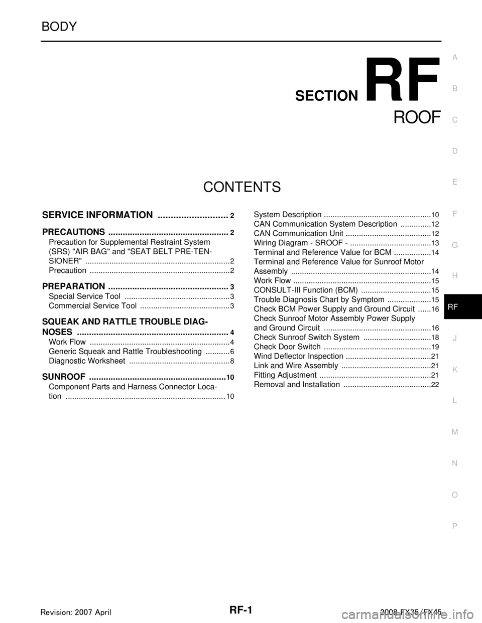
SERVICE INFORMATION .. ..........................2
PRECAUTIONS .............................................. .....2
Precaution for Supplemental Restraint System
(SRS) "AIR BAG" and "SEAT BELT PRE-TEN-
SIONER" ............................................................. ......
2
Precaution .................................................................2
PREPARATION ...................................................3
Special Service Tool ........................................... ......3
Commercial Service Tool ..........................................3
SQUEAK AND RATTLE TROUBLE DIAG-
NOSES ................................................................
4
Work Flow ........................................................... ......4
Generic Squeak and Rattle Troubleshooting ............6
Diagnostic Worksheet ...............................................8
SUNROOF ...................................................... ....10
Component Parts and Harness Connector Loca-
tion ...................................................................... ....
10
System Description .............................................. ....10
CAN Communication System Description ...............12
CAN Communication Unit ........................................12
Wiring Diagram - SROOF - ......................................13
Terminal and Reference Value for BCM ..................14
Terminal and Reference Value for Sunroof Motor
Assembly .................................................................
14
Work Flow ................................................................15
CONSULT-III Function (BCM) .................................15
Trouble Diagnosis Chart by Symptom .....................15
Check BCM Power Supply and Ground Circuit .......16
Check Sunroof Motor Assembly Power Supply
and Ground Circuit ..................................................
16
Check Sunroof Switch System ................................18
Check Door Switch ..................................................19
Wind Deflector Inspection ........................................21
Link and Wire Assembly ..........................................21
Fitting Adjustment ....................................................21
Removal and Installation .........................................22
3AA93ABC3ACD3AC03ACA3AC03AC63AC53A913A773A893A873A873A8E3A773A983AC73AC93AC03AC3
3A893A873A873A8F3A773A9D3AAF3A8A3A8C3A863A9D3AAF3A8B3A8C
Page 3596 of 3924
REAR LOWER LINK & COIL SPRINGRSU-15
< SERVICE INFORMATION >
C
DF
G H
I
J
K L
M A
B
RSU
N
O P
REAR LOWER LINK & COIL SPRING
Removal and InstallationINFOID:0000000001327560
REMOVAL
1. Remove tire with power tool.
2. Set jack under rear lower link.
3. Loosen fixing bolt and nut between rear lower link and suspension member, and then remove fixing bolt and nut between rear axle and rear lower link with power tool.
4. Slowly lower jack, then remove upper seat, co il spring and rubber seat from rear lower link.
5. Remove fixing bolt and nut between rear suspensi on member and rear lower link with power tool.
INSPECTION AFTER REMOVAL
Check rear lower link, bushing and coil spring for deformation, cracks, and damage. Replace rear lower link
and coil spring if necessary.
INSTALLATION
Refer to RSU-6, "Removal and Installation"for tightening torque. Install in the reverse order of removal.
CAUTION:
Refer to component parts location an d do not reuse non-reusable parts.
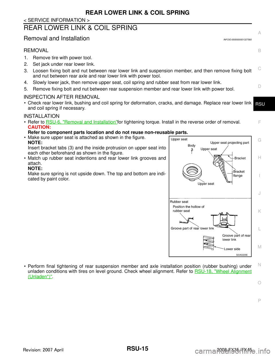
Make sure upper seat is attached as shown in the figure.
NOTE:
Insert bracket tabs (3) and the inside protrusion on upper seat into
each other beforehand as shown in the figure.
Match up rubber seat indentions and rear lower link grooves and
attach.
NOTE:
Make sure spring is not upside down. The top and bottom are indi-
cated by paint color.
Perform final tightening of rear suspension mem ber and axle installation position (rubber bushing) under
unladen conditions with tires on level ground. Check wheel alignment. Refer to RSU-18, "
Wheel Alignment
(Unladen*)".
SEIA0229E
3AA93ABC3ACD3AC03ACA3AC03AC63AC53A913A773A893A873A873A8E3A773A983AC73AC93AC03AC3
3A893A873A873A8F3A773A9D3AAF3A8A3A8C3A863A9D3AAF3A8B3A8C
Page 3640 of 3924
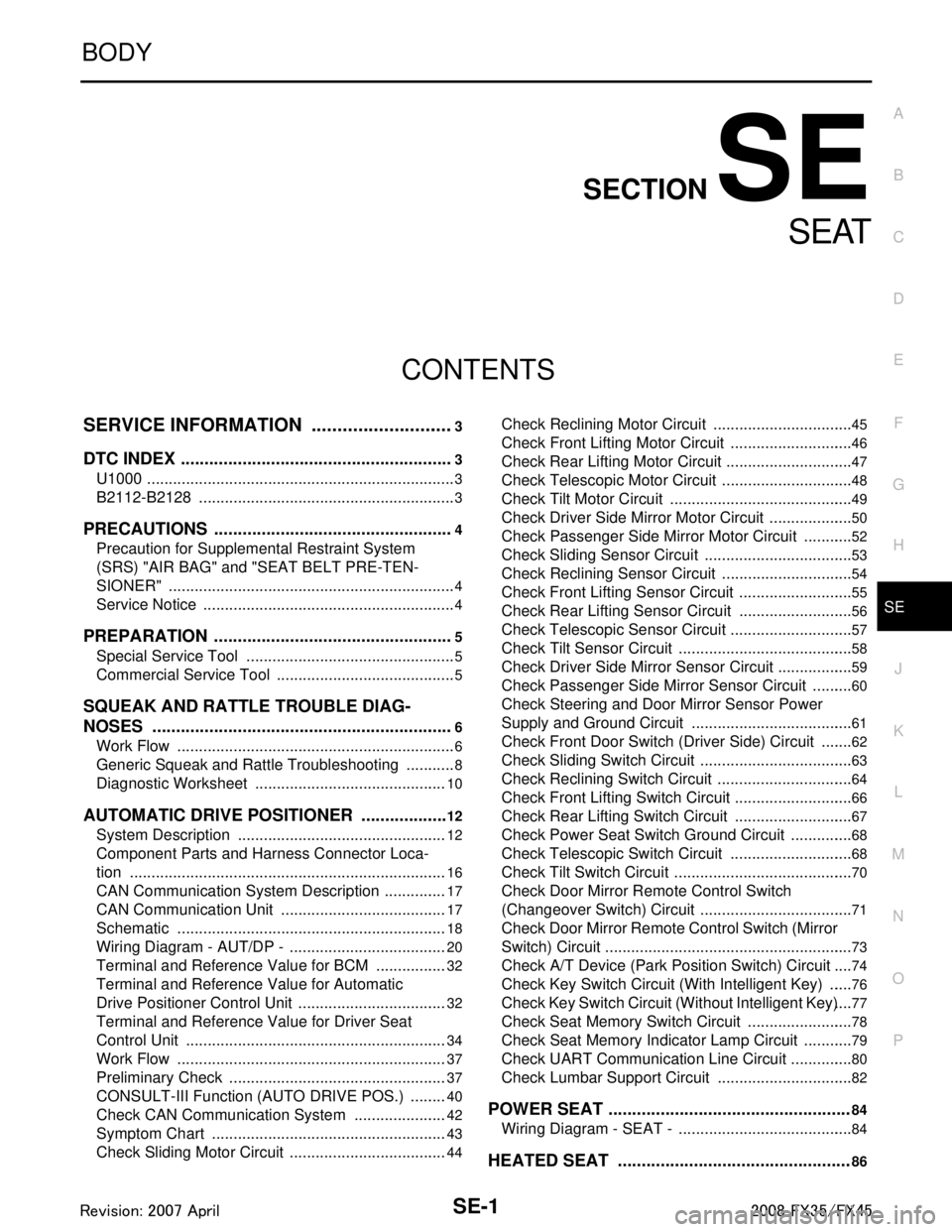
SE-1
BODY
C
DE
F
G H
J
K L
M
SECTION SE
A
B
SE
N
O P
CONTENTS
SEAT
SERVICE INFORMATION .. ..........................3
DTC INDEX ..................................................... .....3
U1000 .................................................................. ......3
B2112-B2128 ............................................................3
PRECAUTIONS ...................................................4
Precaution for Supplemental Restraint System
(SRS) "AIR BAG" and "SEAT BELT PRE-TEN-
SIONER" ............................................................. ......
4
Service Notice ...........................................................4
PREPARATION ...................................................5
Special Service Tool ........................................... ......5
Commercial Service Tool ..........................................5
SQUEAK AND RATTLE TROUBLE DIAG-
NOSES ................................................................
6
Work Flow ........................................................... ......6
Generic Squeak and Rattle Troubleshooting ............8
Diagnostic Worksheet .............................................10
AUTOMATIC DRIVE POSITIONER ...................12
System Description ............................................. ....12
Component Parts and Harness Connector Loca-
tion ..........................................................................
16
CAN Communication System Description ...............17
CAN Communication Unit .......................................17
Schematic ...............................................................18
Wiring Diagram - AUT/DP - .....................................20
Terminal and Reference Value for BCM .................32
Terminal and Reference Value for Automatic
Drive Positioner Control Unit ...................................
32
Terminal and Reference Value for Driver Seat
Control Unit .............................................................
34
Work Flow ...............................................................37
Preliminary Check ...................................................37
CONSULT-III Function (AUTO DRIVE POS.) .........40
Check CAN Communication System ......................42
Symptom Chart .......................................................43
Check Sliding Motor Circuit .....................................44
Check Reclining Motor Circuit ............................. ....45
Check Front Lifting Motor Circuit .............................46
Check Rear Lifting Motor Circuit ..............................47
Check Telescopic Motor Circuit ...............................48
Check Tilt Motor Circuit ...........................................49
Check Driver Side Mirror Motor Circuit ....................50
Check Passenger Side Mirror Motor Circuit ............52
Check Sliding Sensor Circuit ...................................53
Check Reclining Sensor Circuit ...............................54
Check Front Lifting Sensor Circuit ...........................55
Check Rear Lifting Sensor Circuit ...........................56
Check Telescopic Sensor Circuit .............................57
Check Tilt Sensor Circuit .........................................58
Check Driver Side Mirror Sensor Circuit ..................59
Check Passenger Side Mirror Sensor Circuit ..........60
Check Steering and Door Mirror Sensor Power
Supply and Ground Circuit .................................. ....
61
Check Front Door Switch (Driver Side) Circuit ........62
Check Sliding Switch Circuit ....................................63
Check Reclining Switch Circuit ................................64
Check Front Lifting Switch Circuit ............................66
Check Rear Lifting Switch Circuit ............................67
Check Power Seat Switch Ground Circuit ...............68
Check Telescopic Switch Circuit .............................68
Check Tilt Switch Circuit ..........................................70
Check Door Mirror Remote Control Switch
(Changeover Switch) Circuit ................................ ....
71
Check Door Mirror Remote Control Switch (Mirror
Switch) Circuit ...................................................... ....
73
Check A/T Device (Park Position Switch) Circuit ....74
Check Key Switch Circuit (With Intelligent Key) ......76
Check Key Switch Circuit (Without Intelligent Key) ....77
Check Seat Memory Switch Circuit ..................... ....78
Check Seat Memory Indicator Lamp Circuit ............79
Check UART Communication Line Circuit ...............80
Check Lumbar Support Circuit ............................ ....82
POWER SEAT ...................................................84
Wiring Diagram - SEAT - .........................................84
HEATED SEAT .................................................86
3AA93ABC3ACD3AC03ACA3AC03AC63AC53A913A773A893A873A873A8E3A773A983AC73AC93AC03AC3
3A893A873A873A8F3A773A9D3AAF3A8A3A8C3A863A9D3AAF3A8B3A8C
Page 3651 of 3924

SE-12
< SERVICE INFORMATION >
AUTOMATIC DRIVE POSITIONER
AUTOMATIC DRIVE POSITIONER
System DescriptionINFOID:0000000001328097
The system automatically moves the driver seat to facilitate entry/exit to/from the vehicle. The automatic
drive positioner control unit can also store the optimum driving positions (driver seat, steering wheel position
(tilt, telescopic) and door mirror position) for 2 people. If the driver is changes, one-touch operation allows
changing to the other driving position.
The settings (ON/OFF) of the automatic sliding s eat (Entry/Exiting operation) at entry/exit can be changed
as desired, using the display unit in the center of the instrument panel. The set content is transmitted by
CAN communication, from display contro l unit to driver seat control unit.
Using CONSULT-III, the seat slide and steering wheel amount at entry/exit setting can be changed.
MANUAL OPERATION
The driving position [seat position, steering wheel posit ion (tilt, telescopic) and door mirror position] can be
adjusted with the power seat switch or ADP steering switch or door mirror remote control switch.
NOTE:
The seat can be manually operated with the ignition switch OFF.
The door mirrors can be manually operated with the ignition switch turned ACC or ON.
AUTOMATIC OPERATION
NOTE:
Disconnecting the battery erases the stored memory.
After connecting the battery, insert the key into the ignition cylinder and turn the driver door switch ON (open) →OFF (close) →ON
(open), the Entry/ Exiting operation becomes possible.
After exiting operation is carried out, return operation can be operated.
NOTE:
During automatic operation, if the ignition switch is turned ON →START, the automatic operation is suspended. When the ignition switch
returns to ON, it resumes.
MEMORY STORING AND KEYFOB INTERLOCK STORING
Store the 2 driving positions and shifts to t he stored driving position with the memory switch.
Function Description
Memory switch operation The seat, steering and door mirror move to the stored driving position by pushing
memory switch (1 or 2).
Entry/Exiting function Exiting operation At exit, the seat moves backward and steering wheel moves forward/upward.
Entry operation
At entry, the seat and steering wheel returns from the exiting position to the previous
driving position.
keyfob interlock operation Perform memory operation, exiting operation and entry operation by pressing keyfob
unlock button.
Auto operation temporary stop
conditions. When ignition switch turned to START during memory switch operation and return opera-
tion, memory switch operation and entry operation is stopped.
Auto operation stop conditions. When the vehicle speed becomes 7 km/h (4 MPH) or higher.
When the setting switch, memory switch 1, or 2 are pressed.
When A/T selector lever is in any position other than P.
When the door mirror remote control switch is operated (when ignition switch turned to
ON or ACC).
When power seat switch turned ON.
When ADP steering switch turned ON (telescopic operation or tilt operation).
When door mirror operates (only memory switch operation).
When driver seat sliding Entry/Exiting setting is OFF (only entry/exiting operation).
When steering wheel tilt and telescopic Entry/Exiting setting is OFF (only entry/exiting op-
eration).
When the tilt and telescopic sensor malfunction is detected.
3AA93ABC3ACD3AC03ACA3AC03AC63AC53A913A773A893A873A873A8E3A773A983AC73AC93AC03AC3
3A893A873A873A8F3A773A9D3AAF3A8A3A8C3A863A9D3AAF3A8B3A8C