2008 INFINITI FX35 power seat
[x] Cancel search: power seatPage 3724 of 3924

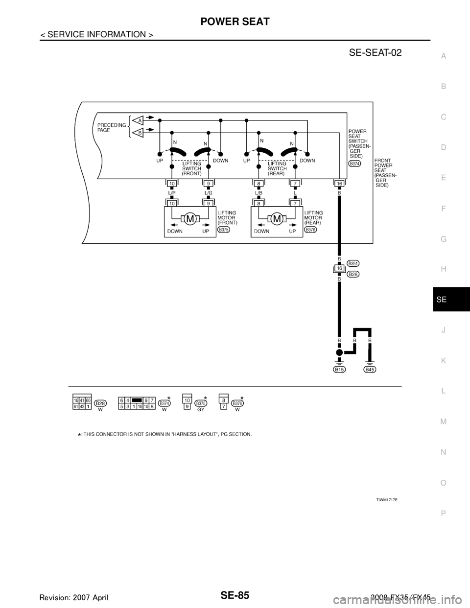
POWER SEATSE-85
< SERVICE INFORMATION >
C
DE
F
G H
J
K L
M A
B
SE
N
O P
TIWM1717E
3AA93ABC3ACD3AC03ACA3AC03AC63AC53A913A773A893A873A873A8E3A773A983AC73AC93AC03AC3
3A893A873A873A8F3A773A9D3AAF3A8A3A8C3A863A9D3AAF3A8B3A8C
Page 3729 of 3924

SE-90
< SERVICE INFORMATION >
FRONT SEAT
REMOVAL
When removing or installing the seat trim, carefully handle it to keep dirt out and avoid damage.
CAUTION:
Before removing the front seat, turn ignition switch OFF, disconnect both battery cables and wait at
least 3 minutes.
When checking the power seat circuit for continuity using a circuit tester, do not confuse its connec-
tor with the side air bag modul e connector. Such an error may cause the air bag to deploy.
Do not drop, tilt, or bump the side air bag module installing in the seat. Always handle it with care.
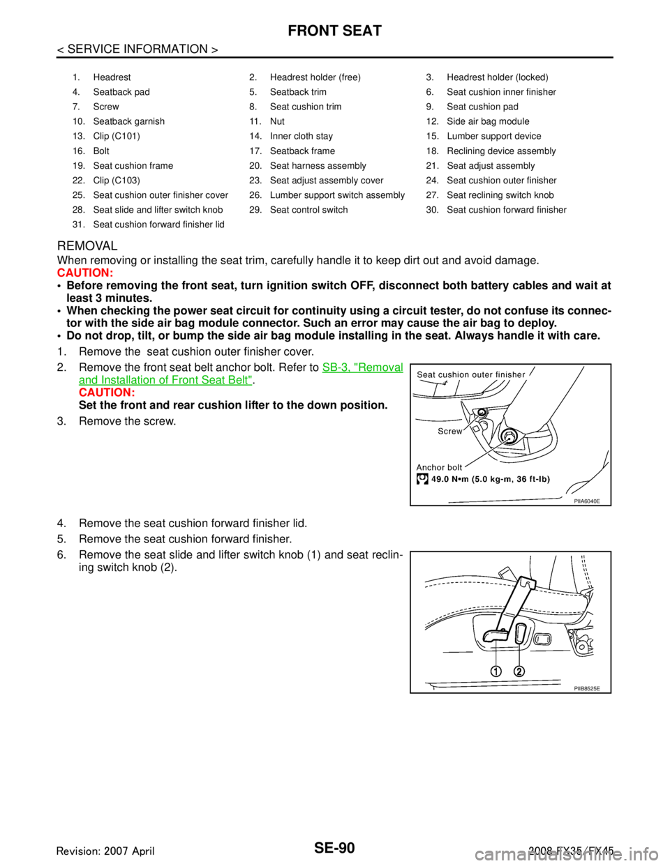
1. Remove the seat cushion outer finisher cover.
2. Remove the front seat belt anchor bolt. Refer to SB-3, "
Removal
and Installation of Front Seat Belt".
CAUTION:
Set the front and rear cushion lifter to the down position.
3. Remove the screw.
4. Remove the seat cushion forward finisher lid.
5. Remove the seat cushion forward finisher.
6. Remove the seat slide and lifter switch knob (1) and seat reclin- ing switch knob (2).
1. Headrest 2. Headrest holder (free) 3. Headrest holder (locked)
4. Seatback pad 5. Seatback trim 6. Seat cushion inner finisher
7. Screw 8. Seat cushion trim 9. Seat cushion pad
10. Seatback garnish 11. Nut 12. Side air bag module
13. Clip (C101) 14. Inner cloth stay 15. Lumber support device
16. Bolt 17. Seatback frame 18. Reclining device assembly
19. Seat cushion frame 20. Seat harness assembly 21. Seat adjust assembly
22. Clip (C103) 23. Seat adjust assembly cover 24. Seat cushion outer finisher
25. Seat cushion outer finisher cover 26. Lumber support switch assembly 27. Seat reclining switch knob
28. Seat slide and lifter switch knob 29. Seat control switch 30. Seat cushion forward finisher
31. Seat cushion forward finisher lid
PIIA6040E
PIIB8525E
3AA93ABC3ACD3AC03ACA3AC03AC63AC53A913A773A893A873A873A8E3A773A983AC73AC93AC03AC3
3A893A873A873A8F3A773A9D3AAF3A8A3A8C3A863A9D3AAF3A8B3A8C
Page 3730 of 3924

FRONT SEATSE-91
< SERVICE INFORMATION >
C
DE
F
G H
J
K L
M A
B
SE
N
O P
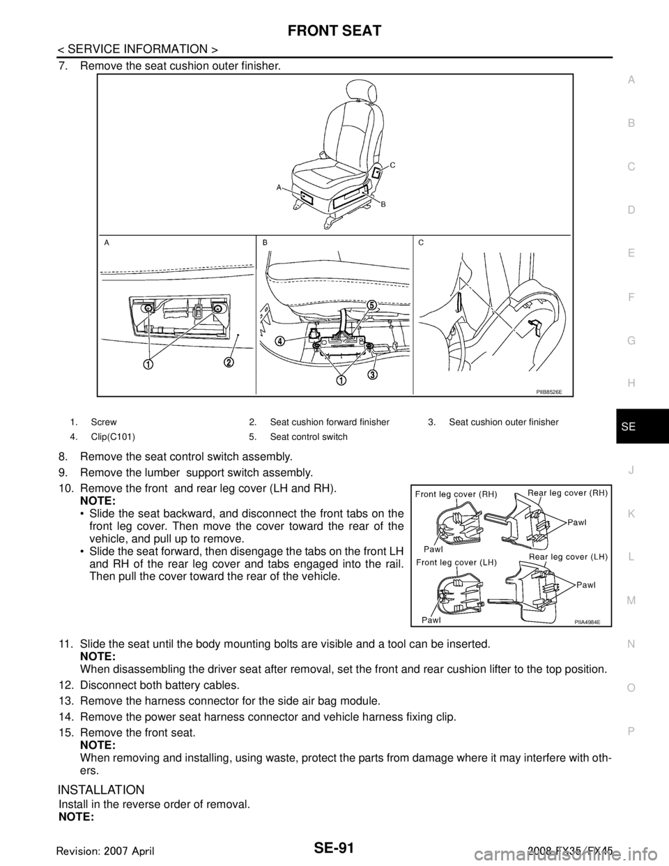
7. Remove the seat cushion outer finisher.
8. Remove the seat control switch assembly.
9. Remove the lumber support switch assembly.
10. Remove the front and rear leg cover (LH and RH). NOTE:
Slide the seat backward, and disconnect the front tabs on the
front leg cover. Then move the cover toward the rear of the
vehicle, and pull up to remove.
Slide the seat forward, then disengage the tabs on the front LH and RH of the rear leg cover and tabs engaged into the rail.
Then pull the cover toward the rear of the vehicle.
11. Slide the seat until the body mounting bolts are visible and a tool can be inserted. NOTE:
When disassembling the driver seat after removal, set the front and rear cushion lifter to the top position.
12. Disconnect both battery cables.
13. Remove the harness connector for the side air bag module.
14. Remove the power seat harness connector and vehicle harness fixing clip.
15. Remove the front seat. NOTE:
When removing and installing, using waste, protect t he parts from damage where it may interfere with oth-
ers.
INSTALLATION
Install in the reverse order of removal.
NOTE:
PIIB8526E
1. Screw 2. Seat cushion forward finisher 3. Seat cushion outer finisher
4. Clip(C101) 5. Seat control switch
PIIA4984E
3AA93ABC3ACD3AC03ACA3AC03AC63AC53A913A773A893A873A873A8E3A773A983AC73AC93AC03AC3
3A893A873A873A8F3A773A9D3AAF3A8A3A8C3A863A9D3AAF3A8B3A8C
Page 3761 of 3924
![INFINITI FX35 2008 Service Manual
SRS-24
< SERVICE INFORMATION >
TROUBLE DIAGNOSIS
Trouble Diagnosis with CONSULT-III
INFOID:0000000001524168
DIAGNOSTIC PROCEDURE
DTC No. Index (“SELF-DIAG [ CURRENT]” “SELF-DIAG [PAST]” or INFINITI FX35 2008 Service Manual
SRS-24
< SERVICE INFORMATION >
TROUBLE DIAGNOSIS
Trouble Diagnosis with CONSULT-III
INFOID:0000000001524168
DIAGNOSTIC PROCEDURE
DTC No. Index (“SELF-DIAG [ CURRENT]” “SELF-DIAG [PAST]” or](/manual-img/42/57017/w960_57017-3760.png)
SRS-24
< SERVICE INFORMATION >
TROUBLE DIAGNOSIS
Trouble Diagnosis with CONSULT-III
INFOID:0000000001524168
DIAGNOSTIC PROCEDURE
DTC No. Index (“SELF-DIAG [ CURRENT]” “SELF-DIAG [PAST]” or TROUBLE DIAG RECORD)
Air bag is deployed.
Seat belt pre-tensioner is deployed. Go to
SRS-47, "For Frontal Colli-
sion" or SRS-48, "For Side Collision"
Diagnosis sensor unit is malfunction-
ing.
Air bag power supply circuit is mal-
functioning.
SRS air bag warning lamp circuit is malfunctioning. Go to
SRS-32, "
Trouble Diagnosis:
"AIR BAG" Warning Lamp Does Not
Turn OFF".
Diagnosis sensor unit is malfunction- ing.
Air bag warning lamp circuit is mal-
functioning. Go to
SRS-32, "
Trouble Diagnosis:
"AIR BAG" Warning Lamp Does Not
Turn ON".
“AIR BAG” warning lamp operation — User mode
—
SRS condition Reference item
SHIA0013E
SHIA0014E
Diagnostic mode Description
SELF-DIAG RESULT The self-d iagnosis result is Displayed. (SELF-DIAG [ CURRENT], [PAST], [RECORD])
ECU DISCRIMINATED No. The parts number of diagnosis sensor units displayed.
Diagnostic item Explanation Repair order
“Recheck SRS at each replacement”
NO DTC IS DETECT-
ED. When malfunction is in-
dicated by the “AIR
BAG” warning lamp in
User mode. Low battery voltage (Less than 9V)
Self-diagnostic result “SELF-DIAG
[PAST]” (previously stored in the
memory) might not be erased after re-
pair.
Intermittent malfunction has been de- tected in the past. Go to
SRS-21, "
CONSULT-III Func-
tion".
No malfunction is detected. —
DIAGNOSIS SENSOR
UNIT (CONTROL UNIT)
[B1001-B1015] Diagnosis sensor is out of order. Replace diagnosis sensor unit.
(ACU)
3AA93ABC3ACD3AC03ACA3AC03AC63AC53A913A773A893A873A873A8E3A773A983AC73AC93AC03AC3
3A893A873A873A8F3A773A9D3AAF3A8A3A8C3A863A9D3AAF3A8B3A8C
Page 3763 of 3924
![INFINITI FX35 2008 Service Manual
SRS-26
< SERVICE INFORMATION >
TROUBLE DIAGNOSIS
DRIVER AIR BAG
MODULE
[OPEN]
[B1049] [B1054] Driver air bag module circuit is open (including the spiral cable). 1. Visually check the wiring harnes INFINITI FX35 2008 Service Manual
SRS-26
< SERVICE INFORMATION >
TROUBLE DIAGNOSIS
DRIVER AIR BAG
MODULE
[OPEN]
[B1049] [B1054] Driver air bag module circuit is open (including the spiral cable). 1. Visually check the wiring harnes](/manual-img/42/57017/w960_57017-3762.png)
SRS-26
< SERVICE INFORMATION >
TROUBLE DIAGNOSIS
DRIVER AIR BAG
MODULE
[OPEN]
[B1049] [B1054] Driver air bag module circuit is open (including the spiral cable). 1. Visually check the wiring harness
connection.
2. Replace the harness if it has visi- ble damage.
3. Replace driver air bag module.
4. Replace spiral cable.
5. Replace diagnosis sensor unit (ACU).
DRIVER AIR BAG
MODULE
[VB-SHORT]
[B1050] [B1055] Driver air bag module circuit is shorted to a power supply circuit
(including the spiral cable).
DRIVER AIR BAG
MODULE
[GND-SHORT]
[B1051] [B1056] Driver air bag module circuit is shorted to ground (including the
spiral cable).
DRIVER AIR BAG
MODULE
[SHORT]
[B1052] [B1057] Driver air bag module circuit is shorted between lines.
DIAGNOSIS SENSOR
UNIT (CONTROL UNIT)
[B1058-B1063] Diagnosis sensor is out of order. Replace diagnosis sensor unit.
(ACU)
ASSIST A/B MODULE
[OPEN]
[B1065] [B1070] Front passenger air bag module circuit is open. 1. Visually check the wiring harness
connection.
2. Replace the harness if it has visi- ble damage.
3. Replace front passenger air bag
module.
4. Replace diagnosis sensor unit (ACU).
ASSIST A/B MODULE
[VB-SHORT]
[B1066] [B1071]
Front passenger air bag module circuit is shorted to a power sup-
ply circuit.
ASSIST A/B MODULE
[GND-SHORT]
[B1067] [B1072] Front passenger air bag module circuit is shorted to ground.
ASSIST A/B MODULE
[SHORT]
[B1068] [B1073] Front passenger air bag module circuit is shorted between lines.
DIAGNOSIS SENSOR
UNIT (CONTROL UNIT)
[B1074-B1079] Diagnosis sensor is out of order. Replace diagnosis sensor unit.
(ACU)
PRE-TEN FRONT RH
[OPEN]
[B1081] Front RH pre-tensioner circuit is open. 1. Visually check the wiring harness
connections.
2. Replace the harness if it has visi- ble damage.
3. Replace front RH seat belt.
4. Replace diagnosis sensor unit
(ACU).
PRE-TEN FRONT RH
[VB-SHORT]
[B1082]
Front RH pre-tensioner circuit is shorted to a power supply cir-
cuit.
PRE-TEN FRONT RH
[GND-SHORT]
[B1083] Front RH pre-tensioner circuit is shorted to ground.
PRE-TEN FRONT RH
[SHORT]
[B1084] Front RH pre-tensioner circuit is shorted between lines.
Diagnostic item Explanation
Repair order
“Recheck SRS at each replacement”
3AA93ABC3ACD3AC03ACA3AC03AC63AC53A913A773A893A873A873A8E3A773A983AC73AC93AC03AC3
3A893A873A873A8F3A773A9D3AAF3A8A3A8C3A863A9D3AAF3A8B3A8C
Page 3764 of 3924
![INFINITI FX35 2008 Service Manual
TROUBLE DIAGNOSISSRS-27
< SERVICE INFORMATION >
C
DE
F
G
I
J
K L
M A
B
SRS
N
O P
PRE-TEN FRONT LH
[OPEN]
[B1086] Front LH pre-tensioner circuit is open. 1. Visually check the wiring harness
conne INFINITI FX35 2008 Service Manual
TROUBLE DIAGNOSISSRS-27
< SERVICE INFORMATION >
C
DE
F
G
I
J
K L
M A
B
SRS
N
O P
PRE-TEN FRONT LH
[OPEN]
[B1086] Front LH pre-tensioner circuit is open. 1. Visually check the wiring harness
conne](/manual-img/42/57017/w960_57017-3763.png)
TROUBLE DIAGNOSISSRS-27
< SERVICE INFORMATION >
C
DE
F
G
I
J
K L
M A
B
SRS
N
O P
PRE-TEN FRONT LH
[OPEN]
[B1086] Front LH pre-tensioner circuit is open. 1. Visually check the wiring harness
connections.
2. Replace the harness if it has visi- ble damage.
3. Replace the front LH seat belt.
4. Replace the diagnosis sensor unit.
5. Replace the related harness.
PRE-TEN FRONT LH
[VB-SHORT]
[B1087]
Front LH pre-tensioner circuit is shorted to a power supply cir-
cuit.
PRE-TEN FRONT LH
[GND-SHORT]
[B1088] Front LH pre-tensioner circuit is shorted to ground.
PRE-TEN FRONT LH
[SHORT]
[B1089] Front LH pre-tensioner circuit is shorted between lines.
DIAGNOSIS SENSOR
UNIT (CONTROL UNIT)
[ B 11 0 6 - B 1111 ] Diagnosis sensor is out of order. Replace diagnosis sensor unit
(ACU).
SATELLITE SENS RH
[UNIT FAIL]
[ B 111 3 ] [ B 111 4 ]
SATELLITE SENS RH
[COMM FAIL]
[ B 111 5 ] RH side air bag (Satellite) sensor 1. Visually check the wiring harness
connection.
2. Replace the harness if it has visi-
ble damage.
3. Replace RH side air bag (Satel- lite) sensor.
4. Replace diagnosis sensor unit (ACU).
SATELLITE SENS LH
[UNIT FAIL]
[ B 111 8 ] [ B 111 9 ]
SATELLITE SENS LH
[COMM FAIL]
[B1120] LH side air bag (Satellite) sensor 1. Visually check the wiring harness
connection.
2. Replace the harness if it has visi- ble damage.
3. Replace LH side air bag (Satel-
lite) sensor.
4. Replace diagnosis sensor unit (ACU).
DIAGNOSIS SENSOR
UNIT (CONTROL UNIT)
[ B 11 2 2 - B 11 2 7 ] Diagnosis sensor is out of order. Replace diagnosis sensor unit
(ACU).
SIDE MODULE RH
[OPEN]
[B1129] Front RH side air bag module circuit is open. 1. Visually check the wiring harness
connection.
2. Replace the harness if it has visi- ble damage.
3. Replace front RH side air bag module.
4. Replace diagnosis sensor unit (ACU).
SIDE MODULE RH
[VB-SHORT]
[B1130]
Front RH side air bag module circuit is shorted to a power supply
circuit.
SIDE MODULE RH
[GND-SHORT]
[B1131] Front RH side air bag module circuit is shorted to ground.
SIDE MODULE RH
[SHORT]
[B1132] Front RH side air bag module circuit is shorted between lines.
Diagnostic item Explanation
Repair order
“Recheck SRS at each replacement”
3AA93ABC3ACD3AC03ACA3AC03AC63AC53A913A773A893A873A873A8E3A773A983AC73AC93AC03AC3
3A893A873A873A8F3A773A9D3AAF3A8A3A8C3A863A9D3AAF3A8B3A8C
Page 3765 of 3924

SRS-28
< SERVICE INFORMATION >
TROUBLE DIAGNOSIS
NOTE:
Follow the procedures in numerical order when repairing malfunctioning parts. Confirm whether malfunction is
eliminated using air bag warning lamp or CONSULT-III eac h time repair is finished. If malfunction is still
observed, proceed to the next step. When malfunction is eliminated, further repair work is not required.
Trouble Diagnosis without CONSULT-IIIINFOID:0000000001524169
DIAGNOSTIC PROCEDURE
SIDE MODULE LH
[OPEN]
[B1134] Front LH side air bag module circuit is open. 1. Visually check the wiring harness
connection.
2. Replace the harness if it has visi- ble damage.
3. Replace front LH side air bag module.
4. Replace diagnosis sensor unit
(ACU).
SIDE MODULE LH
[VB-SHORT]
[B1135]
Front LH side air bag module circuit is shorted to a power supply
circuit.
SIDE MODULE LH
[GND-SHORT]
[B1136] Front LH side air bag module circuit is shorted to ground.
SIDE MODULE LH
[SHORT]
[B1137] Front LH side air bag module circuit is shorted between lines.
DIAGNOSIS SENSOR
UNIT (CONTROL UNIT)
[ B 11 3 8 - B 11 4 3 ] Diagnosis sensor is out of order. Replace diagnosis sensor unit
(ACU).
CURTAIN MODULE RH
[OPEN]
[B1145] RH side curtain air bag module circuit is open. 1. Visually check the wiring harness
connection.
2. Replace the harness if it has visi-
ble damage.
3. Replace RH side curtain air bag module.
4. Replace diagnosis sensor unit (ACU).
CURTAIN MODULE RH
[VB-SHORT]
[B1146]
RH side curtain air bag module circuit is shorted to a power sup-
ply circuit.
CURTAIN MODULE RH
[GND-SHORT]
[B1147] RH side curtain air bag module circuit is shorted to ground.
CURTAIN MODULE RH
[SHORT]
[B1148] RH side curtain air bag module circuit is shorted between lines.
CURTAIN MODULE LH
[OPEN]
[B1150] LH side curtain air bag module circuit is open. 1. Visually check the wiring harness
connection.
2. Replace the harness if it has visi- ble damage.
3. Replace LH side curtain air bag module.
4. Replace diagnosis sensor unit
(ACU).
CURTAIN MODULE LH
[VB-SHORT]
[B1151]
LH side curtain air bag module circuit is shorted to a power sup-
ply circuit.
CURTAIN MODULE LH
[GND-SHORT]
[B1152] LH side curtain air bag module circuit is shorted to ground.
CURTAIN MODULE LH
[SHORT]
[B1153] LH side curtain air bag module circuit is shorted between lines.
DIAGNOSIS SENSOR
UNIT (CONTROL UNIT)
[B1202-B1207] Diagnosis sensor is out of order. Replace diagnosis sensor unit.
FRONTAL COLLISION-
DETECTION
[B1209] Seat belt pre-tensioner and front air bag are deployed. Go to
SRS-47, "
For Frontal Colli-
sion".
SIDE COLLISION DE-
TECTION
[B1210] Side and curtain air bag is deployed. Go to
SRS-48, "
For Side Collision".
Diagnostic item Explanation
Repair order
“Recheck SRS at each replacement”
3AA93ABC3ACD3AC03ACA3AC03AC63AC53A913A773A893A873A873A8E3A773A983AC73AC93AC03AC3
3A893A873A873A8F3A773A9D3AAF3A8A3A8C3A863A9D3AAF3A8B3A8C
Page 3787 of 3924

TF-1
DRIVELINE/AXLE
CEF
G H
I
J
K L
M
SECTION TF
A
B
TF
N
O P
CONTENTS
TRANSFER
SERVICE INFORMATION .. ..........................3
DTC INDEX ..................................................... .....3
C1201-C1210, U1000 ......................................... ......3
PRECAUTIONS ...................................................4
Precaution for Supplemental Restraint System
(SRS) "AIR BAG" and "SEAT BELT PRE-TEN-
SIONER" ............................................................. ......
4
Precaution .................................................................4
Service Notice or Precaution .....................................5
PREPARATION ...................................................6
Special Service Tool ........................................... ......6
Commercial Service Tool ..........................................7
NOISE, VIBRATION AND HARSHNESS
(NVH) TROUBLESHOOTING .............................
9
NVH Troubleshooting Chart ................................ ......9
TRANSFER FLUID .............................................10
Replacement ....................................................... ....10
Inspection ................................................................10
AWD SYSTEM ................................................ ....11
Power Transfer Diagram ..................................... ....11
System Description .................................................11
Schematic ...............................................................13
CAN Communication ...............................................13
TROUBLE DIAGNOSIS .....................................14
Fail-Safe Function ............................................... ....14
How to Perform Trouble Diagnosis .........................14
Location of Electrical Parts ......................................15
Circuit Diagram .......................................................16
Wiring Diagram - AWD - ..........................................17
Trouble Diagnosis Chart by Symptom ....................20
AWD Control Unit Input/Output Signal Reference
Value ................................................................... ....
20
CONSULT-III Function (ALL MODE AWD/4WD) ....21
TROUBLE DIAGNOSIS FOR SYSTEM .............24
DTC C1201 CONTROLLER FAILURE ................ ....24
DTC C1203 ABS SYSTEM ......................................24
DTC C1204 4WD SOLENOID ............................. ....25
DTC C1205 4WD ACTUATOR RLY ........................27
DTC C1210 ENGINE SIGNAL 1 ..............................28
DTC U1000 CAN COMM CIRCUIT .........................28
Power Supply Circuit for AWD Control Unit .............28
TROUBLE DIAGNOSIS FOR SYMPTOMS ......30
AWD Warning Lamp Does Not Turn ON When the
Ignition Switch Is Turned to ON ...............................
30
AWD Warning Lamp Does Not Turn OFF Several
Seconds after Engine Started ..................................
30
Heavy Tight-Corner Braking Symptom Occurs
When the Vehicle Is Driven and the Steering
Wheel Is Turned Fully to Either Side after the En-
gine Is Started .........................................................
32
Vehicle Does Not Enter AWD Mode Even Though
AWD Warning Lamp Turned to OFF .......................
33
While Driving, AWD Warning Lamp Flashes Rap-
idly (When Flashing in Approx. 1 Minute and Then
Turning OFF) ....................................................... ....
33
While Driving, AWD Warning Lamp Flashes Slow-
ly (When Continuing to Flash until Turning Ignition
Switch OFF) .............................................................
33
AWD CONTROL UNIT ......................................35
Removal and Installation .........................................35
FRONT OIL SEAL .............................................36
Removal and Installation .........................................36
REAR OIL SEAL ...............................................37
Removal and Installation .........................................37
AIR BREATHER HOSE ....................................39
Removal and Installation .........................................39
TRANSFER ASSEMBLY ..................................40
Removal and Installation .........................................40
Disassembly and Assembly .....................................40
3AA93ABC3ACD3AC03ACA3AC03AC63AC53A913A773A893A873A873A8E3A773A983AC73AC93AC03AC3
3A893A873A873A8F3A773A9D3AAF3A8A3A8C3A863A9D3AAF3A8B3A8C