2008 INFINITI FX35 power seat
[x] Cancel search: power seatPage 2914 of 3924
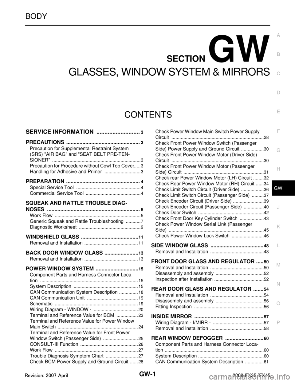
GW-1
BODY
C
DE
F
G H
J
K L
M
SECTION GW
A
B
GW
N
O P
CONTENTS
GLASSES, WINDOW SYSTEM & MIRRORS
SERVICE INFORMATION .. ..........................3
PRECAUTIONS .............................................. .....3
Precaution for Supplemental Restraint System
(SRS) "AIR BAG" and "SEAT BELT PRE-TEN-
SIONER" ............................................................. ......
3
Precaution for Procedure without Cowl Top Cover ......3
Handling for Adhesive and Primer ............................3
PREPARATION ...................................................4
Special Service Tool ........................................... ......4
Commercial Service Tool ..........................................4
SQUEAK AND RATTLE TROUBLE DIAG-
NOSES ................................................................
5
Work Flow ........................................................... ......5
Generic Squeak and Rattle Troubleshooting ............7
Diagnostic Worksheet ...............................................9
WINDSHIELD GLASS ........................................11
Removal and Installation ..................................... ....11
BACK DOOR WINDOW GLASS ........................13
Removal and Installation ..................................... ....13
POWER WINDOW SYSTEM ..............................15
Component Parts and Harness Connector Loca-
tion ...................................................................... ....
15
System Description .................................................15
CAN Communication System Description ...............18
CAN Communication Unit .......................................19
Schematic ...............................................................19
Wiring Diagram - WINDOW - ..................................20
Terminal and Reference Value for BCM .................23
Terminal and Reference Value for Power Window
Main Switch .............................................................
24
Terminal and Reference Value for Front Power
Window Switch (Passenger Side) ...........................
25
CONSULT-III Function ............................................26
Work Flow ...............................................................27
Trouble Diagnosis Symptom Chart .........................27
Check BCM Power Supply and Ground Circuit .......28
Check Power Window Main Switch Power Supply
Circuit .................................................................. ....
28
Check Front Power Window Switch (Passenger
Side) Power Supply and Ground Circuit ..................
30
Check Front Power Window Motor (Driver Side)
Circuit ......................................................................
30
Check Front Power Window Motor (Passenger
Side) Circuit .............................................................
31
Check rear Power Window Motor (LH) Circuit .........32
Check Rear Power Window Motor (RH) Circuit .......34
Check Limit Switch Circuit (Driver Side) .............. ....36
Check Limit Switch Circuit (Passenger Side) ..........37
Check Encoder Circuit (Driver Side) ........................39
Check Encoder Circuit (Passenger Side) ................40
Check Door Switch ..................................................42
Check Front Door Key Cylinder Switch ...................43
Check Power Window Serial Link (Passenger
Side) ........................................................................
45
Check Power Window Lock Switch .........................46
SIDE WINDOW GLASS ....................................48
Removal and Installation .........................................48
FRONT DOOR GLASS AND REGULATOR .....50
Removal and Installation .........................................50
Disassembly and assembly .....................................52
Inspection after Installation ......................................52
REAR DOOR GLASS AND REGULATOR .......54
Removal and Installation .........................................54
Disassembly and assembly .....................................56
Fitting Inspection .....................................................56
INSIDE MIRROR ...............................................57
Wiring Diagram - I/MIRR - .......................................57
Removal and Installation .........................................58
REAR WINDOW DEFOGGER ..........................60
Component Parts and Harness Connector Loca-
tion ...........................................................................
60
System Description ..................................................60
CAN Communication System Description ...............61
3AA93ABC3ACD3AC03ACA3AC03AC63AC53A913A773A893A873A873A8E3A773A983AC73AC93AC03AC3
3A893A873A873A8F3A773A9D3AAF3A8A3A8C3A863A9D3AAF3A8B3A8C
Page 3092 of 3924
![INFINITI FX35 2008 Service Manual
LAN-72
< SERVICE INFORMATION >[CAN]
TROUBLE DIAGNOSIS
OK or NG
OK >> Present error: Check the following items again.
- Decision of CAN system type.
- Not received CONSULT-III data [SELF-DIAG RESUL INFINITI FX35 2008 Service Manual
LAN-72
< SERVICE INFORMATION >[CAN]
TROUBLE DIAGNOSIS
OK or NG
OK >> Present error: Check the following items again.
- Decision of CAN system type.
- Not received CONSULT-III data [SELF-DIAG RESUL](/manual-img/42/57017/w960_57017-3091.png)
LAN-72
< SERVICE INFORMATION >[CAN]
TROUBLE DIAGNOSIS
OK or NG
OK >> Present error: Check the following items again.
- Decision of CAN system type.
- Not received CONSULT-III data [SELF-DIAG RESULTS, CAN DIAG SUPPORT MNTR (“ECU
list” included)].
- Not copied from on-board diagnosis.
- Procedure for detecting root cause.
Past error: Error was detected in the main li ne between the ABS actuator and electric unit (con-
trol unit) and the driver seat control unit.
NG >> Repair the main line between the harness connectors B5 and B8.
ECM Branch Line CircuitINFOID:0000000001328654
INSPECTION PROCEDURE
1.CHECK CONNECTOR
1. Turn the ignition switch OFF.
2. Disconnect the battery cable from the negative terminal.
3. Check the terminals and connectors of the ECM for damage, bend and loose connection (unit side and connector side).
OK or NG
OK >> GO TO 2.
NG >> Repair the terminal and connector.
2.CHECK HARNESS FOR OPEN CIRCUIT
1. Disconnect the connector of ECM.
2. Check the resistance between the ECM harness connector terminals.
OK or NG
OK >> GO TO 3.
NG >> Repair the ECM branch line.
3.CHECK POWER SUPPLY AND GROUND CIRCUIT
Check the power supply and the ground circuit of the ECM. Refer to EC-141, "
Diagnosis Procedure"
(VQ35DE), EC-719, "Diagnosis Procedure" (VK45DE).
OK or NG
OK >> Present error: Replace the ECM. Refer to EC-100, "Engine Control Component Parts Loca-
tion"(VQ35DE), EC-677, "Engine Control Component Parts Location" (VK45DE).
Past error: Error was detected in the ECM branch line.
NG >> Repair the power supply and the ground circuit.
AWD Control Unit Branch Line CircuitINFOID:0000000001328655
INSPECTION PROCEDURE
1.CHECK CONNECTOR
1. Turn the ignition switch OFF.
2. Disconnect the battery cable from the negative terminal.
Harness connector Harness connector Continuity
Connector No. Terminal No. Connector No. Terminal No.
B5 4
B8 10 Yes
10 9 Yes
ECM harness connector Resistance (Ω)
Connector No. Terminal No.
M90 94 86 Approx. 108 – 132
3AA93ABC3ACD3AC03ACA3AC03AC63AC53A913A773A893A873A873A8E3A773A983AC73AC93AC03AC3
3A893A873A873A8F3A773A9D3AAF3A8A3A8C3A863A9D3AAF3A8B3A8C
Page 3099 of 3924
![INFINITI FX35 2008 Service Manual
TROUBLE DIAGNOSISLAN-79
< SERVICE INFORMATION > [CAN]
C
D
E
F
G H
I
J
L
M A
B
LAN
N
O P
OK >> GO TO 3.
NG >> Repair the ABS actuator and electric unit (control unit) branch line.
3.CHECK POWER SUPPLY INFINITI FX35 2008 Service Manual
TROUBLE DIAGNOSISLAN-79
< SERVICE INFORMATION > [CAN]
C
D
E
F
G H
I
J
L
M A
B
LAN
N
O P
OK >> GO TO 3.
NG >> Repair the ABS actuator and electric unit (control unit) branch line.
3.CHECK POWER SUPPLY](/manual-img/42/57017/w960_57017-3098.png)
TROUBLE DIAGNOSISLAN-79
< SERVICE INFORMATION > [CAN]
C
D
E
F
G H
I
J
L
M A
B
LAN
N
O P
OK >> GO TO 3.
NG >> Repair the ABS actuator and electric unit (control unit) branch line.
3.CHECK POWER SUPPLY AND GROUND CIRCUIT
Check the power supply and the ground circuit of the A BS actuator and electric unit (control unit). Refer to
BRC-17, "
Schematic".
OK or NG
OK >> Present error: Replace the ABS actuator and electric unit (control unit). Refer to BRC-54,
"Removal and Installation".
Past error: Error was detected in the ABS act uator and electric unit (control unit) branch line.
NG >> Repair the power supply and the ground circuit.
ICC Sensor Branch Line CircuitINFOID:0000000001328666
INSPECTION PROCEDURE
1.CHECK CONNECTOR
1. Turn the ignition switch OFF.
2. Disconnect the battery cabl e from the negative terminal.
3. Check the terminals and connectors of the ICC s ensor for damage, bend and loose connection (unit side
and connector side).
OK or NG
OK >> GO TO 2.
NG >> Repair the terminal and connector.
2.CHECK HARNESS FOR OPEN CIRCUIT
1. Disconnect the connector of ICC sensor.
2. Check the resistance between the I CC sensor harness connector terminals.
OK or NG
OK >> GO TO 3.
NG >> Repair the ICC sensor branch line.
3.CHECK POWER SUPPLY AND GROUND CIRCUIT
Check the power supply and the ground circuit of the ICC sensor. Refer to ACS-19, "
Schematic".
OK or NG
OK >> Present error: Replace the ICC sensor. Refer to ACS-65, "ICC Sensor".
Past error: Error was detected in the ICC sensor branch line.
NG >> Repair the power supply and the ground circuit.
Driver Seat Control Un it Branch Line CircuitINFOID:0000000001328667
INSPECTION PROCEDURE
1.CHECK CONNECTOR
1. Turn the ignition switch OFF.
2. Disconnect the battery cabl e from the negative terminal.
3. Check the following terminals and connectors for damage, bend and loose connection (unit side and con-
nector side).
- Driver seat control unit
- Harness connector B151
- Harness connector B8
OK or NG
OK >> GO TO 2.
NG >> Repair the terminal and connector.
ICC sensor harness connector Resistance (Ω)
Connector No. Terminal No.
E39 3 6 Approx. 54 – 66
3AA93ABC3ACD3AC03ACA3AC03AC63AC53A913A773A893A873A873A8E3A773A983AC73AC93AC03AC3
3A893A873A873A8F3A773A9D3AAF3A8A3A8C3A863A9D3AAF3A8B3A8C
Page 3100 of 3924
![INFINITI FX35 2008 Service Manual
LAN-80
< SERVICE INFORMATION >[CAN]
TROUBLE DIAGNOSIS
2.CHECK HARNESS FOR OPEN CIRCUIT
1. Disconnect the connector of driver seat control unit.
2. Check the resistance between the driver seat contro INFINITI FX35 2008 Service Manual
LAN-80
< SERVICE INFORMATION >[CAN]
TROUBLE DIAGNOSIS
2.CHECK HARNESS FOR OPEN CIRCUIT
1. Disconnect the connector of driver seat control unit.
2. Check the resistance between the driver seat contro](/manual-img/42/57017/w960_57017-3099.png)
LAN-80
< SERVICE INFORMATION >[CAN]
TROUBLE DIAGNOSIS
2.CHECK HARNESS FOR OPEN CIRCUIT
1. Disconnect the connector of driver seat control unit.
2. Check the resistance between the driver seat control unit harness connector terminals.
OK or NG
OK >> GO TO 3.
NG >> Repair the driver seat control unit branch line.
3.CHECK POWER SUPPLY AND GROUND CIRCUIT
Check the power supply and the ground circuit of the driver seat control unit. Refer to SE-18, "
Schematic".
OK or NG
OK >> Present error: Replace the driver seat control unit. Refer to SE-16, "Component Parts and Har-
ness Connector Location".
Past error: Error was detected in t he driver seat control unit branch line.
NG >> Repair the power supply and the ground circuit.
IPDM E/R Branch Line CircuitINFOID:0000000001328668
INSPECTION PROCEDURE
1.CHECK CONNECTOR
1. Turn the ignition switch OFF.
2. Disconnect the battery cable from the negative terminal.
3. Check the following terminals and connectors fo r damage, bend and loose connection (unit side and con-
nector side).
- IPDM E/R
- Harness connector E205
- Harness connector B5
OK or NG
OK >> GO TO 2.
NG >> Repair the terminal and connector.
2.CHECK HARNESS FOR OPEN CIRCUIT
1. Disconnect the connector of IPDM E/R.
2. Check the resistance between the IPDM E/R harness connector terminals.
OK or NG
OK >> GO TO 3.
NG >> Repair the IPDM E/R branch line.
3.CHECK POWER SUPPLY AND GROUND CIRCUIT
Check the power supply and the ground circuit of the IPDM E/R. Refer to PG-23, "
IPDM E/R Power/Ground
Circuit Inspection".
OK or NG
OK >> Present error: Replace the IPDM E/R. Refer to PG-24, "Removal and Installation of IPDM E/R".
Past error: Error was detected in the IPDM E/R branch line.
NG >> Repair the power supply and the ground circuit.
Driver seat control unit harness connector Resistance (Ω)
Connector No. Terminal No.
B152 14 15 Approx. 54 – 66
IPDM E/R harness connector Resistance (Ω)
Connector No. Terminal No.
E9 48 49 Approx. 108 – 132
3AA93ABC3ACD3AC03ACA3AC03AC63AC53A913A773A893A873A873A8E3A773A983AC73AC93AC03AC3
3A893A873A873A8F3A773A9D3AAF3A8A3A8C3A863A9D3AAF3A8B3A8C
Page 3106 of 3924
LT-4
< SERVICE INFORMATION >
PRECAUTIONS
SERVICE INFORMATION
PRECAUTIONS
Precaution for Supplemental Restraint System (SRS) "AIR BAG" and "SEAT BELT
PRE-TENSIONER"
INFOID:0000000001612924
The Supplemental Restraint System such as “A IR BAG” and “SEAT BELT PRE-TENSIONER”, used along
with a front seat belt, helps to reduce the risk or severi ty of injury to the driver and front passenger for certain
types of collision. This system includes seat belt switch inputs and dual stage front air bag modules. The SRS
system uses the seat belt switches to determine the front air bag deployment, and may only deploy one front
air bag, depending on the severity of a collision and w hether the front occupants are belted or unbelted.
Information necessary to service the system safely is included in the “SUPPLEMENTAL RESTRAINT SYS-
TEM” and “SEAT BELTS” of this Service Manual.
WARNING:
• To avoid rendering the SRS inopera tive, which could increase the risk of personal injury or death in
the event of a collision which would result in air bag inflation, all maintenance must be performed by
an authorized NISS AN/INFINITI dealer.
Improper maintenance, including in correct removal and installation of the SRS, can lead to personal
injury caused by unintent ional activation of the system. For re moval of Spiral Cable and Air Bag
Module, see the “SUPPLEMEN TAL RESTRAINT SYSTEM”.
Do not use electrical test equipmen t on any circuit related to the SRS unless instructed to in this
Service Manual. SRS wiring harnesses can be identi fied by yellow and/or orange harnesses or har-
ness connectors.
General Precaution for Service OperationINFOID:0000000001328264
Never work with wet hands.
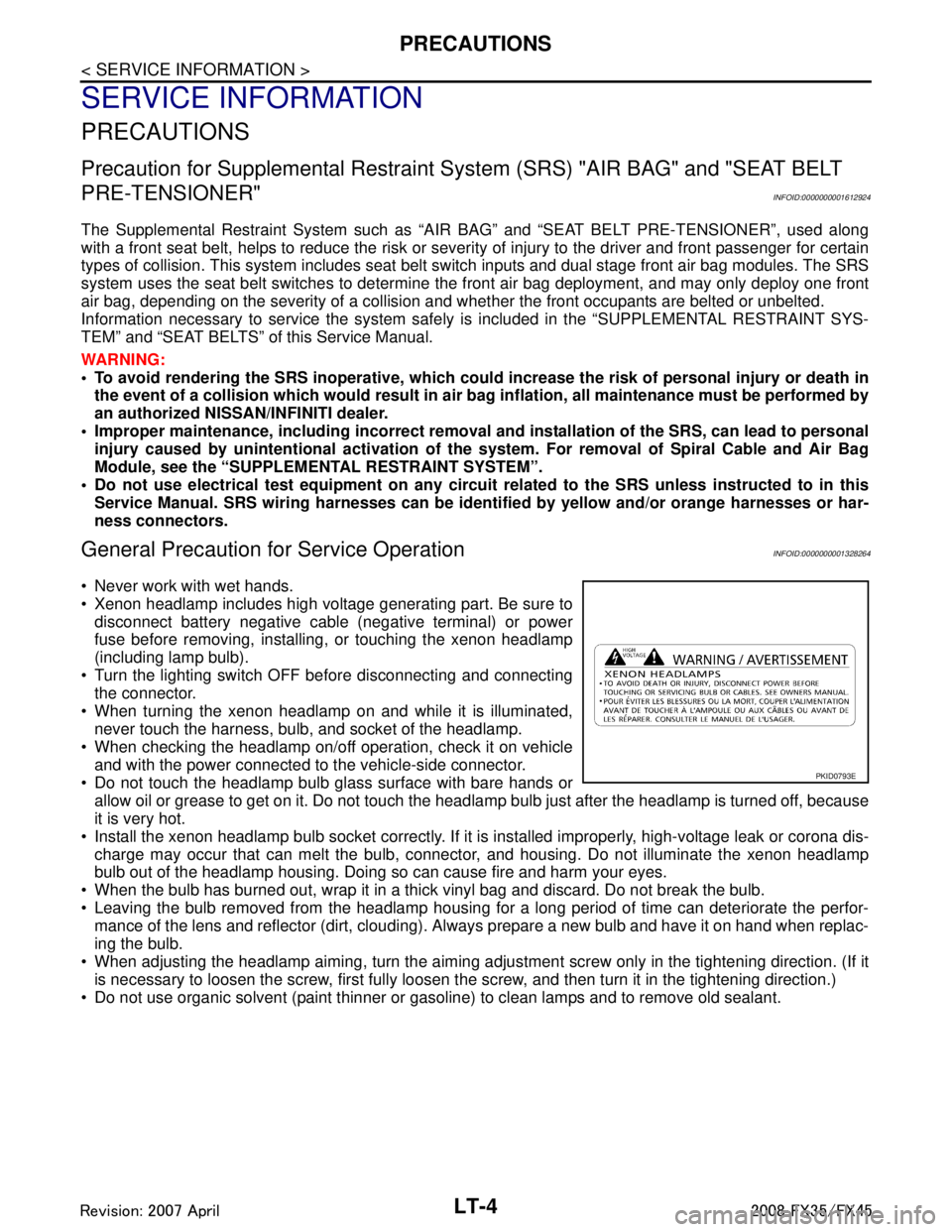
Xenon headlamp includes high voltage generating part. Be sure to disconnect battery negative cable (negative terminal) or power
fuse before removing, installing, or touching the xenon headlamp
(including lamp bulb).
Turn the lighting switch OFF before disconnecting and connecting the connector.
When turning the xenon headlamp on and while it is illuminated, never touch the harness, bulb, and socket of the headlamp.
When checking the headlamp on/off operation, check it on vehicle
and with the power connected to the vehicle-side connector.
Do not touch the headlamp bulb glass surface with bare hands or allow oil or grease to get on it. Do not touch the headl amp bulb just after the headlamp is turned off, because
it is very hot.
Install the xenon headlamp bulb socket co rrectly. If it is installed improperly, high-voltage leak or corona dis-
charge may occur that can melt the bulb, connecto r, and housing. Do not illuminate the xenon headlamp
bulb out of the headlamp housing. Doing so can cause fire and harm your eyes.
When the bulb has burned out, wrap it in a thick vinyl bag and discard. Do not break the bulb.
Leaving the bulb removed from the headlamp housing for a long period of time can deteriorate the perfor- mance of the lens and reflector (dirt, clouding). Al ways prepare a new bulb and have it on hand when replac-
ing the bulb.
When adjusting the headlamp aiming, turn the aiming adjus tment screw only in the tightening direction. (If it
is necessary to loosen the screw, first fully loosen the screw, and then turn it in the tightening direction.)
Do not use organic solvent (paint thinner or gasoline) to clean lamps and to remove old sealant.
PKID0793E
3AA93ABC3ACD3AC03ACA3AC03AC63AC53A913A773A893A873A873A8E3A773A983AC73AC93AC03AC3
3A893A873A873A8F3A773A9D3AAF3A8A3A8C3A863A9D3AAF3A8B3A8C
Page 3271 of 3924
ILLUMINATIONLT-169
< SERVICE INFORMATION >
C
DE
F
G H
I
J
L
M A
B
LT
N
O P
ILLUMINATION
System DescriptionINFOID:0000000001328422
Control of illumination lamps operation is dependent upon position of lighting switch (combination switch).
When lighting switch is placed in the 1ST or 2ND positi on (or if auto light system is activated), BCM (body con-
trol module) receives input signal requesting illuminati on lamps to illuminate. This input signal is communi-
cated to IPDM E/R (intelligent power distribution module engine room) through the CAN communication. The
CPU (central processing unit) located in the IPDM E/R co ntrols tail lamp relay coil. This relay, when energized,
directs power to illumination lamps, which then illuminate.
Power is supplied at all times
through 10A fuse (No. 71, located in IPDM E/R)
to tail lamp relay, located in IPDM E/R, and
to CPU located in IPDM E/R.
Power is also supplied at all times
through 50A fusible link (letter M, located in fuse, fusible link and relay box)
to BCM terminal 55,
through 15A fuse [No. 22 located in fuse block (J/B)]
to BCM terminal 42,
through 15A fuse (No. 78, located in IPDM E/R)
to CPU located in IPDM E/R,
through 10A fuse [No. 19 located in fuse block (J/B)]
to unified meter and A/C amp. terminal 21 and
to combination meter terminal 8.
With ignition switch in ON or START position, power is supplied
to ignition relay, located in IPDM E/R, from battery direct,
through 15A fuse [No. 1 located in fuse block (J/B)]
to BCM terminal 38,
through 10A fuse [No. 12, located in fuse block (J/B)]
to unified meter and A/C amp. terminal 22 and
to combination meter terminal 7.
With ignition switch in ACC or ON position, power is supplied
through 10A fuse [No. 6, located in fuse block (J/B)]
to combination meter terminal 4 and
to BCM terminal 11.
Ground is supplied
to BCM terminals 49 and 52
to unified meter and A/C amp. terminals 29 and 30, and
to combination meter terminals 5, 6, and 15
through grounds M35, M45, and M85,
to IPDM E/R terminals 38 and 60
through grounds E21, E50, and E51.
ILLUMINATION OPERATION BY LIGHTING SWITCH
With lighting switch in the 1ST or 2ND position (or if auto light system is activated), BCM receives input signal
requesting illumination lamps to illuminate. This input signal is communicated to IPDM E/R through the CAN
communication. The CPU located in the IPDM E/R controls tail lamp relay coil, which, when energized, directs
power
through IPDM E/R terminal 22
to glove box lamp terminal 1
to A/T device (illumination) terminal 11
to snow mode switch (illumination) terminal 5
to VDC off switch (illumination) terminal 3
to clock (illumination) terminal 3
to hazard switch (illumination) terminal 3
to heated seat switch (driver side) (illumination) terminal 5
to heated seat switch (passenger side) (illumination) terminal 5
to door mirror remote control switch (illumination) terminal 16
to LDW switch (illumination) terminal 5
to combination switch (spiral cable) terminal 26
to microphone terminal 2 (with telephone system)
3AA93ABC3ACD3AC03ACA3AC03AC63AC53A913A773A893A873A873A8E3A773A983AC73AC93AC03AC3
3A893A873A873A8F3A773A9D3AAF3A8A3A8C3A863A9D3AAF3A8B3A8C
Page 3272 of 3924
LT-170
< SERVICE INFORMATION >
ILLUMINATION
to A/C and AV switch (illumination) terminal 3
to DVD player (illumination) terminal 12
to coin box illumination terminal 2 and
to rear power window switch LH and RH (illumination) terminals 6,
through combination switch (spiral cable) terminal 18
to audio steering switch (illumination)
to icc steering switch (illumination) (with icc) and
to ascd steering switch (illumination) (without icc)
Illumination control
through combination meter terminal 19
to A/T device (illumination) terminal 12
to snow mode switch (illumination) terminal 6
to VDC off switch (illumination) terminal 4
to clock (illumination) terminal 4
to hazard switch (illumination) terminal 4
to heated seat switch (driver side) (illumination) terminal 6
to heated seat switch (passenger side) (illumination) terminal 6
to door mirror remote control switch terminal 15
to LDW switch (illumination) terminal 4,
to combination switch (spiral cable) terminal 27
to A/C and AV switch (illumination) terminal 4 and
to DVD player (illumination) terminal 10,
through combination switch (spiral cable) terminal 21
to audio steering switch (illumination)
to icc steering switch (illumination) (with icc) and
to ascd steering switch (illumination) (without icc)
Ground is supplied at all times
to glove box lamp terminal 2 and
to coin box illumination terminal 3
through grounds M35, M45 and M85,
to rear power window switch LH and RH (illumination) terminals 7
through grounds B15 and B45.
With power and ground supplied, illumination lamps illuminate.
EXTERIOR LAMP BATTERY SAVER CONTROL
When the lighting switch is in the 1ST or 2ND position (or if auto light system is activated), and ignition switch
is turned from ON or ACC to OFF, batte ry saver control function is activated.
Under this condition, illumination lamps remain illuminated for 5 minutes, then illumination lamps are turned
off.
When the lighting switch is turned from OFF to 1ST or 2 ND position (or if auto light system is activated) after
illumination lamps are turned off by battery save r control, and illumination lamps illuminate again.
Exterior lamp battery saver control mode can be changed by the function setting of CONSULT-III.
CAN Communication System DescriptionINFOID:0000000001328423
CAN (Controller Area Network) is a serial communication line for real time application. It is an on-vehicle mul-
tiplex communication line with high data communication s peed and excellent error detection ability. Many elec-
tronic control units are equipped onto a vehicle, and each control unit shares information and links with other
control units during operation (not independent). In CA N communication, control units are connected with 2
communication lines (CAN H line, CAN L line) allowing a high rate of information transmission with less wiring.
Each control unit transmits/receives data but selectively reads required data only.
CAN Communication UnitINFOID:0000000001328424
Refer to LAN-43, "CAN System Specification Chart".
3AA93ABC3ACD3AC03ACA3AC03AC63AC53A913A773A893A873A873A8E3A773A983AC73AC93AC03AC3
3A893A873A873A8F3A773A9D3AAF3A8A3A8C3A863A9D3AAF3A8B3A8C
Page 3318 of 3924
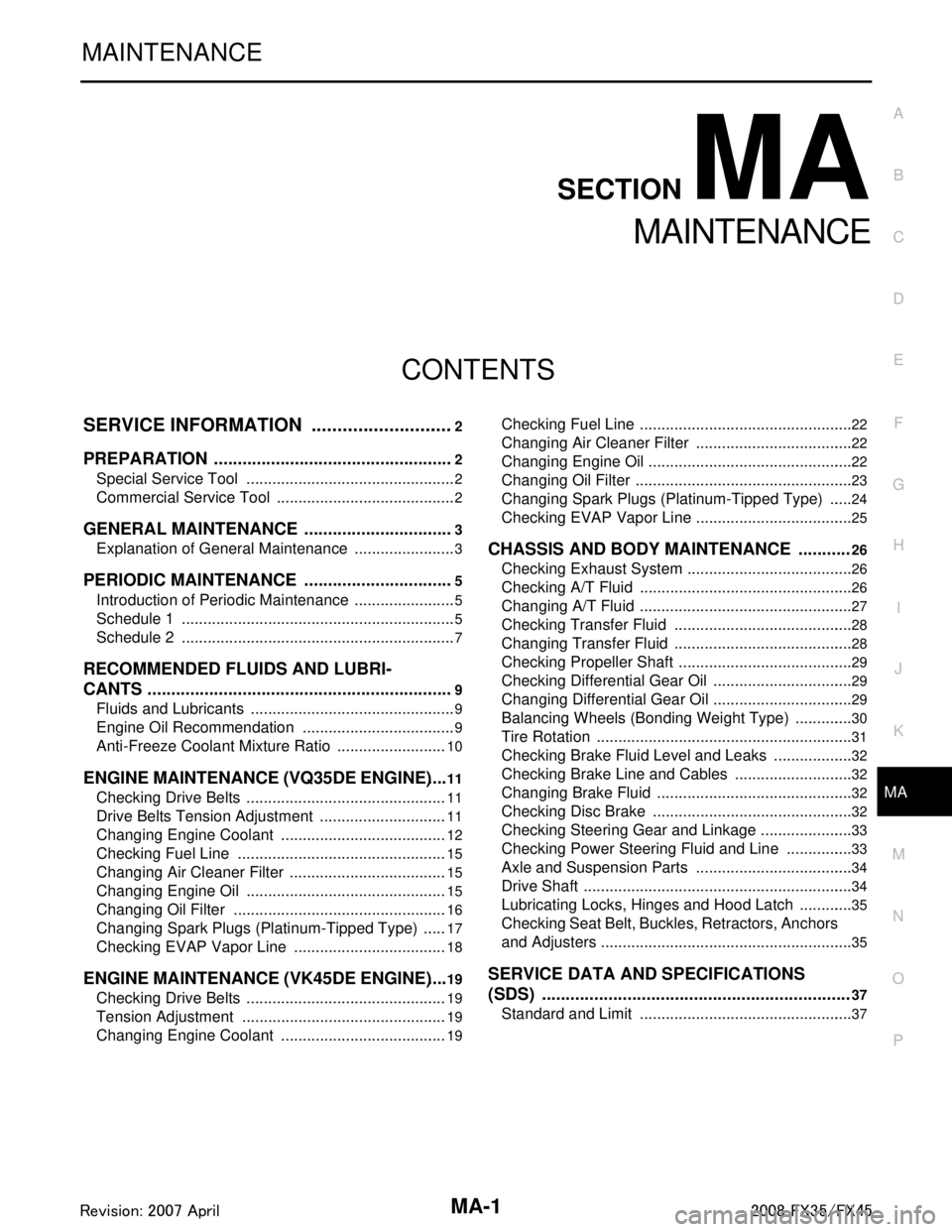
MA-1
MAINTENANCE
C
DE
F
G H
I
J
K
M
SECTION MA
A
B
MA
N
O P
CONTENTS
MAINTENANCE
SERVICE INFORMATION .. ..........................2
PREPARATION .............................................. .....2
Special Service Tool ........................................... ......2
Commercial Service Tool ..........................................2
GENERAL MAINTENANCE ................................3
Explanation of General Maintenance .................. ......3
PERIODIC MAINTENANCE ................................5
Introduction of Periodic Maintenance .................. ......5
Schedule 1 ................................................................5
Schedule 2 ................................................................7
RECOMMENDED FLUIDS AND LUBRI-
CANTS .................................................................
9
Fluids and Lubricants .......................................... ......9
Engine Oil Recommendation ....................................9
Anti-Freeze Coolant Mixture Ratio ..........................10
ENGINE MAINTENANCE (VQ35DE ENGINE) ....11
Checking Drive Belts ........................................... ....11
Drive Belts Tension Adjustment ..............................11
Changing Engine Coolant .......................................12
Checking Fuel Line .................................................15
Changing Air Cleaner Filter .....................................15
Changing Engine Oil ...............................................15
Changing Oil Filter ..................................................16
Changing Spark Plugs (Platinum-Tipped Type) ......17
Checking EVAP Vapor Line ....................................18
ENGINE MAINTENANCE (VK45DE ENGINE) ....19
Checking Drive Belts ........................................... ....19
Tension Adjustment ................................................19
Changing Engine Coolant .......................................19
Checking Fuel Line .............................................. ....22
Changing Air Cleaner Filter .....................................22
Changing Engine Oil ................................................22
Changing Oil Filter ...................................................23
Changing Spark Plugs (Platinum-Tipped Type) ......24
Checking EVAP Vapor Line .....................................25
CHASSIS AND BODY MAINTENANCE ...........26
Checking Exhaust System ................................... ....26
Checking A/T Fluid ..................................................26
Changing A/T Fluid ..................................................27
Checking Transfer Fluid ..........................................28
Changing Transfer Fluid ..........................................28
Checking Propeller Shaft .........................................29
Checking Differential Gear Oil .................................29
Changing Differential Gear Oil .................................29
Balancing Wheels (Bonding Weight Type) ..............30
Tire Rotation ............................................................31
Checking Brake Fluid Level and Leaks ...................32
Checking Brake Line and Cables ............................32
Changing Brake Fluid ..............................................32
Checking Disc Brake ...............................................32
Checking Steering Gear and Linkage ......................33
Checking Power Steering Fluid and Line ................33
Axle and Suspension Parts .....................................34
Drive Shaft ...............................................................34
Lubricating Locks, Hinges and Hood Latch .............35
Checking Seat Belt, Buckles, Retractors, Anchors
and Adjusters ...........................................................
35
SERVICE DATA AND SPECIFICATIONS
(SDS) .................................................................
37
Standard and Limit ..................................................37
3AA93ABC3ACD3AC03ACA3AC03AC63AC53A913A773A893A873A873A8E3A773A983AC73AC93AC03AC3
3A893A873A873A8F3A773A9D3AAF3A8A3A8C3A863A9D3AAF3A8B3A8C