2008 INFINITI FX35 power seat
[x] Cancel search: power seatPage 1188 of 3924

DI-62
< SERVICE INFORMATION >
WARNING CHIME
OK or NG
OK >> GO TO 2.
NG >> Be sure to eliminate cause of malfunction before installing new fuse or fusible link. Refer to PG-3
.
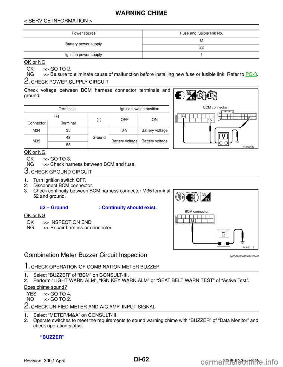
2.CHECK POWER SUPPLY CIRCUIT
Check voltage between BCM harness connector terminals and
ground.
OK or NG
OK >> GO TO 3.
NG >> Check harness between BCM and fuse.
3.CHECK GROUND CIRCUIT
1. Turn ignition switch OFF.
2. Disconnect BCM connector.
3. Check continuity between BCM harness connector M35 terminal 52 and ground.
OK or NG
OK >> INSPECTION END
NG >> Repair harness or connector.
Combination Meter Buzzer Circuit InspectionINFOID:0000000001328485
1.CHECK OPERATION OF COMBINATION METER BUZZER
1. Select “BUZZER” of “BCM” on CONSULT-III.
2. Perform “LIGHT WARN ALM”, “IGN KEY WARN AL M” or “SEAT BELT WARN TEST” of “Active Test”.
Does chime sound?
YES >> GO TO 4.
NO >> GO TO 2.
2.CHECK UNIFIED METER AND A/C AMP. INPUT SIGNAL
1. Select “METER/M&A” on CONSULT-III.
2. Operate switches to meet the requirements to s ound warning chime with “BUZZER” of “Data Monitor” and
check operation status.
Power source Fuse and fusible link No.
Battery power supply M
22
Ignition power supply 1
Terminals Ignition switch position
(+) (–) OFF ON
Connector Terminal
M34 38 Ground0 V Battery voltage
M35 42
Battery voltage Battery voltage
55
PKIB3988E
52 – Ground : Continui ty should exist.
PKIB5011E
“BUZZER”
3AA93ABC3ACD3AC03ACA3AC03AC63AC53A913A773A893A873A873A8E3A773A983AC73AC93AC03AC3
3A893A873A873A8F3A773A9D3AAF3A8A3A8C3A863A9D3AAF3A8B3A8C
Page 2139 of 3924
![INFINITI FX35 2008 Service Manual
DTC P0300 - P0308 MULTIPLE CYLINDER MISFIRE, NO. 1 - 8 CYLINDER MIS-
FIRE
EC-899
< SERVICE INFORMATION > [VK45DE]
C
D
E
F
G H
I
J
K L
M A
EC
NP
O
NG >> GO TO 7.
7.CHECK FUNCTION OF
IGNITION COIL-II
INFINITI FX35 2008 Service Manual
DTC P0300 - P0308 MULTIPLE CYLINDER MISFIRE, NO. 1 - 8 CYLINDER MIS-
FIRE
EC-899
< SERVICE INFORMATION > [VK45DE]
C
D
E
F
G H
I
J
K L
M A
EC
NP
O
NG >> GO TO 7.
7.CHECK FUNCTION OF
IGNITION COIL-II](/manual-img/42/57017/w960_57017-2138.png)
DTC P0300 - P0308 MULTIPLE CYLINDER MISFIRE, NO. 1 - 8 CYLINDER MIS-
FIRE
EC-899
< SERVICE INFORMATION > [VK45DE]
C
D
E
F
G H
I
J
K L
M A
EC
NP
O
NG >> GO TO 7.
7.CHECK FUNCTION OF
IGNITION COIL-II
1. Turn ignition switch OFF.
2. Disconnect spark plug and connect a known-good spark plug.
3. Crank engine for about three seconds, and recheck whether spark is generated between the spark plug and the grounded metal portion.
OK or NG
OK >> GO TO 8.
NG >> Check ignition coil, power transistor and their circuits. Refer to EC-1166
.
8.CHECK SPARK PLUG
Check the initial spark plug for fouling, etc.
OK or NG
OK >> Replace malfunctioning spark plug(s) with standard type one(s). For spark plug type, refer to EM-188
.
NG >> 1. Repair or clean spark plug.
2. GO TO 9.
9.CHECK FUNCTION OF IGNITION COIL-III
1. Reconnect the initial spark plugs.
2. Crank engine for about three seconds, and recheck whether spark is generated between the spark plug and the grounded portion.
OK or NG
OK >> INSPECTION END
NG >> Replace malfunctioning spark plug(s) with standard type one(s). For spark plug type, refer to EM-
188.
10.CHECK COMPRESSION PRESSURE
Check compression pressure. Refer to EM-226, "
On-Vehicle Service".
OK or NG
OK >> GO TO 11.
NG >> Check pistons, piston rings, valves, valve seats and cylinder head gaskets.
11 .CHECK FUEL PRESSURE
1. Install all removed parts.
2. Release fuel pressure to zero. Refer to EC-665, "
Fuel Pressure Check".
3. Install fuel pressure gauge and check fuel pressure. Refer to EC-665, "
Fuel Pressure Check".
OK or NG
OK >> GO TO 13.
NG >> GO TO 12.
12.DETECT MALFUNCTIONING PART
Check the following.
Fuel pump and circuit (Refer to EC-1155
.)
Fuel pressure regulator (Refer to EC-665, "
Fuel Pressure Check".)
Spark should be generated.
SEF156I
Spark should be generated.
At idling: Approximate
ly 350 kPa (3.57 kg/cm
2, 51 psi)
3AA93ABC3ACD3AC03ACA3AC03AC63AC53A913A773A893A873A873A8E3A773A983AC73AC93AC03AC3
3A893A873A873A8F3A773A9D3AAF3A8A3A8C3A863A9D3AAF3A8B3A8C
Page 2474 of 3924

DOOR FINISHEREI-37
< SERVICE INFORMATION >
C
DE
F
G H
J
K L
M A
B
EI
N
O P
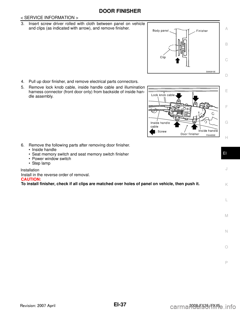
3. Insert screw driver rolled with cloth between panel on vehicle and clips (as indicated with arrow), and remove finisher.
4. Pull up door finisher, and remove electrical parts connectors.
5. Remove lock knob cable, inside handle cable and illumination harness connector (front door only) from backside of inside han-
dle assembly.
6. Remove the following parts after removing door finisher. Inside handle
Seat memory switch and seat memory switch finisher
Power window switch
Step lamp
Installation
Install in the reverse order of removal.
CAUTION:
To install finisher, check if all clips are matched over holes of panel on vehicle, then push it.
SIIA0810E
PIIA4959E
3AA93ABC3ACD3AC03ACA3AC03AC63AC53A913A773A893A873A873A8E3A773A983AC73AC93AC03AC3
3A893A873A873A8F3A773A9D3AAF3A8A3A8C3A863A9D3AAF3A8B3A8C
Page 2483 of 3924

EI-46
< SERVICE INFORMATION >
LUGGAGE FLOOR TRIM
Removal and Installation
INFOID:0000000001529413
REMOVAL
1. Remove tonneau cover.
2. Remove luggage side hook and remove net hook (RH/LH).
3. Remove luggage floor board assembly. Remove bolt with power tool.
4. Remove luggage floor side board assembly (RH/LH).
5. Remove back door weather strip.
6. Remove rear plate assembly.
7. Remove roof rear garnish assembly.
8. Remove luggage floor cover assembly (RH/LH).
9. Remove rear door kicking plate (RH/LH).
10. Remove rear body side welt.
11. Remove rear seat cushion and seatback. Refer to SE-95, "
Removal and Installation".
12. Remove rear wheel house finisher assembly (RH/LH).
13. Remove luggage side finisher assembly bolt and remove luggage side finisher assembly (RH/LH).
14. Remove bolt, and then remove parcel shelf holder.
15. Remove rear parcel shelf cap.
16. Remove bolt, and then remove rear parcel hook.
17. Remove rear seat belt anchor (RH/LH). Refer to SB-5, "
Removal and Installation of Rear Seat Belt".
18. Remove rear pillar upper garnish assembly cap and bolt, then remove rear pillar upper garnish assembly (RH/LH).
19. Remove spare tire clamp.
20. Remove sub-woofer box connector and remove sub-woofer box.
21. Remove spare tire.
22. Remove towing hook, wheel nut wrench, spanner, tire stopper, jack rod and jack complete.
23. Remove luggage side box bolt and luggage side box assembly (RH/LH).
INSTALLATION
Install in the reverse order of removal.
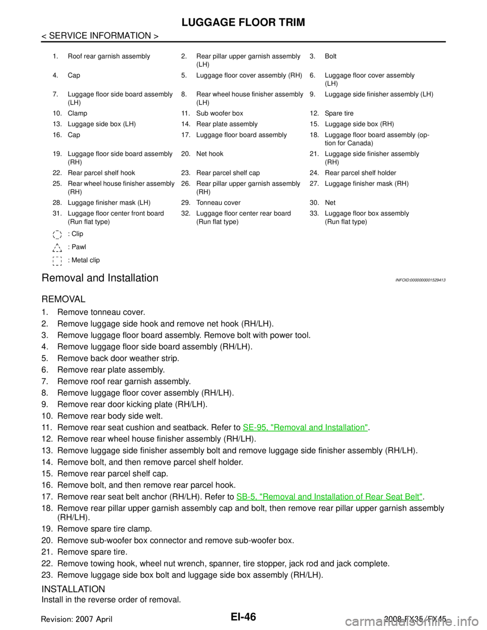
1. Roof rear garnish assembly 2. Rear pillar upper garnish assembly (LH)3. Bolt
4. Cap 5. Luggage floor cover assembly (RH) 6. Luggage floor cover assembly (LH)
7. Luggage floor side board assembly (LH) 8. Rear wheel house finisher assembly
(LH) 9. Luggage side finisher assembly (LH)
10. Clamp 11. Sub woofer box 12. Spare tire
13. Luggage side box (LH) 14. Rear plate assembly 15. Luggage side box (RH)
16. Cap 17. Luggage floor board assembly 18. Luggage floor board assembly (op- tion for Canada)
19. Luggage floor side board assembly (RH) 20. Net hook 21. Luggage side finisher assembly
(RH)
22. Rear parcel shelf hook 23. Rear parcel shelf cap 24. Rear parcel shelf holder
25. Rear wheel house finisher assembly (RH) 26. Rear pillar upper garnish assembly
(RH) 27. Luggage finisher mask (RH)
28. Luggage finisher mask (LH) 29. Tonneau cover 30. Net
31. Luggage floor center front board (Run flat type) 32. Luggage floor center rear board
(Run flat type) 33. Luggage floor box assembly
(Run flat type)
: Clip
: Pawl
: Metal clip
3AA93ABC3ACD3AC03ACA3AC03AC63AC53A913A773A893A873A873A8E3A773A983AC73AC93AC03AC3
3A893A873A873A8F3A773A9D3AAF3A8A3A8C3A863A9D3AAF3A8B3A8C
Page 2600 of 3924
![INFINITI FX35 2008 Service Manual
EM-116
< SERVICE INFORMATION >[VQ35DE]
ENGINE ASSEMBLY
When installing engine mounting bracket (RH and LH) on cylinder
block, tighten two upper bolts (show n as “A” in the figure) first.
Then t INFINITI FX35 2008 Service Manual
EM-116
< SERVICE INFORMATION >[VQ35DE]
ENGINE ASSEMBLY
When installing engine mounting bracket (RH and LH) on cylinder
block, tighten two upper bolts (show n as “A” in the figure) first.
Then t](/manual-img/42/57017/w960_57017-2599.png)
EM-116
< SERVICE INFORMATION >[VQ35DE]
ENGINE ASSEMBLY
When installing engine mounting bracket (RH and LH) on cylinder
block, tighten two upper bolts (show n as “A” in the figure) first.
Then tighten two lower bolts (shown as “B” in the figure).
Make sure all engine mounting insulators are seated properly, then tighten mounting nuts.
Tighten rear engine mounting member bolts in numerical order as shown in the figure.
INSPECTION AFTER INSTALLATION
Inspection for Leaks
The following are procedures for checking fluids leak, lubricates leak and exhaust gases leak. Before starting engine, check oil/fluid levels incl uding engine coolant and engine oil. If less than required
quantity, fill to the specified level. Refer to MA-9, "
Fluids and Lubricants".
Use procedure below to check for fuel leakage.
- Turn ignition switch “ON” (with engine stopped). With fuel pressure applied to fuel piping, check for fuel leak-
age at connection points.
- Start engine. With engine speed increased, che ck again for fuel leakage at connection points.
Run engine to check for unusual noise and vibration.
Warm up engine thoroughly to make sure there is no leak age of fuel, exhaust gases, or any oil/fluids includ-
ing engine oil and engine coolant.
Bleed air from lines and hoses of applic able lines, such as in cooling system.
After cooling down engine, again check oil/fluid levels including engine oil and engine coolant. Refill to the specified level, if necessary.
Summary of the inspection items:
*: Transmission/transaxle/CVT fluid. power steering fluid, brake fluid, etc.
PBIC2062E
PBIC3040E
Items Before starting engine Engine running After engine stopped
Engine coolant Level Leakage Level
Engine oil Level Leakage Level
Other oils and fluid* Level Leakage Level
Fuel Leakage Leakage Leakage
Exhaust gases — Leakage —
3AA93ABC3ACD3AC03ACA3AC03AC63AC53A913A773A893A873A873A8E3A773A983AC73AC93AC03AC3
3A893A873A873A8F3A773A9D3AAF3A8A3A8C3A863A9D3AAF3A8B3A8C
Page 2605 of 3924
![INFINITI FX35 2008 Service Manual
ENGINE ASSEMBLYEM-121
< SERVICE INFORMATION > [VQ35DE]
C
D
E
F
G H
I
J
K L
M A
EM
NP
O
When installing engine mounting bracket (RH and LH) on cylinder
block, tighten two upper bolts (shown as “A� INFINITI FX35 2008 Service Manual
ENGINE ASSEMBLYEM-121
< SERVICE INFORMATION > [VQ35DE]
C
D
E
F
G H
I
J
K L
M A
EM
NP
O
When installing engine mounting bracket (RH and LH) on cylinder
block, tighten two upper bolts (shown as “A�](/manual-img/42/57017/w960_57017-2604.png)
ENGINE ASSEMBLYEM-121
< SERVICE INFORMATION > [VQ35DE]
C
D
E
F
G H
I
J
K L
M A
EM
NP
O
When installing engine mounting bracket (RH and LH) on cylinder
block, tighten two upper bolts (shown as “A” in the figure) first.
Then tighten two lower bolts (shown as “B” in the figure).
Install engine mounting bracket (RH) (lower) as follows:
- Temporarily tighten mounting bolts (shown as “C”, “D” and “E” in the figure).
- Tighten mounting bolts to the specified torque with following mounting surfaces touched.
Engine mounting bracket (RH) to engine mounting bracket (RH)
(lower) (shown as “C” and “D” in figure).
Front final drive to engine mounting bracket (RH) (lower) (shown as “E” in figure).
Make sure all engine mounting insulators are seated properly, then
tighten mounting nuts.
INSPECTION AFTER INSTALLATION
Inspection for Leaks
The following are procedures for checking fluids leak, lubricates leak and exhaust gases leak.
Before starting engine, check oil/fluid levels incl uding engine coolant and engine oil. If less than required
quantity, fill to the specified level. Refer to MA-9, "
Fluids and Lubricants".
Use procedure below to check for fuel leakage.
- Turn ignition switch “ON” (with engine stopped). With fuel pressure applied to fuel piping, check for fuel leak-
age at connection points.
- Start engine. With engine speed increased, check again for fuel leakage at connection points.
Run engine to check for unusual noise and vibration.
Warm up engine thoroughly to make sure there is no leak age of fuel, exhaust gases, or any oil/fluids includ-
ing engine oil and engine coolant.
Bleed air from lines and hoses of applicable lines, such as in cooling system.
After cooling down engine, again check oil/fluid levels including engine oil and engine coolant. Refill to the specified level, if necessary.
Summary of the inspection items:
*: Transmission/transaxle/CVT fluid. power steering fluid, brake fluid, etc.
PBIC3042E
Items Before starting engine Engine running After engine stopped
Engine coolant Level Leakage Level
Engine oil Level Leakage Level
Other oils and fluid* Level Leakage Level
Fuel Leakage Leakage Leakage
Exhaust gases — Leakage —
3AA93ABC3ACD3AC03ACA3AC03AC63AC53A913A773A893A873A873A8E3A773A983AC73AC93AC03AC3
3A893A873A873A8F3A773A9D3AAF3A8A3A8C3A863A9D3AAF3A8B3A8C
Page 2649 of 3924
![INFINITI FX35 2008 Service Manual
PREPARATIONEM-165
< SERVICE INFORMATION > [VK45DE]
C
D
E
F
G H
I
J
K L
M A
EM
NP
O
(Kent-Moore No.)
Tool name
Description
(—)
Tube presser Pressing the tube of liquid gasket
(—)
Power tool Loosen INFINITI FX35 2008 Service Manual
PREPARATIONEM-165
< SERVICE INFORMATION > [VK45DE]
C
D
E
F
G H
I
J
K L
M A
EM
NP
O
(Kent-Moore No.)
Tool name
Description
(—)
Tube presser Pressing the tube of liquid gasket
(—)
Power tool Loosen](/manual-img/42/57017/w960_57017-2648.png)
PREPARATIONEM-165
< SERVICE INFORMATION > [VK45DE]
C
D
E
F
G H
I
J
K L
M A
EM
NP
O
(Kent-Moore No.)
Tool name
Description
(—)
Tube presser Pressing the tube of liquid gasket
(—)
Power tool Loosening nuts and bolts
(—)
Spark plug wrench Removing and installing spark plug
(—)
Manual lift table caddy Removing and installing engine
(J–24239-01)
Cylinder head bolt wrench Loosening and tightening cylinder head bolt,
and use with angle wrench [SST:
KV10112100 (BT–8653-A)]
a: 13 (0.51) dia.
b: 12 (0.47)
c: 10 (0.39)
Unit: mm (in)
(—)
Valve seat cutter set Finishing valve seat dimensions
(—)
Piston ring expander Removing and installing piston ring
S-NT052
PBIC0190E
S-NT047
ZZA1210D
NT583
S-NT048
S-NT030
3AA93ABC3ACD3AC03ACA3AC03AC63AC53A913A773A893A873A873A8E3A773A983AC73AC93AC03AC3
3A893A873A873A8F3A773A9D3AAF3A8A3A8C3A863A9D3AAF3A8B3A8C
Page 2864 of 3924

GI-2
< SERVICE INFORMATION >
PRECAUTIONS
SERVICE INFORMATION
PRECAUTIONS
DescriptionINFOID:0000000001325649
Observe the following precautions to ensure safe and proper servicing. These precautions are not
described in each individual section.
Precaution for Supplemental Restraint S ystem (SRS) "AIR BAG" and "SEAT BELT
PRE-TENSIONER"
INFOID:0000000001612904
The Supplemental Restraint System such as “A IR BAG” and “SEAT BELT PRE-TENSIONER”, used along
with a front seat belt, helps to reduce the risk or severi ty of injury to the driver and front passenger for certain
types of collision. This system includes seat belt switch inputs and dual stage front air bag modules. The SRS
system uses the seat belt switches to determine the front air bag deployment, and may only deploy one front
air bag, depending on the severity of a collision and w hether the front occupants are belted or unbelted.
Information necessary to service the system safely is included in the “SUPPLEMENTAL RESTRAINT SYS-
TEM” and “SEAT BELTS” of this Service Manual.
WARNING:
• To avoid rendering the SRS inopera tive, which could increase the risk of personal injury or death in
the event of a collision which would result in air bag inflation, all maintenance must be performed by
an authorized NISS AN/INFINITI dealer.
Improper maintenance, including in correct removal and installation of the SRS, can lead to personal
injury caused by unintent ional activation of the system. For re moval of Spiral Cable and Air Bag
Module, see the “SUPPLEMEN TAL RESTRAINT SYSTEM”.
Do not use electrical test equipmen t on any circuit related to the SRS unless instructed to in this
Service Manual. SRS wiring harnesses can be identi fied by yellow and/or orange harnesses or har-
ness connectors.
Precaution Necessary for Steering W heel Rotation After Battery Disconnect
INFOID:0000000001612934
NOTE:
This Procedure is applied only to models with In telligent Key system and NVIS/IVIS (NISSAN/INFINITI
VEHICLE IMMOBILIZER SYSTEM - NATS).
Remove and install all control units after disconnecting both battery cables with the ignition knob in the ″LOCK ″ position.
Always use CONSULT-III to perform self-diagnosis as a part of each function inspection after finishing work.
If DTC is detected, perform trouble diagnosis according to self-diagnostic results.
For models equipped with the Intelligent Key system and NVIS /IVIS, an electrically controlled steering lock
mechanism is adopted on the key cylinder.
For this reason, if the battery is disconnected or if the battery is discharged, the steering wheel will lock and
steering wheel rotation will become impossible.
If steering wheel rotation is required when battery pow er is interrupted, follow the procedure below before
starting the repair operation.
OPERATION PROCEDURE
1. Connect both battery cables. NOTE:
Supply power using jumper cables if battery is discharged.
2. Use the Intelligent Key or mechanical key to turn the ignition switch to the ″ACC ″ position. At this time, the
steering lock will be released.
3. Disconnect both battery cables. The steering lock will remain released and the steering wheel can be
rotated.
4. Perform the necessary repair operation.
5. When the repair work is completed, return the ignition switch to the ″LOCK ″ position before connecting
the battery cables. (At this time, the steering lock mechanism will engage.)
6. Perform a self-diagnosis check of all control units using CONSULT-III.
3AA93ABC3ACD3AC03ACA3AC03AC63AC53A913A773A893A873A873A8E3A773A983AC73AC93AC03AC3
3A893A873A873A8F3A773A9D3AAF3A8A3A8C3A863A9D3AAF3A8B3A8C