2008 INFINITI FX35 seal
[x] Cancel search: sealPage 3590 of 3924
SHOCK ABSORBERRSU-9
< SERVICE INFORMATION >
C
DF
G H
I
J
K L
M A
B
RSU
N
O P
SHOCK ABSORBER
Removal and InstallationINFOID:0000000001327555
REMOVAL
1. Remove tires from vehicle with power tool.
2. Set jack under rear lower link.
3. Remove fixing bolt in lower side of shock absorber assembly with power tool.
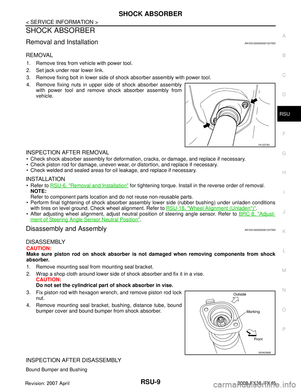
4. Remove fixing nuts in upper side of shock absorber assembly with power tool and remove shock absorber assembly from
vehicle.
INSPECTION AFTER REMOVAL
Check shock absorber assembly for deformation, cracks, or damage, and replace if necessary.
Check piston rod for damage, uneven wear, or distortion, and replace if necessary.
Check welded and sealed areas for oil leakage, and replace if necessary.
INSTALLATION
Refer to RSU-6, "Removal and Installation" for tightening torque. Install in the reverse order of removal.
NOTE:
Refer to component parts location and do not reuse non-reusable parts.
Perform final tightening of shock absorber assembly lower side (rubber b\
ushing) under unladen conditions
with tires on level ground. Check wheel alignment. Refer to RSU-18, "
Wheel Alignment (Unladen*)".
After adjusting wheel alignment, adjust neutral position of steering angle sensor. Refer to BRC-8, "
Adjust-
ment of Steering Angle Sensor Neutral Position".
Disassembly and AssemblyINFOID:0000000001327556
DISASSEMBLY
CAUTION:
Make sure piston rod on shock absorber is not damaged when removing components from shock
absorber.
1. Remove mounting seal fr om mounting seal bracket.
2. Wrap a shop cloth around lower side of shock absorber and fix it in a vise. CAUTION:
Do not set the cylindrical part of shock absorber in vise.
3. Fix piston rod with hexagon wrench, and remove piston rod lock nut.
4. Remove mounting seal bracke t, bushing, distance tube, bound
bumper cover and bound bumper from shock absorber.
INSPECTION AFTER DISASSEMBLY
Bound Bumper and Bushing
FA-0274D
SEIA0366E
3AA93ABC3ACD3AC03ACA3AC03AC63AC53A913A773A893A873A873A8E3A773A983AC73AC93AC03AC3
3A893A873A873A8F3A773A9D3AAF3A8A3A8C3A863A9D3AAF3A8B3A8C
Page 3637 of 3924
SC-28
< SERVICE INFORMATION >
CHARGING SYSTEM
Make sure that alternator pulley nut is tight.
INSTALLATION
Installation is the reverse order of removal.
Install alternator, and check tension of belt. Refer to EM-14, "Checking Drive Belts".
CAUTION:
Be sure to tighten “B” terminal nut carefully.
Disassembly and AssemblyINFOID:0000000001328259
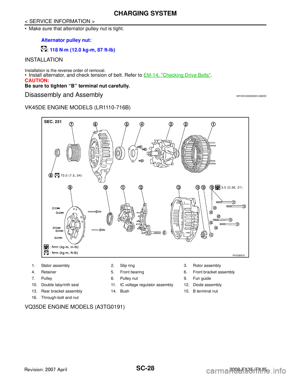
VK45DE ENGINE MODELS (LR1110-716B)
VQ35DE ENGINE MODELS (A3TG0191)
Alternator pulley nut:
: 118 N·m (12.0 kg-m, 87 ft-lb)
1. Stator assembly 2. Slip ring 3. Rotor assembly
4. Retainer 5. Front bearing 6. Front bracket assembly
7. Pulley 8. Pulley nut 9. Fun guide
10. Double labyrinth seal 11. IC voltage regulator assembly 12. Diode assembly
13. Rear bracket assembly 14. Bush 15. B terminal nut
16. Through-bolt and nut
PKID0691E
3AA93ABC3ACD3AC03ACA3AC03AC63AC53A913A773A893A873A873A8E3A773A983AC73AC93AC03AC3
3A893A873A873A8F3A773A9D3AAF3A8A3A8C3A863A9D3AAF3A8B3A8C
Page 3643 of 3924
SE-4
< SERVICE INFORMATION >
PRECAUTIONS
PRECAUTIONS
Precaution for Supplemental Restraint System (SRS) "AIR BAG" and "SEAT BELT
PRE-TENSIONER"
INFOID:0000000001612906
The Supplemental Restraint System such as “A IR BAG” and “SEAT BELT PRE-TENSIONER”, used along
with a front seat belt, helps to reduce the risk or severi ty of injury to the driver and front passenger for certain
types of collision. This system includes seat belt switch inputs and dual stage front air bag modules. The SRS
system uses the seat belt switches to determine the front air bag deployment, and may only deploy one front
air bag, depending on the severity of a collision and w hether the front occupants are belted or unbelted.
Information necessary to service the system safely is included in the “SUPPLEMENTAL RESTRAINT SYS-
TEM” and “SEAT BELTS” of this Service Manual.
WARNING:
• To avoid rendering the SRS inopera tive, which could increase the risk of personal injury or death in
the event of a collision which would result in air bag inflation, all maintenance must be performed by
an authorized NISS AN/INFINITI dealer.
Improper maintenance, including in correct removal and installation of the SRS, can lead to personal
injury caused by unintent ional activation of the system. For re moval of Spiral Cable and Air Bag
Module, see the “SUPPLEMEN TAL RESTRAINT SYSTEM”.
Do not use electrical test equipmen t on any circuit related to the SRS unless instructed to in this
Service Manual. SRS wiring harnesses can be identi fied by yellow and/or orange harnesses or har-
ness connectors.
Service NoticeINFOID:0000000001328091
When removing or installing various parts, place a cloth or padding onto the vehicle body to prevent
scratches.
Handle trim, molding, instruments, grille, etc. carefull y during removing or installing. Be careful not to oil or
damage them.
Apply sealing compound where necessary when installing parts.
When applying sealing compound, be careful that the sealing compound does not protrude from parts.
When replacing any metal parts (for example body outer panel, members, etc.), be sure to take rust preven-
tion measures.
3AA93ABC3ACD3AC03ACA3AC03AC63AC53A913A773A893A873A873A8E3A773A983AC73AC93AC03AC3
3A893A873A873A8F3A773A9D3AAF3A8A3A8C3A863A9D3AAF3A8B3A8C
Page 3648 of 3924
SQUEAK AND RATTLE TROUBLE DIAGNOSESSE-9
< SERVICE INFORMATION >
C
DE
F
G H
J
K L
M A
B
SE
N
O P
Most of these incidents can be repaired by adjusting, se curing or insulating the item(s) or component(s) caus-
ing the noise.
SUNROOF/HEADLINING
Noises in the sunroof/headlining area can often be traced to one of the following:
1. Sunroof lid, rail, linkage or seals making a rattle or light knocking noise
2. Sun-visor shaft shaking in the holder
3. Front or rear windshield touching headlining and squeaking
Again, pressing on the components to stop the noise while duplicating the conditions can isolate most of these
incidents. Repairs usually consist of insulating with felt cloth tape.
SEATS
When isolating seat noise it's important to note the pos ition the seat is in and the load placed on the seat when
the noise is present. These conditions should be duplic ated when verifying and isolating the cause of the
noise.
Cause of seat noise include:
1. Headrest rods and holder
2. A squeak between the seat pad cushion and frame
3. The rear seatback lock and bracket
These noises can be isolated by moving or pressing on the suspected components while duplicating the con-
ditions under which the noise occurs. Most of thes e incidents can be repaired by repositioning the component
or applying urethane tape to the contact area.
UNDERHOOD
Some interior noise may be caused by components under the hood or on the engine wall. The noise is then
transmitted into the passenger compartment.
Causes of transmitted under-hood noise include:
1. Any component mounted to the engine wall
2. Components that pass through the engine wall
3. Engine wall mounts and connectors
4. Loose radiator mounting pins
5. Hood bumpers out of adjustment
6. Hood striker out of adjustment
These noises can be difficult to isolate since they cannot be reached from the interior of the vehicle. The best
method is to secure, move or insulate one component at a time and test drive the vehicle. Also, engine RPM
or load can be changed to isolate the noise. Repairs c an usually be made by moving, adjusting, securing, or
insulating the component causing the noise.
3AA93ABC3ACD3AC03ACA3AC03AC63AC53A913A773A893A873A873A8E3A773A983AC73AC93AC03AC3
3A893A873A873A8F3A773A9D3AAF3A8A3A8C3A863A9D3AAF3A8B3A8C
Page 3787 of 3924
TF-1
DRIVELINE/AXLE
CEF
G H
I
J
K L
M
SECTION TF
A
B
TF
N
O P
CONTENTS
TRANSFER
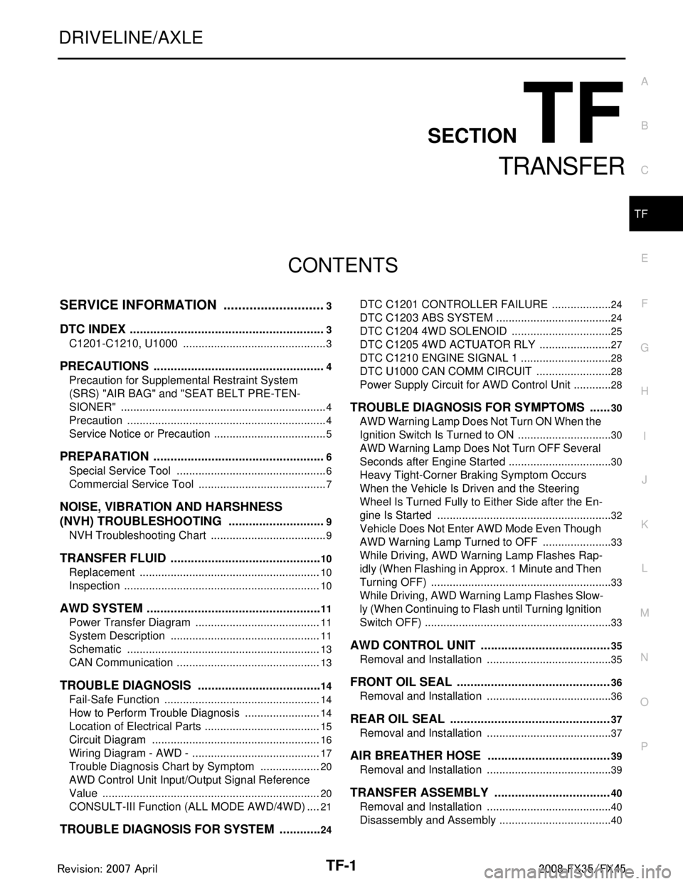
SERVICE INFORMATION .. ..........................3
DTC INDEX ..................................................... .....3
C1201-C1210, U1000 ......................................... ......3
PRECAUTIONS ...................................................4
Precaution for Supplemental Restraint System
(SRS) "AIR BAG" and "SEAT BELT PRE-TEN-
SIONER" ............................................................. ......
4
Precaution .................................................................4
Service Notice or Precaution .....................................5
PREPARATION ...................................................6
Special Service Tool ........................................... ......6
Commercial Service Tool ..........................................7
NOISE, VIBRATION AND HARSHNESS
(NVH) TROUBLESHOOTING .............................
9
NVH Troubleshooting Chart ................................ ......9
TRANSFER FLUID .............................................10
Replacement ....................................................... ....10
Inspection ................................................................10
AWD SYSTEM ................................................ ....11
Power Transfer Diagram ..................................... ....11
System Description .................................................11
Schematic ...............................................................13
CAN Communication ...............................................13
TROUBLE DIAGNOSIS .....................................14
Fail-Safe Function ............................................... ....14
How to Perform Trouble Diagnosis .........................14
Location of Electrical Parts ......................................15
Circuit Diagram .......................................................16
Wiring Diagram - AWD - ..........................................17
Trouble Diagnosis Chart by Symptom ....................20
AWD Control Unit Input/Output Signal Reference
Value ................................................................... ....
20
CONSULT-III Function (ALL MODE AWD/4WD) ....21
TROUBLE DIAGNOSIS FOR SYSTEM .............24
DTC C1201 CONTROLLER FAILURE ................ ....24
DTC C1203 ABS SYSTEM ......................................24
DTC C1204 4WD SOLENOID ............................. ....25
DTC C1205 4WD ACTUATOR RLY ........................27
DTC C1210 ENGINE SIGNAL 1 ..............................28
DTC U1000 CAN COMM CIRCUIT .........................28
Power Supply Circuit for AWD Control Unit .............28
TROUBLE DIAGNOSIS FOR SYMPTOMS ......30
AWD Warning Lamp Does Not Turn ON When the
Ignition Switch Is Turned to ON ...............................
30
AWD Warning Lamp Does Not Turn OFF Several
Seconds after Engine Started ..................................
30
Heavy Tight-Corner Braking Symptom Occurs
When the Vehicle Is Driven and the Steering
Wheel Is Turned Fully to Either Side after the En-
gine Is Started .........................................................
32
Vehicle Does Not Enter AWD Mode Even Though
AWD Warning Lamp Turned to OFF .......................
33
While Driving, AWD Warning Lamp Flashes Rap-
idly (When Flashing in Approx. 1 Minute and Then
Turning OFF) ....................................................... ....
33
While Driving, AWD Warning Lamp Flashes Slow-
ly (When Continuing to Flash until Turning Ignition
Switch OFF) .............................................................
33
AWD CONTROL UNIT ......................................35
Removal and Installation .........................................35
FRONT OIL SEAL .............................................36
Removal and Installation .........................................36
REAR OIL SEAL ...............................................37
Removal and Installation .........................................37
AIR BREATHER HOSE ....................................39
Removal and Installation .........................................39
TRANSFER ASSEMBLY ..................................40
Removal and Installation .........................................40
Disassembly and Assembly .....................................40
3AA93ABC3ACD3AC03ACA3AC03AC63AC53A913A773A893A873A873A8E3A773A983AC73AC93AC03AC3
3A893A873A873A8F3A773A9D3AAF3A8A3A8C3A863A9D3AAF3A8B3A8C
Page 3791 of 3924
PRECAUTIONSTF-5
< SERVICE INFORMATION >
CEF
G H
I
J
K L
M A
B
TF
N
O P
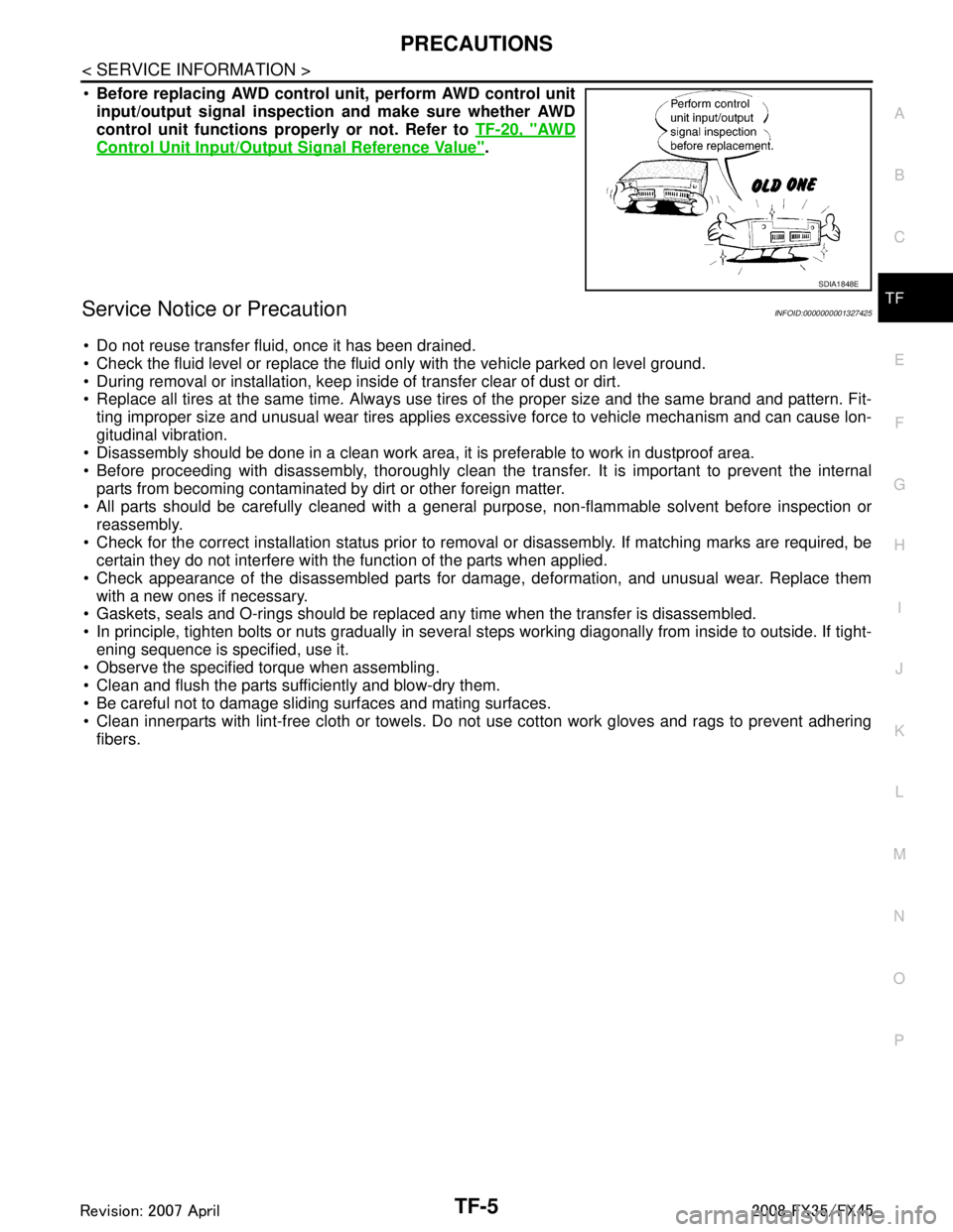
Before replacing AWD control unit, perform AWD control unit
input/output signal inspection and make sure whether AWD
control unit functions properly or not. Refer to TF-20, "
AW D
Control Unit Input/Output Signal Reference Value".
Service Notice or PrecautionINFOID:0000000001327425
Do not reuse transfer fluid, once it has been drained.
Check the fluid level or replace the fluid only with the vehicle parked on level ground.
During removal or installation, keep inside of transfer clear of dust or dirt.
Replace all tires at the same time. Always use tires of the proper size and the same brand and pattern. Fit-
ting improper size and unusual wear tires applies excessive force to vehicle mechanism and can cause lon-
gitudinal vibration.
Disassembly should be done in a clean work area, it is preferable to work in dustproof area.
Before proceeding with disassembly, thoroughly clean the tr ansfer. It is important to prevent the internal
parts from becoming contaminated by dirt or other foreign matter.
All parts should be carefully cleaned with a general purpose, non-flammable solvent before inspection or
reassembly.
Check for the correct installation status prior to remo val or disassembly. If matching marks are required, be
certain they do not interfere with t he function of the parts when applied.
Check appearance of the disassembled parts for dam age, deformation, and unusual wear. Replace them
with a new ones if necessary.
Gaskets, seals and O-rings should be replaced any time when the transfer is disassembled.
In principle, tighten bolts or nuts gradually in several steps working diagonally from inside to outside. If tight-
ening sequence is specified, use it.
Observe the specified torque when assembling.
Clean and flush the parts sufficiently and blow-dry them.
Be careful not to damage sliding surfaces and mating surfaces.
Clean innerparts with lint-free cloth or towels. Do not use cotton work gloves and rags to prevent adhering
fibers.
SDIA1848E
3AA93ABC3ACD3AC03ACA3AC03AC63AC53A913A773A893A873A873A8E3A773A983AC73AC93AC03AC3
3A893A873A873A8F3A773A9D3AAF3A8A3A8C3A863A9D3AAF3A8B3A8C
Page 3792 of 3924
TF-6
< SERVICE INFORMATION >
PREPARATION
PREPARATION
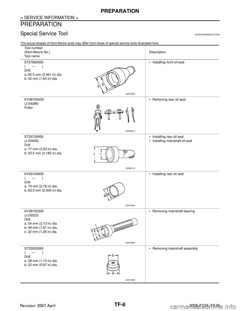
Special Service ToolINFOID:0000000001327426
The actual shapes of Kent-Moore tools may differ from those of special service tools illustrated here.
Tool number
(Kent-Moore No.)
Tool name Description
ST27862000
(—)
Drift
a: 62.5 mm (2.461 in) dia.
b: 42 mm (1.65 in) dia. Installing front oil seal
KV381054S0
(J-34286)
Puller Removing rear oil seal
ST30720000
(J-25405)
Drift
a: 77 mm (3.03 in) dia.
b: 55.5 mm (2.185 in) dia. Installing rear oil seal
Installing mainshaft oil seal
KV40104830
(—)
Drift
a: 70 mm (2.76 in) dia.
b: 63.5 mm (2.500 in) dia. Installing rear oil seal
KV38100300
(J-25523)
Drift
a: 54 mm (2.13 in) dia.
b: 46 mm (1.81 in) dia.
c: 32 mm (1.26 in) dia. Removing mainshaft bearing
ST33052000
(—)
Drift
a: 28 mm (1.10 in) dia.
b: 22 mm (0.87 in) dia. Removing mainshaft assembly
ZZA0194D
ZZA0601D
ZZA0811D
ZZA1003D
ZZA1046D
ZZA1000D
3AA93ABC3ACD3AC03ACA3AC03AC63AC53A913A773A893A873A873A8E3A773A983AC73AC93AC03AC3
3A893A873A873A8F3A773A9D3AAF3A8A3A8C3A863A9D3AAF3A8B3A8C
Page 3795 of 3924
NOISE, VIBRATION AND HARSHNESS (NVH) TROUBLESHOOTINGTF-9
< SERVICE INFORMATION >
CEF
G H
I
J
K L
M A
B
TF
N
O P
NOISE, VIBRATION AND HARSHN ESS (NVH) TROUBLESHOOTING
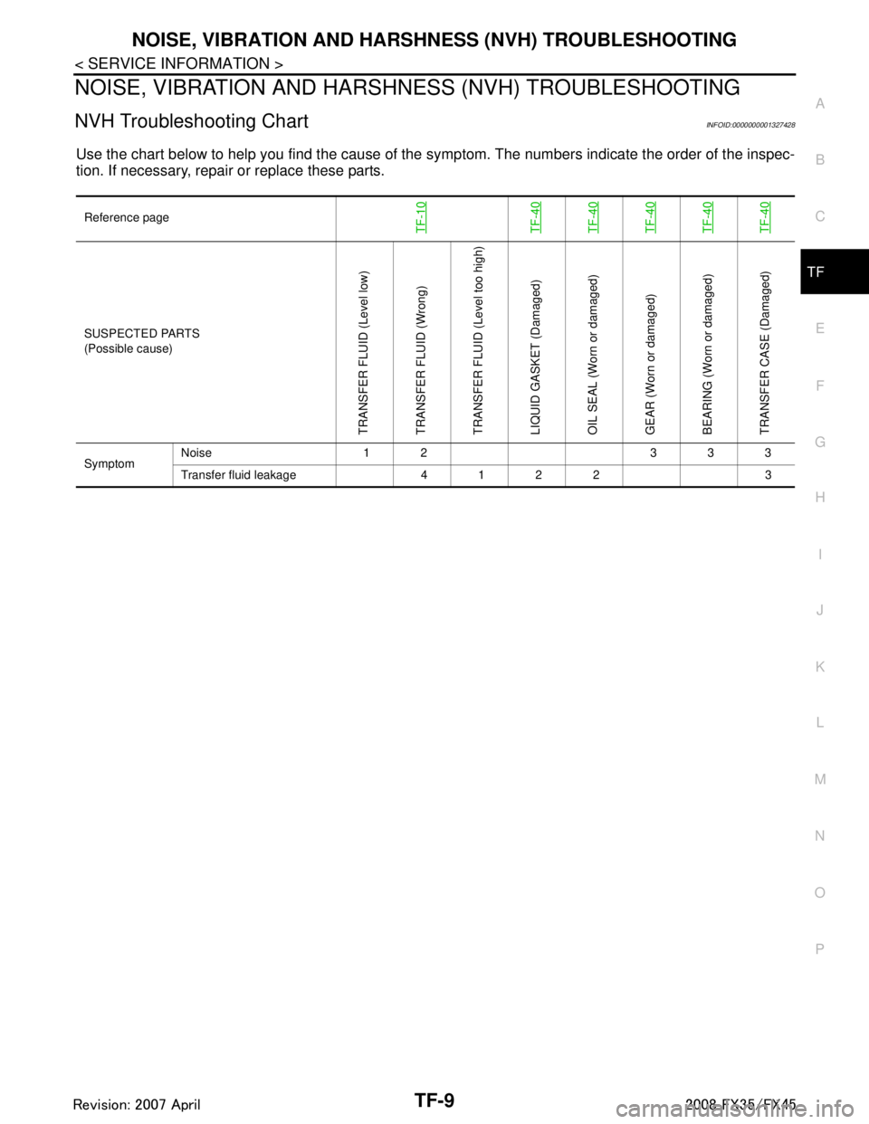
NVH Troubleshooting ChartINFOID:0000000001327428
Use the chart below to help you find the cause of the symptom. The numbers indicate the order of the inspec-
tion. If necessary, repair or replace these parts.
Reference pageTF-10TF-40TF-40TF-40TF-40TF-40
SUSPECTED PARTS
(Possible cause)
TRANSFER FLUID (Level low)
TRANSFER FLUID (Wrong)
TRANSFER FLUID (Level too high)
LIQUID GASKET (Damaged)
OIL SEAL (Worn or damaged)
GEAR (Worn or damaged)
BEARING (Worn or damaged)
TRANSFER CASE (Damaged)
Symptom Noise 1 2 3 3 3
Transfer fluid leakage 4 1 2 2 3
3AA93ABC3ACD3AC03ACA3AC03AC63AC53A913A773A893A873A873A8E3A773A983AC73AC93AC03AC3
3A893A873A873A8F3A773A9D3AAF3A8A3A8C3A863A9D3AAF3A8B3A8C