Page 3545 of 3924
PREPARATIONRFD-3
< SERVICE INFORMATION >
CEF
G H
I
J
K L
M A
B
RFD
N
O P
PREPARATION
Special Service ToolINFOID:0000000001327491
The actual shapes of Kent-Moore t ools may differ from those of special service tools illustrated here.
Tool number
(Kent-Moore No.)
Tool name Description
KV381054S0
(J-34286)
Puller Removing front oil seal
ST30720000
(J-25405)
Drift
a: 77 mm (3.03 in) dia.
b: 55.5 mm (2.185 in) dia. Installing front oil seal
Installing pinion rear bearing outer race
KV40104100
(—)
Attachment Removing side flange (For VQ35DE models)
KV40101000
(—)
Attachment Removing side flange (For VK45DE models)
ST36230000
(J-25840-A)
Sliding hammer Removing side flange
KV38100200
(J-26233)
Drift
a: 65 mm (2.56 in) dia.
b: 49 mm (1.93 in) dia. Installing side oil seal
ZZA0601D
ZZA0811D
ZZA0804D
NT159
ZZA0803D
ZZA1143D
3AA93ABC3ACD3AC03ACA3AC03AC63AC53A913A773A893A873A873A8E3A773A983AC73AC93AC03AC3
3A893A873A873A8F3A773A9D3AAF3A8A3A8C3A863A9D3AAF3A8B3A8C
Page 3546 of 3924
RFD-4
< SERVICE INFORMATION >
PREPARATION
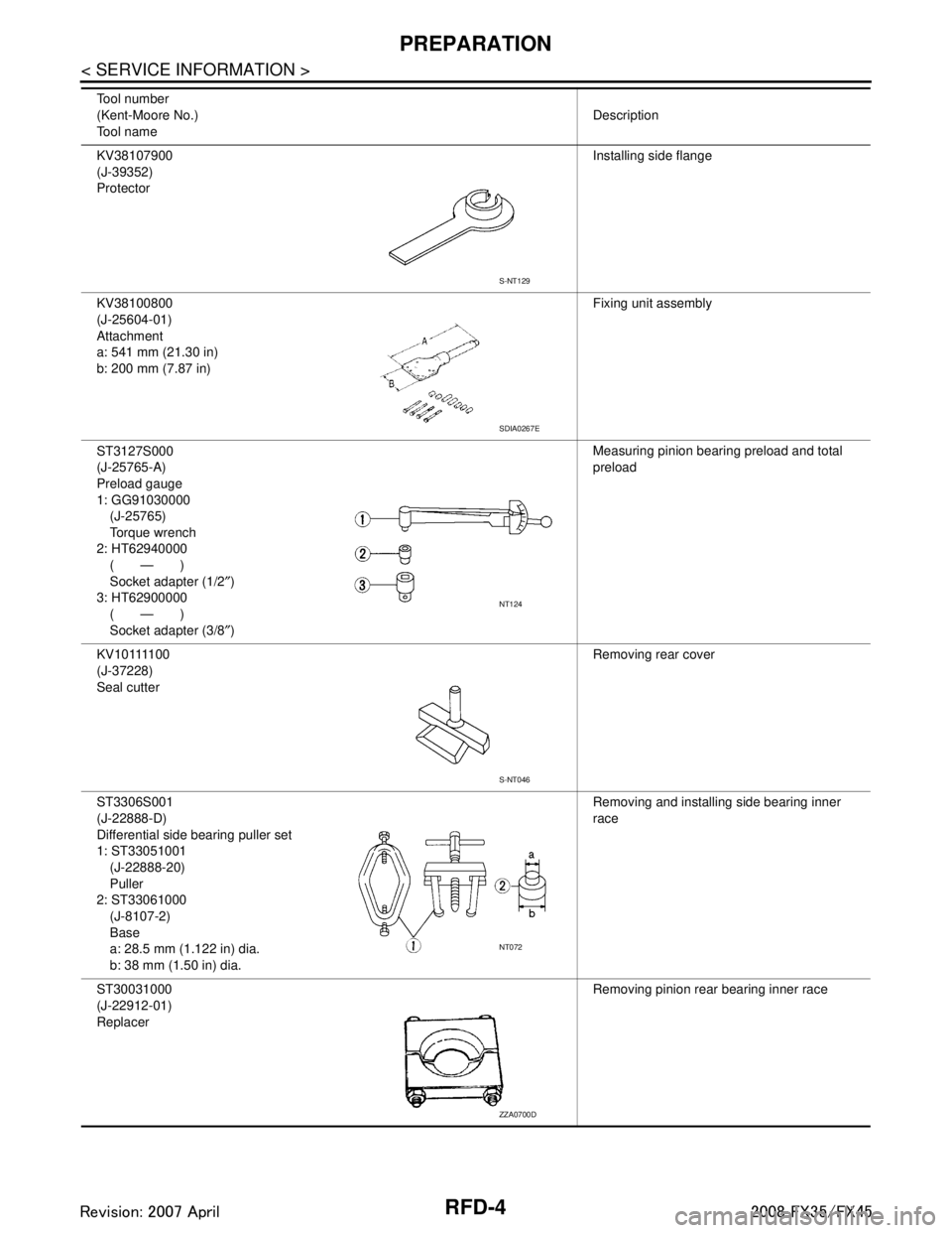
KV38107900
(J-39352)
ProtectorInstalling side flange
KV38100800
(J-25604-01)
Attachment
a: 541 mm (21.30 in)
b: 200 mm (7.87 in) Fixing unit assembly
ST3127S000
(J-25765-A)
Preload gauge
1: GG91030000 (J-25765)
Torque wrench
2: HT62940000 (—)
Socket adapter (1/2 ″)
3: HT62900000 (—)
Socket adapter (3/8 ″) Measuring pinion bearing preload and total
preload
K V 1 0 1111 0 0
(J-37228)
Seal cutter Removing rear cover
ST3306S001
(J-22888-D)
Differential side bearing puller set
1: ST33051001 (J-22888-20)
Puller
2: ST33061000 (J-8107-2)
Base
a: 28.5 mm (1.122 in) dia.
b: 38 mm (1.50 in) dia. Removing and installing side bearing inner
race
ST30031000
(J-22912-01)
Replacer Removing pinion rear bearing inner race
Tool number
(Kent-Moore No.)
Tool name
Description
S-NT129
SDIA0267E
NT124
S-NT046
NT072
ZZA0700D
3AA93ABC3ACD3AC03ACA3AC03AC63AC53A913A773A893A873A873A8E3A773A983AC73AC93AC03AC3
3A893A873A873A8F3A773A9D3AAF3A8A3A8C3A863A9D3AAF3A8B3A8C
Page 3552 of 3924
RFD-10
< SERVICE INFORMATION >
FRONT OIL SEAL
FRONT OIL SEAL
Removal and InstallationINFOID:0000000001327497
CAUTION:
Verify identification stamp of replacement frequency put in the lower part of gear carrier to determine
replacement for collapsible spacer when replacing front oil seal. Refer to "IDENTIFICATION STAMP OF
REPLACEMENT FREQUENCY OF FRONT OIL SEAL". If necessary collapsible spacer replacement,
remove final drive assembly and disassemble it to re place front oil seal and collapsible spacer. Refer
to RFD-16, "
Removal and Installation" and RFD-17, "Disassembly and Assembly".
NOTE:
The reuse of collapsible spacer is pr ohibited in principle. However, it is reusable on a one-time basis
only in cases when replacing front oil seal.
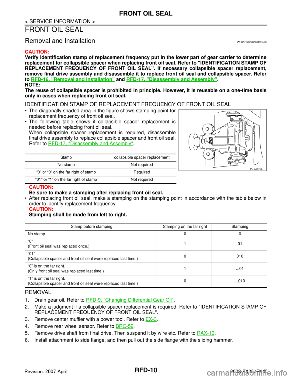
IDENTIFICATION STAMP OF REPLACEMENT FREQUENCY OF FRONT OIL SEAL
The diagonally shaded area in the figure shows stamping point for replacement frequency of front oil seal.
The following table shows if collapsible spacer replacement is needed before replacing front oil seal.
When collapsible spacer replacement is required, disassemble
final drive assembly to replace collapsible spacer and front oil seal.
Refer to RFD-17, "
Disassembly and Assembly".
CAUTION:
Be sure to make a stamping after replacing front oil seal.
After replacing front oil seal, make a stamping on the stamping point in accordance with the table below in order to identify replacement frequency.
CAUTION:
Stamping shall be made from left to right.
REMOVAL
1. Drain gear oil. Refer to RFD-9, "Changing Differential Gear Oil".
2. Make a judgment if a collapsible spacer replacement is required. Refer to "IDENTIFICATION STAMP OF REPLACEMENT FREQUENCY OF FRONT OIL SEAL".
3. Remove center muffler with a power tool. Refer to EX-3
.
4. Remove rear wheel sensor. Refer to BRC-52
.
5. Remove drive shaft from final drive. Then suspend it by wire etc. Refer to RAX-10
.
6. Install attachment to side flange, and then pull out the side flange with the sliding hammer.
Stamp collapsible spacer replacement
No stamp Not required
“0” or “0” on the far right of stamp Required
“01” or “1” on the far ri ght of stamp Not required
PDIA0976E
Stamp before stamping Stamping on the far right Stamping
No stamp 00
“0”
(Front oil seal was replaced once.) 101
“01”
(Collapsible spacer and front oil seal were replaced last time.) 0010
“0” is on the far right.
(Only front oil seal was replaced last time.) 1 ...01
“1” is on the far right.
(Collapsible spacer and front oil seal were replaced last time.) 0...010
3AA93ABC3ACD3AC03ACA3AC03AC63AC53A913A773A893A873A873A8E3A773A983AC73AC93AC03AC3
3A893A873A873A8F3A773A9D3AAF3A8A3A8C3A863A9D3AAF3A8B3A8C
Page 3553 of 3924
FRONT OIL SEALRFD-11
< SERVICE INFORMATION >
CEF
G H
I
J
K L
M A
B
RFD
N
O P
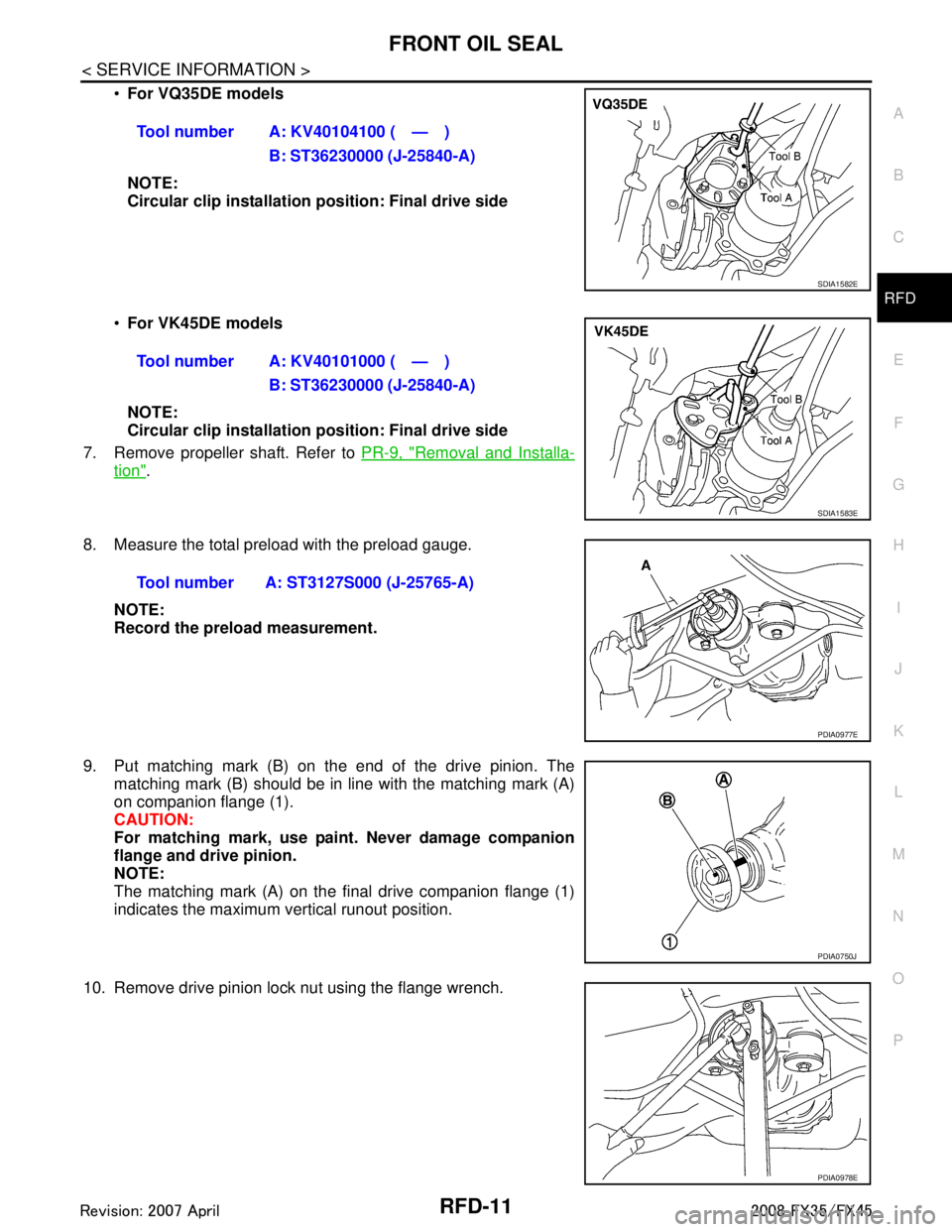
For VQ35DE models
NOTE:
Circular clip installation position: Final drive side
For VK45DE models
NOTE:
Circular clip installation position: Final drive side
7. Remove propeller shaft. Refer to PR-9, "
Removal and Installa-
tion".
8. Measure the total preload with the preload gauge. NOTE:
Record the preload measurement.
9. Put matching mark (B) on the end of the drive pinion. The matching mark (B) should be in line with the matching mark (A)
on companion flange (1).
CAUTION:
For matching mark, use pain t. Never damage companion
flange and drive pinion.
NOTE:
The matching mark (A) on the final drive companion flange (1)
indicates the maximum vertical runout position.
10. Remove drive pinion lock nut using the flange wrench. Tool number A: KV40104100 ( — )
B: ST36230000 (J-25840-A)
SDIA1582E
Tool number A: KV40101000 ( — )B: ST36230000 (J-25840-A)
SDIA1583E
Tool number A: ST3127S000 (J-25765-A)
PDIA0977E
PDIA0750J
PDIA0978E
3AA93ABC3ACD3AC03ACA3AC03AC63AC53A913A773A893A873A873A8E3A773A983AC73AC93AC03AC3
3A893A873A873A8F3A773A9D3AAF3A8A3A8C3A863A9D3AAF3A8B3A8C
Page 3554 of 3924
RFD-12
< SERVICE INFORMATION >
FRONT OIL SEAL
11. Remove companion flange using a puller.
12. Remove front oil seal using the puller.
INSTALLATION
1. Apply multi-purpose grease to front oil seal lips.
2. Install front oil seal using the drift as shown in figure.CAUTION:
Never reuse oil seal.
When installing, n ever incline oil seal.
3. Align the matching mark (B) of drive pinion with the matching mark (A) of companion flange (1), and then install the compan-
ion flange (1).
4. Apply anti-corrosion oil to the thread and seat of new drive pinion lock nut, and temporarily tighten drive
pinion lock nut to drive pinion.
CAUTION:
Never reuse drive pinion lock nut.
PDIA0979E
Tool number A: KV381054S0 (J-34286)
PDIA0980E
Tool number A: ST30720000 (J-25405)
PDIA0752J
PDIA0750J
3AA93ABC3ACD3AC03ACA3AC03AC63AC53A913A773A893A873A873A8E3A773A983AC73AC93AC03AC3
3A893A873A873A8F3A773A9D3AAF3A8A3A8C3A863A9D3AAF3A8B3A8C
Page 3555 of 3924
FRONT OIL SEALRFD-13
< SERVICE INFORMATION >
CEF
G H
I
J
K L
M A
B
RFD
N
O P
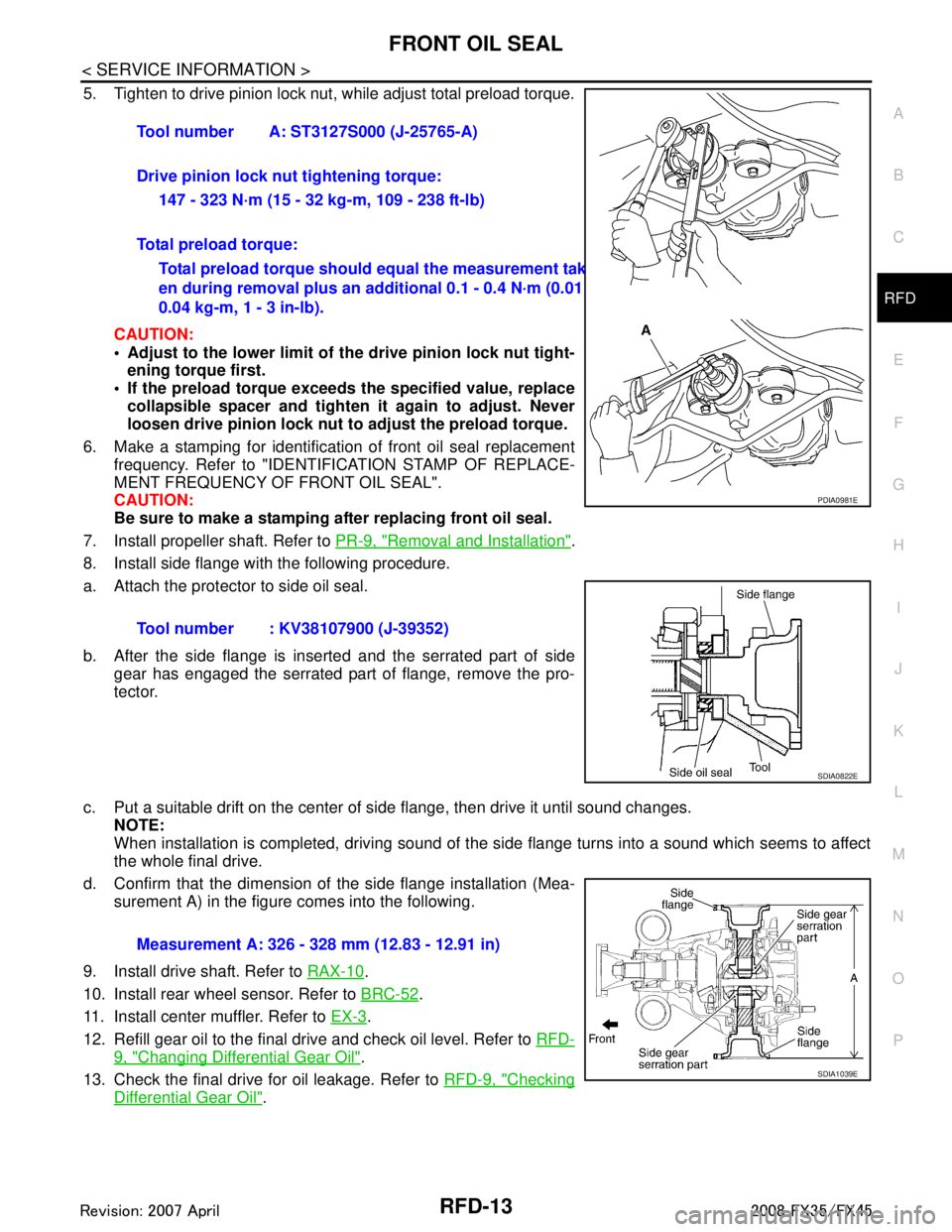
5. Tighten to drive pinion lock nut, while adjust total preload torque.
CAUTION:
Adjust to the lower limit of the drive pinion lock nut tight-
ening torque first.
If the preload torque exceeds the specified value, replace
collapsible spacer and tighte n it again to adjust. Never
loosen drive pinion lock nut to adjust the preload torque.
6. Make a stamping for identificati on of front oil seal replacement
frequency. Refer to "IDENTIFICATION STAMP OF REPLACE-
MENT FREQUENCY OF FRONT OIL SEAL".
CAUTION:
Be sure to make a stamping after replacing front oil seal.
7. Install propeller shaft. Refer to PR-9, "
Removal and Installation".
8. Install side flange with the following procedure.
a. Attach the protector to side oil seal.
b. After the side flange is inserted and the serrated part of side gear has engaged the serrated part of flange, remove the pro-
tector.
c. Put a suitable drift on the center of side flange, then drive it until sound changes.
NOTE:
When installation is completed, driving sound of the side flange turns into a sound which seems to affect
the whole final drive.
d. Confirm that the dimension of the side flange installation (Mea- surement A) in the figure comes into the following.
9. Install drive shaft. Refer to RAX-10
.
10. Install rear wheel sensor. Refer to BRC-52
.
11. Install center muffler. Refer to EX-3
.
12. Refill gear oil to the final drive and check oil level. Refer to RFD-
9, "Changing Differential Gear Oil".
13. Check the final drive for oil leakage. Refer to RFD-9, "
Checking
Differential Gear Oil".
Tool number A: ST3127S000 (J-25765-A)
Drive pinion lock nut tightening torque:
147 - 323 N·m (15 - 32 kg-m, 109 - 238 ft-lb)
Total preload torque: Total preload torque should equal the measurement tak-
en during removal plus an ad ditional 0.1 - 0.4 N·m (0.01 -
0.04 kg-m, 1 - 3 in-lb).
Tool number : KV38107900 (J-39352)
PDIA0981E
SDIA0822E
Measurement A: 326 - 328 mm (12.83 - 12.91 in)
SDIA1039E
3AA93ABC3ACD3AC03ACA3AC03AC63AC53A913A773A893A873A873A8E3A773A983AC73AC93AC03AC3
3A893A873A873A8F3A773A9D3AAF3A8A3A8C3A863A9D3AAF3A8B3A8C
Page 3556 of 3924
RFD-14
< SERVICE INFORMATION >
SIDE OIL SEAL
SIDE OIL SEAL
Removal and InstallationINFOID:0000000001327498
REMOVAL
1. Remove center muffler with a power tool. Refer to EX-3.
2. Remove rear wheel sensor. Refer to BRC-52
.
3. Remove drive shaft from final drive. Then suspend it by wire etc. Refer to RAX-10
.
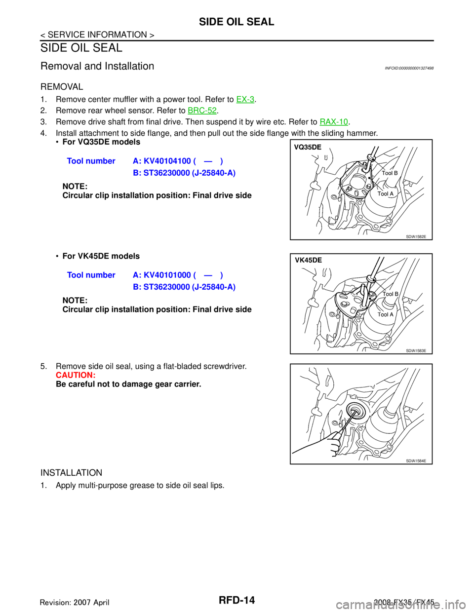
4. Install attachment to side flange, and then pull out the side flange with the sliding hammer.
For VQ35DE models
NOTE:
Circular clip installation position: Final drive side
For VK45DE models
NOTE:
Circular clip installation position: Final drive side
5. Remove side oil seal, using a flat-bladed screwdriver. CAUTION:
Be careful not to damage gear carrier.
INSTALLATION
1. Apply multi-purpose grease to side oil seal lips. Tool number A: KV40104100 ( — )
B: ST36230000 (J-25840-A)
SDIA1582E
Tool number A: KV40101000 ( — )B: ST36230000 (J-25840-A)
SDIA1583E
SDIA1584E
3AA93ABC3ACD3AC03ACA3AC03AC63AC53A913A773A893A873A873A8E3A773A983AC73AC93AC03AC3
3A893A873A873A8F3A773A9D3AAF3A8A3A8C3A863A9D3AAF3A8B3A8C
Page 3557 of 3924
SIDE OIL SEALRFD-15
< SERVICE INFORMATION >
CEF
G H
I
J
K L
M A
B
RFD
N
O P
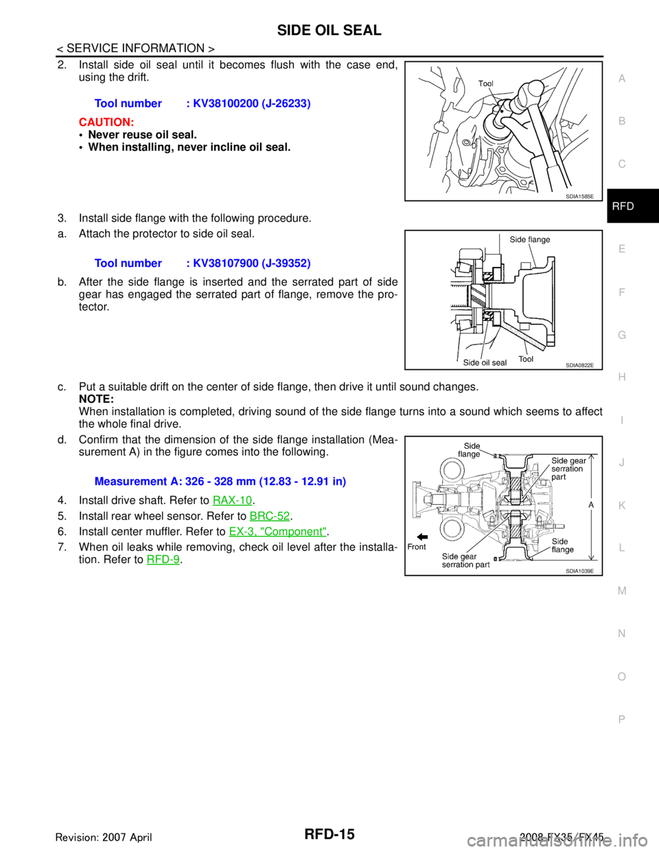
2. Install side oil seal until it becomes flush with the case end, using the drift.
CAUTION:
Never reuse oil seal.
When installing, never incline oil seal.
3. Install side flange with the following procedure.
a. Attach the protector to side oil seal.
b. After the side flange is inserted and the serrated part of side gear has engaged the serrated part of flange, remove the pro-
tector.
c. Put a suitable drift on the center of side flange, then drive it until sound changes.
NOTE:
When installation is completed, driving sound of the side flange turns into a sound which seems to affect
the whole final drive.
d. Confirm that the dimension of the side flange installation (Mea- surement A) in the figure comes into the following.
4. Install drive shaft. Refer to RAX-10
.
5. Install rear wheel sensor. Refer to BRC-52
.
6. Install center muffler. Refer to EX-3, "
Component".
7. When oil leaks while removing, check oil level after the installa- tion. Refer to RFD-9
.
Tool number : KV38100200 (J-26233)
SDIA1585E
Tool number : KV38107900 (J-39352)
SDIA0822E
Measurement A: 326 - 328 mm (12.83 - 12.91 in)
SDIA1039E
3AA93ABC3ACD3AC03ACA3AC03AC63AC53A913A773A893A873A873A8E3A773A983AC73AC93AC03AC3
3A893A873A873A8F3A773A9D3AAF3A8A3A8C3A863A9D3AAF3A8B3A8C