2008 INFINITI FX35 seal
[x] Cancel search: sealPage 3560 of 3924
RFD-18
< SERVICE INFORMATION >
REAR FINAL DRIVE ASSEMBLY
ASSEMBLY INSPECTION AND ADJUSTMENT
Before inspection and adjustment, drain gear oil.
Total Preload Torque
1. Secure final drive assembly onto an attachment.
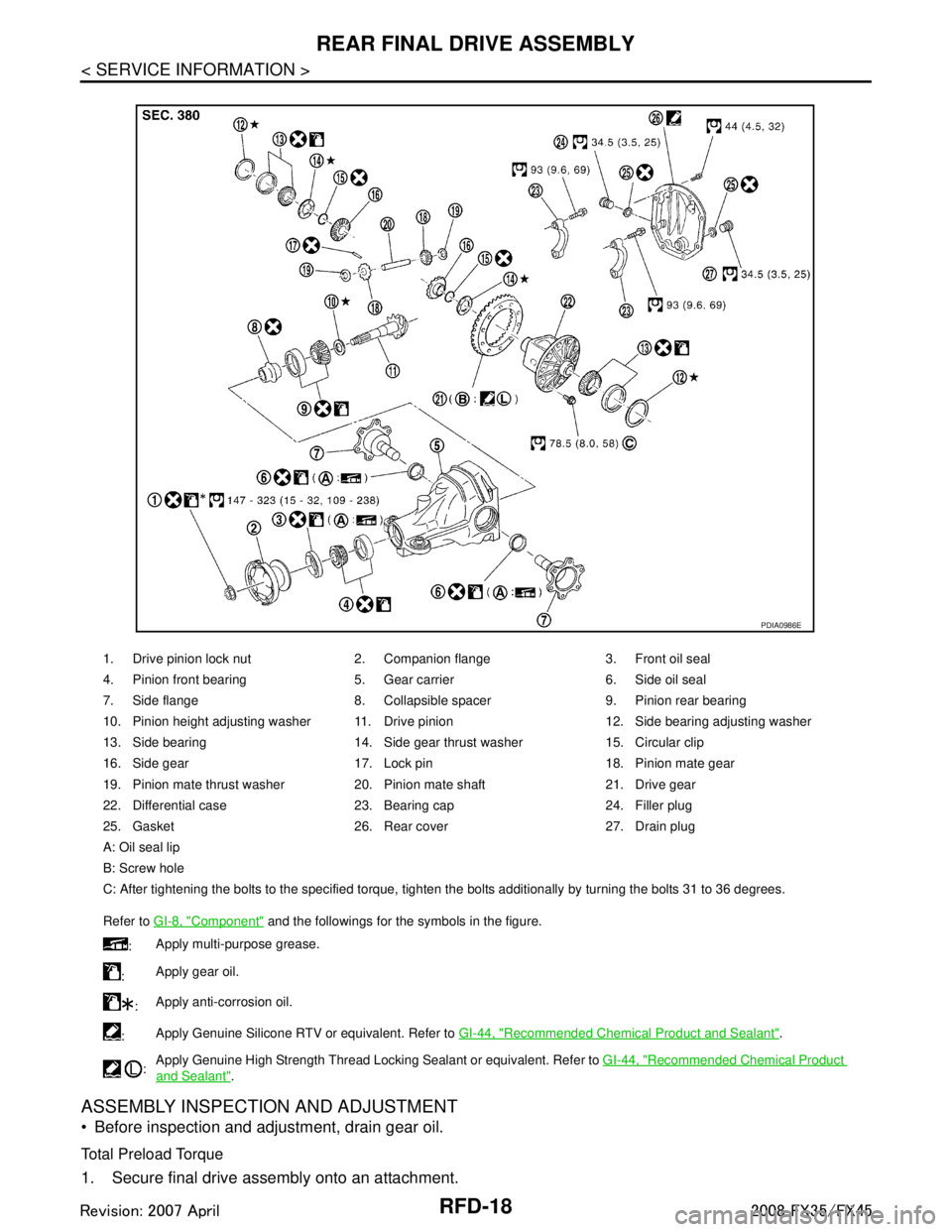
1. Drive pinion lock nut 2. Companion flange 3. Front oil seal
4. Pinion front bearing 5. Gear carrier 6. Side oil seal
7. Side flange 8. Collapsible spacer 9. Pinion rear bearing
10. Pinion height adjusting washer 11. Drive pinion 12. Side bearing adjusting washer
13. Side bearing 14. Side gear thrust washer 15. Circular clip
16. Side gear 17. Lock pin 18. Pinion mate gear
19. Pinion mate thrust washer 20. Pinion mate shaft 21. Drive gear
22. Differential case 23. Bearing cap 24. Filler plug
25. Gasket 26. Rear cover 27. Drain plug
A: Oil seal lip
B: Screw hole
C: After tightening the bolts to the specified torque, tighten the bolts additionally by turning the bolts 31 to 36 degrees.
Refer to GI-8, "
Component" and the followings for the symbols in the figure.
: Apply multi-purpose grease.
: Apply gear oil.
: Apply anti-corrosion oil.
: Apply Genuine Silicone RTV or equivalent. Refer to
GI-44, "
Recommended Chemical Product and Sealant".
: Apply Genuine High Strength Thread Locking Sealant or equivalent. Refer to
GI-44, "
Recommended Chemical Product
and Sealant".
PDIA0986E
3AA93ABC3ACD3AC03ACA3AC03AC63AC53A913A773A893A873A873A8E3A773A983AC73AC93AC03AC3
3A893A873A873A8F3A773A9D3AAF3A8A3A8C3A863A9D3AAF3A8B3A8C
Page 3564 of 3924

RFD-22
< SERVICE INFORMATION >
REAR FINAL DRIVE ASSEMBLY
Never change the total amount of washers as it will change the bearing preload.
Companion Flange Runout
1. Fit a test indicator to the inner side of companion flange (socket
diameter).
2. Rotate companion flange to check for runout.
3. If the runout value is outside t he runout limit, follow the proce-
dure below to adjust.
a. Check for runout while changing the phase between companion flange and drive pinion by 90 ° step, and search for the position
where the runout is the minimum.
b. If the runout value is still outside of the limit after the phase has been changed, possible cause will be an assembly malfunction of drive pinion and pinion bearing and
malfunction of pinion bearing. Check for these items and repair if necessary.
c. If the runout value is still outside of the limit after the check and repair, replace companion flange.
DISASSEMBLY
Differential Assembly
1. Drain gear oil, if necessary.
2. Remove side flange.
3. Remove rear cover mounting bolts.
4. Remove rear cover to insert the seal cutter between gear carrier and rear cover.
CAUTION:
Be careful not to damage the mating surface.
Never insert flat-bladed screwdriver, this way damage the
mating surface.
5. Using two 45 mm (1.77 in) spacers, mount carrier on the attach- ment.Runout limit: 0.08 mm (0.0031 in)
PDIA0490E
Tool number A: KV10111100 (J-37228)
PDIA0756J
Tool number A: KV38100800 (J-25604-01)
PDIA0757J
3AA93ABC3ACD3AC03ACA3AC03AC63AC53A913A773A893A873A873A8E3A773A983AC73AC93AC03AC3
3A893A873A873A8F3A773A9D3AAF3A8A3A8C3A863A9D3AAF3A8B3A8C
Page 3568 of 3924
RFD-26
< SERVICE INFORMATION >
REAR FINAL DRIVE ASSEMBLY
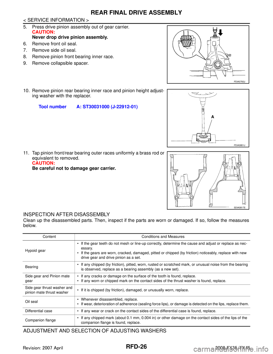
5. Press drive pinion assembly out of gear carrier.CAUTION:
Never drop drive pinion assembly.
6. Remove front oil seal.
7. Remove side oil seal.
8. Remove pinion front bearing inner race.
9. Remove collapsible spacer.
10. Remove pinion rear bearing inner race and pinion height adjust- ing washer with the replacer.
11. Tap pinion front/rear bearing outer races uniformly a brass rod or equivalent to removed.
CAUTION:
Be careful not to damage gear carrier.
INSPECTION AFTER DISASSEMBLY
Clean up the disassembled parts. Then, inspect if the parts are worn or damaged. If so, follow the measures
below.
ADJUSTMENT AND SELECTION OF ADJUSTING WASHERS
PDIA0760J
Tool number A: ST30031000 (J-22912-01)
PDIA0801J
SDIA0817E
Content Conditions and Measures
Hypoid gear If the gear teeth do not mesh or line-up correctly, determine the cause and adjust or replace as nec-
essary.
If the gears are worn, cracked, damaged, pitted or chipped (by friction) noticeably, replace with new drive gear and drive pinion as a set.
Bearing If any chipped (by friction), pitted, worn, rusted or scratched mark, or unusual noise from the bearing
is observed, replace as a bearing assembly (as a new set).
Side gear and Pinion mate
gear If any cracks or damage on the surface of the tooth is found, replace.
If any worn or chipped mark on the contact sides of the thrust washer is found, replace.
Side gear thrust washer and
pinion mate thrust washer If it is chipped (by friction), damaged, or unusually worn, replace.
Oil seal Whenever disassembled, replace.
If wear, deterioration of adherence (sealing force lips), or damage is detected on the lips, replace them.
Differential case If any wear or crack on the contact sides of the differential case is found, replace.
Companion flange If any chipped mark (about 0.1 mm, 0.004 in) or other damage on the contact sides of the lips of the
companion flange is found, replace.
3AA93ABC3ACD3AC03ACA3AC03AC63AC53A913A773A893A873A873A8E3A773A983AC73AC93AC03AC3
3A893A873A873A8F3A773A9D3AAF3A8A3A8C3A863A9D3AAF3A8B3A8C
Page 3575 of 3924
REAR FINAL DRIVE ASSEMBLYRFD-33
< SERVICE INFORMATION >
CEF
G H
I
J
K L
M A
B
RFD
N
O P
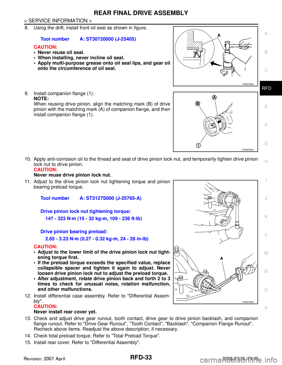
8. Using the drift, install front oil seal as shown in figure.
CAUTION:
Never reuse oil seal.
When installing, never incline oil seal.
Apply multi-purpose grease onto oil seal lips, and gear oilonto the circumference of oil seal.
9. Install companion flange (1). NOTE:
When reusing drive pinion, align the matching mark (B) of drive
pinion with the matching mark (A) of companion flange, and then
install companion flange (1).
10. Apply anti-corrosion oil to the thread and seat of drive pinion lock nut, and temporarily tighten drive pinion lock nut to drive pinion.
CAUTION:
Never reuse drive pinion lock nut.
11. Adjust to the drive pinion lock nut tightening torque and pinion bearing preload torque.
CAUTION:
Adjust to the lower limit of the drive pinion lock nut tight-
ening torque first.
If the preload torque exceeds the specified value, replace collapsible spacer and tighte n it again to adjust. Never
loosen drive pinion lock nut to adjust the preload torque.
After adjustment, rotate dri ve pinion back and forth 2 to 3
times to check for unusual no ise, rotation malfunction,
and other malfunctions.
12. Install differential case assembly. Refer to "Differential Assem- bly".
CAUTION:
Never install rear cover yet.
13. Check and adjust drive gear runout, tooth contact, drive gear to drive pinion backlash, and companion
flange runout. Refer to "Drive Gear Runout", "Tooth Contact", "Backlash", "Companion Flange Runout".
Recheck above items. Readjust the above description, if necessary.
14. Check total preload torque. Refer to "Total Preload Torque".
15. Install rear cover. Refer to "Differential Assembly". Tool number A: ST30720000 (J-25405)
PDIA0764J
PDIA0750J
Tool number A: ST3127S000 (J-25765-A)
Drive pinion lock nut tightening torque:
147 - 323 N·m (15 - 32 kg-m, 109 - 238 ft-lb)
Drive pinion bearing preload: 2.65 - 3.23 N·m (0.27 - 0.32 kg-m, 24 - 28 in-lb)
PDIA0765J
3AA93ABC3ACD3AC03ACA3AC03AC63AC53A913A773A893A873A873A8E3A773A983AC73AC93AC03AC3
3A893A873A873A8F3A773A9D3AAF3A8A3A8C3A863A9D3AAF3A8B3A8C
Page 3577 of 3924
REAR FINAL DRIVE ASSEMBLYRFD-35
< SERVICE INFORMATION >
CEF
G H
I
J
K L
M A
B
RFD
N
O P
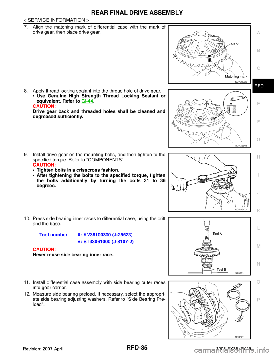
7. Align the matching mark of differential case with the mark of drive gear, then place drive gear.
8. Apply thread locking sealant into the thread hole of drive gear. Use Genuine High Strength Thread Locking Sealant or
equivalent. Refer to GI-44
.
CAUTION:
Drive gear back and threaded holes shall be cleaned and
degreased sufficiently.
9. Install drive gear on the mounting bolts, and then tighten to the specified torque. Refer to "COMPONENTS".
CAUTION:
Tighten bolts in a crisscross fashion.
After tightening the bolts to the specified torque, tighten
the bolts additionally by turning the bolts 31 to 36
degrees.
10. Press side bearing inner races to differential case, using the drift and the base.
CAUTION:
Never reuse side bearing inner race.
11. Install differential case assembly with side bearing outer races into gear carrier.
12. Measure side bearing preload. If necessary, select the appropri- ate side bearing adjusting washers. Refer to "Side Bearing Pre-
load".
SDIA2593E
SDIA2594E
SDIA0247J
Tool number A: KV38100300 (J-25523)
B: ST33061000 (J-8107-2)
SPD353
SPD527
3AA93ABC3ACD3AC03ACA3AC03AC63AC53A913A773A893A873A873A8E3A773A983AC73AC93AC03AC3
3A893A873A873A8F3A773A9D3AAF3A8A3A8C3A863A9D3AAF3A8B3A8C
Page 3578 of 3924
RFD-36
< SERVICE INFORMATION >
REAR FINAL DRIVE ASSEMBLY
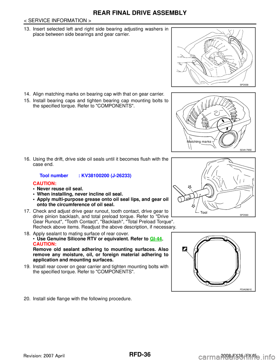
13. Insert selected left and right side bearing adjusting washers inplace between side bearings and gear carrier.
14. Align matching marks on bearing cap with that on gear carrier.
15. Install bearing caps and tighten bearing cap mounting bolts to the specified torque. Refer to "COMPONENTS".
16. Using the drift, drive side oil s eals until it becomes flush with the
case end.
CAUTION:
Never reuse oil seal.
When installing, n ever incline oil seal.
Apply multi-purpose grease onto oil seal lips, and gear oil
onto the circumference of oil seal.
17. Check and adjust drive gear runout, tooth contact, drive gear to drive pinion backlash, and total preload torque. Refer to "Drive
Gear Runout", "Tooth Contact", "Backlash", "Total Preload Torque".
Recheck above items. Readjust the above description, if necessary.
18. Apply sealant to mating surface of rear cover. Use Genuine Silicone RTV or equivalent. Refer to GI-44
.
CAUTION:
Remove old sealant adhering to mounting surfaces. Also
remove any moisture, oil, or foreign material adhering to
application and mounting surfaces.
19. Install rear cover on gear carrier and tighten mounting bolts with the specified torque. Refer to "COMPONENTS".
20. Install side flange with the following procedure.
SPD558
SDIA1795E
Tool number : KV38100200 (J-26233)
SPD560
PDIA0961E
3AA93ABC3ACD3AC03ACA3AC03AC63AC53A913A773A893A873A873A8E3A773A983AC73AC93AC03AC3
3A893A873A873A8F3A773A9D3AAF3A8A3A8C3A863A9D3AAF3A8B3A8C
Page 3579 of 3924
REAR FINAL DRIVE ASSEMBLYRFD-37
< SERVICE INFORMATION >
CEF
G H
I
J
K L
M A
B
RFD
N
O P
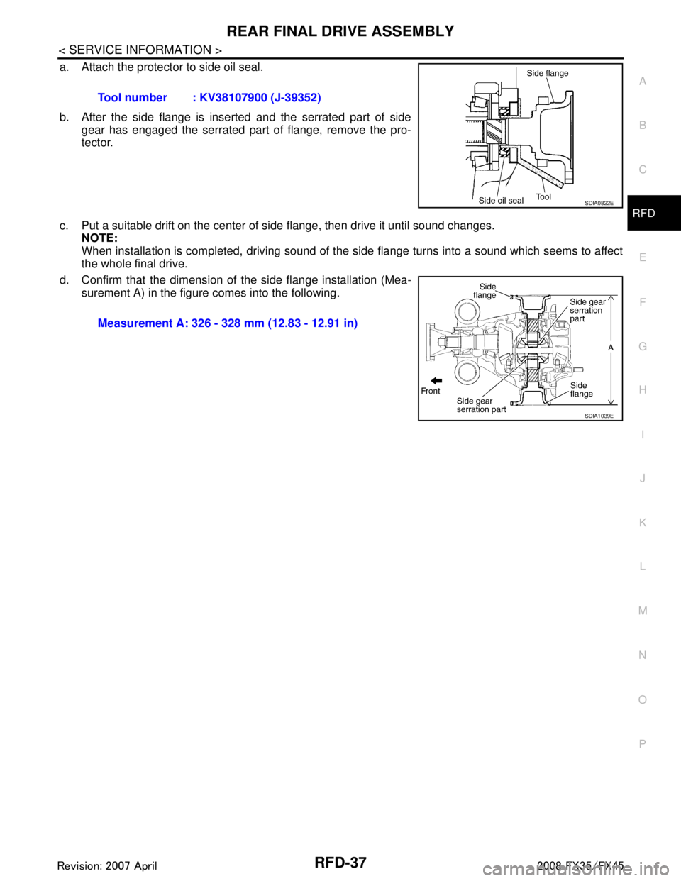
a. Attach the protector to side oil seal.
b. After the side flange is inserted and the serrated part of side gear has engaged the serrated part of flange, remove the pro-
tector.
c. Put a suitable drift on the center of side flange, then drive it until sound changes.
NOTE:
When installation is completed, driving sound of the side flange turns into a sound which seems to affect
the whole final drive.
d. Confirm that the dimension of the side flange installation (Mea- surement A) in the figure comes into the following.Tool number : KV38107900 (J-39352)
SDIA0822E
Measurement A: 326 - 328 mm (12.83 - 12.91 in)
SDIA1039E
3AA93ABC3ACD3AC03ACA3AC03AC63AC53A913A773A893A873A873A8E3A773A983AC73AC93AC03AC3
3A893A873A873A8F3A773A9D3AAF3A8A3A8C3A863A9D3AAF3A8B3A8C
Page 3588 of 3924

REAR SUSPENSION ASSEMBLYRSU-7
< SERVICE INFORMATION >
C
DF
G H
I
J
K L
M A
B
RSU
N
O P
1. Bushing 2. Mounting seal 3. Mounting seal bracket
4. Distance tube 5. Bound bumper cover 6. Bound bumper
7. Shock absorber 8. Upper seat 9. Coil spring
10. Rubber seat 11. Rear lower link 12. Axle assembly
13. Cotter pin 14. Radius rod 15. Front lower link protector
16. Front lower link 17. Stopper rubber 18. Shock absorber assembly
JPEIB0031GB
3AA93ABC3ACD3AC03ACA3AC03AC63AC53A913A773A893A873A873A8E3A773A983AC73AC93AC03AC3
3A893A873A873A8F3A773A9D3AAF3A8A3A8C3A863A9D3AAF3A8B3A8C