2008 INFINITI FX35 seal
[x] Cancel search: sealPage 3485 of 3924
PS-30
< SERVICE INFORMATION >
POWER STEERING OIL PUMP
DISASSEMBLY
NOTE:
Fix oil pump in vise as the occasion demands.
CAUTION:
When retaining drive shaft in a vise, always use copper or alumin um plates between vise and shaft.
1. Unscrew four rear cover bolts and remove rear cover from body assembly.
2. Remove rear side plate from cartridge, then re move Teflon ring and O-ring from rear side plate.
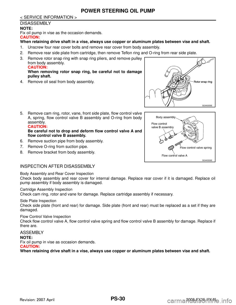
3. Remove rotor snap ring with snap ring pliers, and remove pulley from body assembly.
CAUTION:
When removing rotor snap ring, be careful not to damage
pulley shaft.
4. Remove oil seal from body assembly.
5. Remove cam ring, rotor, vane, front side plate, flow control valve A, spring, flow control valve B assembly and O-ring from body
assembly.
CAUTION:
Be careful not to drop and deform flow control valve A and
flow control valve B assembly.
6. Remove suction pipe from body assembly.
7. Remove O-ring from suction pipe.
8. Remove bracket from body assembly.
INSPECTION AFTER DISASSEMBLY
Body Assembly and Rear Cover Inspection
Check body assembly and rear cover for internal damage. Replace rear cover if it is damaged. Replace oil
pump assembly if body assembly is damaged.
Cartridge Assembly Inspection
Check cam ring, rotor and vane for damage. Replace cartridge assembly if necessary.
Side Plate Inspection
Check side plate (front and rear) for damage. Side plate (f ront and rear) must be replaced as a set if they are
damaged.
Flow Control Valve Inspection
Check flow control valve A, flow control valve spring and flow control valve B assembly for damage. Replace if
there are.
ASSEMBLY
NOTE:
Fix oil pump in vise as occasion demands.
CAUTION:
When retaining drive shaft in a vise, always use copper or alumin um plates between vise and shaft.
SGIA0059E
SGIA0526E
3AA93ABC3ACD3AC03ACA3AC03AC63AC53A913A773A893A873A873A8E3A773A983AC73AC93AC03AC3
3A893A873A873A8F3A773A9D3AAF3A8A3A8C3A863A9D3AAF3A8B3A8C
Page 3486 of 3924
POWER STEERING OIL PUMPPS-31
< SERVICE INFORMATION >
C
DE
F
H I
J
K L
M A
B
PS
N
O P
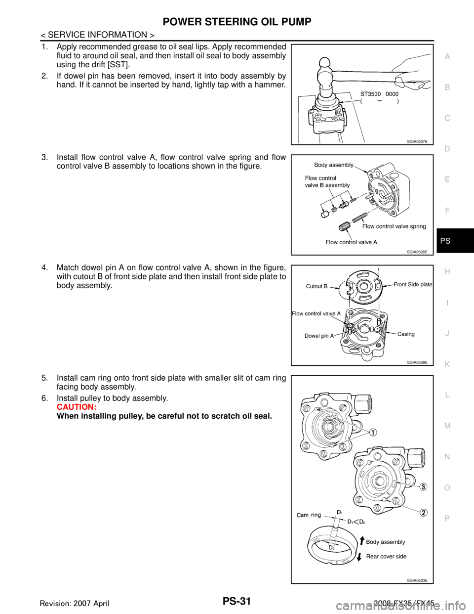
1. Apply recommended grease to oil seal lips. Apply recommended fluid to around oil seal, and then install oil seal to body assembly
using the drift [SST].
2. If dowel pin has been removed, insert it into body assembly by hand. If it cannot be inserted by hand, lightly tap with a hammer.
3. Install flow control valve A, flow control valve spring and flow control valve B assembly to locations shown in the figure.
4. Match dowel pin A on flow control valve A, shown in the figure, with cutout B of front side plate and then install front side plate to
body assembly.
5. Install cam ring onto front side pl ate with smaller slit of cam ring
facing body assembly.
6. Install pulley to body assembly. CAUTION:
When installing pulley, be car eful not to scratch oil seal.
SGIA0527E
SGIA0526E
SGIA0528E
SGIA0623E
3AA93ABC3ACD3AC03ACA3AC03AC63AC53A913A773A893A873A873A8E3A773A983AC73AC93AC03AC3
3A893A873A873A8F3A773A9D3AAF3A8A3A8C3A863A9D3AAF3A8B3A8C
Page 3488 of 3924
POWER STEERING OIL PUMPPS-33
< SERVICE INFORMATION >
C
DE
F
H I
J
K L
M A
B
PS
N
O P
INSPECTION BEFORE DISASSEMBLY
Disassemble power steering oil pump onl y if the following items are found.
Oil leakage from oil pump.
Deformed or damaged pulley
Poor performance
DISASSEMBLY
NOTE:
Fix oil pump in vise as the occasion demands.
CAUTION:
When retaining drive shaft in a vise, always use copper or alumi num plates between vise and shaft.
1. Unscrew three bracket bolts and remove bracket from rear cover.
2. Unscrew four rear cover bolts and remove rear cover from body assembly.
3. Remove gasket from body assembly.
4. Remove lock pin, cartridge and side plate from body assembly.
5. Remove pulley from drive shaft assembly.
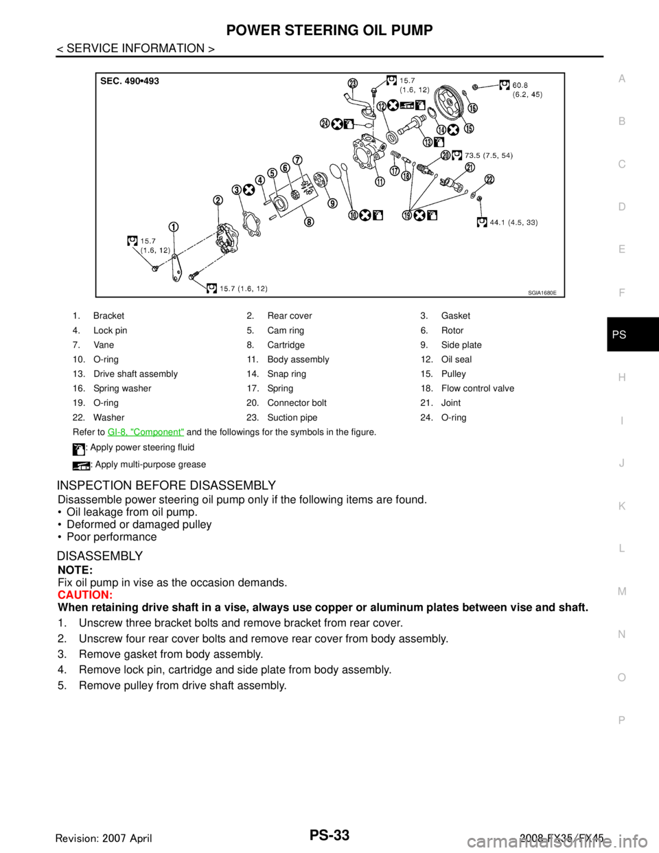
1. Bracket 2. Rear cover 3. Gasket
4. Lock pin 5. Cam ring 6. Rotor
7. Vane 8. Cartridge 9. Side plate
10. O-ring 11. Body assembly 12. Oil seal
13. Drive shaft assembly 14. Snap ring 15. Pulley
16. Spring washer 17. Spring 18. Flow control valve
19. O-ring 20. Connector bolt 21. Joint
22. Washer 23. Suction pipe 24. O-ring
Refer to GI-8, "
Component" and the followings for the symbols in the figure.
: Apply power steering fluid
: Apply multi-purpose grease
SGIA1680E
3AA93ABC3ACD3AC03ACA3AC03AC63AC53A913A773A893A873A873A8E3A773A983AC73AC93AC03AC3
3A893A873A873A8F3A773A9D3AAF3A8A3A8C3A863A9D3AAF3A8B3A8C
Page 3489 of 3924
PS-34
< SERVICE INFORMATION >
POWER STEERING OIL PUMP
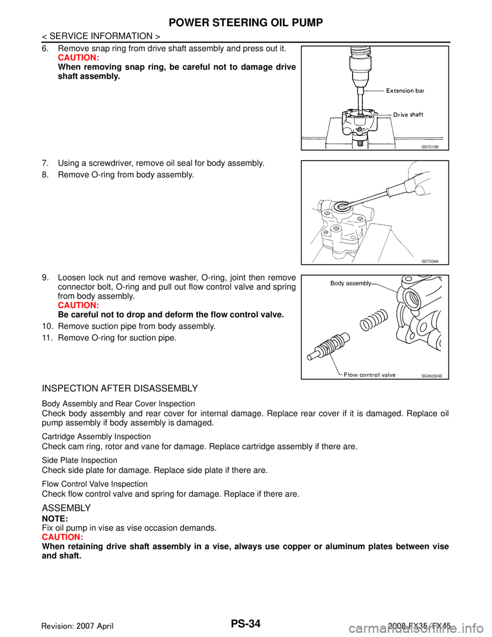
6. Remove snap ring from drive shaft assembly and press out it.CAUTION:
When removing snap ring, be careful not to damage drive
shaft assembly.
7. Using a screwdriver, remove oil seal for body assembly.
8. Remove O-ring from body assembly.
9. Loosen lock nut and remove washer, O-ring, joint then remove connector bolt, O-ring and pull out flow control valve and spring
from body assembly.
CAUTION:
Be careful not to drop and deform the flow control valve.
10. Remove suction pipe from body assembly.
11. Remove O-ring for suction pipe.
INSPECTION AFTER DISASSEMBLY
Body Assembly and Rear Cover Inspection
Check body assembly and rear cover for internal damage. Replace rear cover if it is damaged. Replace oil
pump assembly if body assembly is damaged.
Cartridge Assembly Inspection
Check cam ring, rotor and vane for damage. R eplace cartridge assembly if there are.
Side Plate Inspection
Check side plate for damage. Replace side plate if there are.
Flow Control Valve Inspection
Check flow control valve and spring for damage. Replace if there are.
ASSEMBLY
NOTE:
Fix oil pump in vise as vise occasion demands.
CAUTION:
When retaining drive shaft assembly in a vise, al ways use copper or aluminum plates between vise
and shaft.
SST010B
SST034A
SGIA0524E
3AA93ABC3ACD3AC03ACA3AC03AC63AC53A913A773A893A873A873A8E3A773A983AC73AC93AC03AC3
3A893A873A873A8F3A773A9D3AAF3A8A3A8C3A863A9D3AAF3A8B3A8C
Page 3490 of 3924
POWER STEERING OIL PUMPPS-35
< SERVICE INFORMATION >
C
DE
F
H I
J
K L
M A
B
PS
N
O P
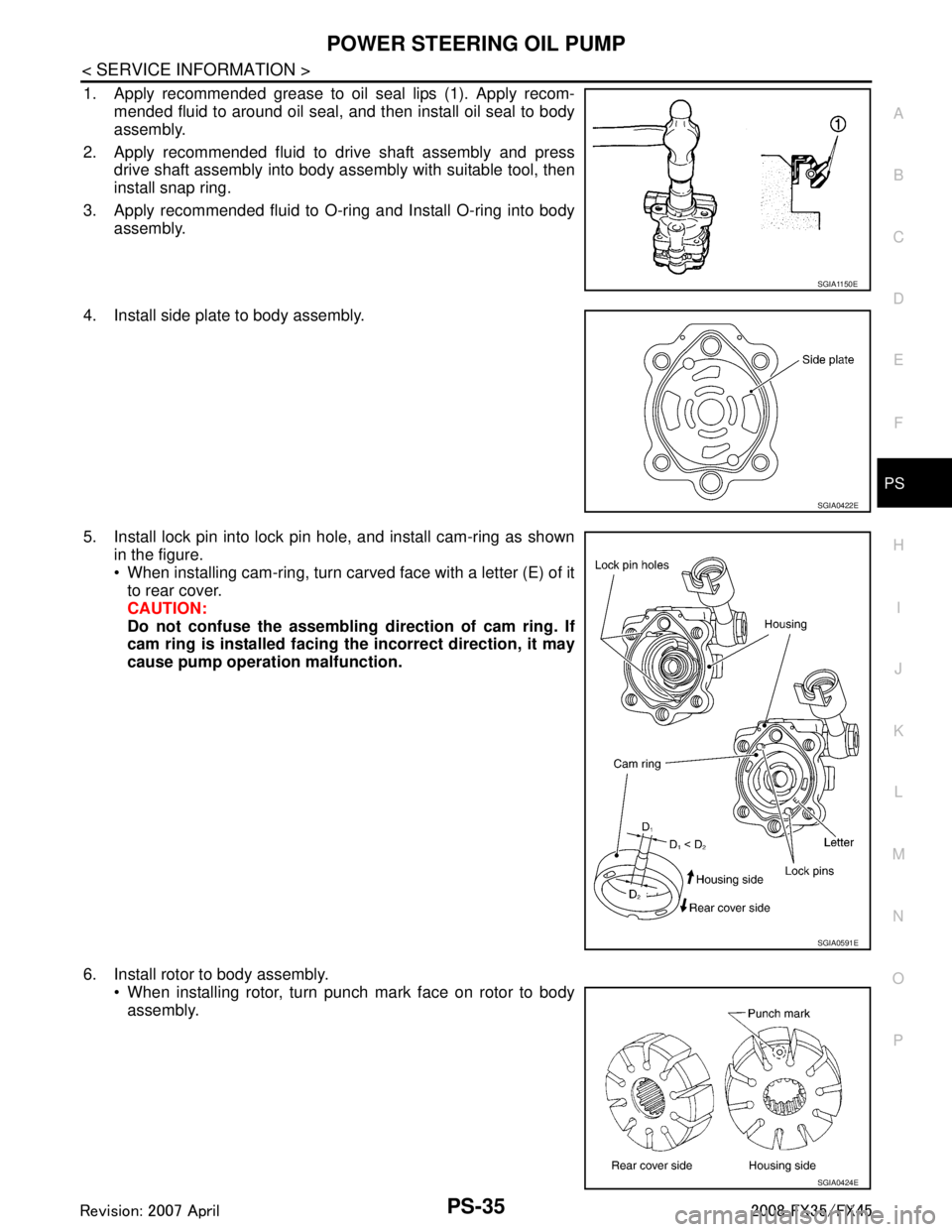
1. Apply recommended grease to oil seal lips (1). Apply recom- mended fluid to around oil seal, and then install oil seal to body
assembly.
2. Apply recommended fluid to drive shaft assembly and press drive shaft assembly into body assembly with suitable tool, then
install snap ring.
3. Apply recommended fluid to O-ring and Install O-ring into body assembly.
4. Install side plate to body assembly.
5. Install lock pin into lock pin hole, and install cam-ring as shown in the figure.
When installing cam-ring, turn carved face with a letter (E) of itto rear cover.
CAUTION:
Do not confuse the assembling direction of cam ring. If
cam ring is installed facing th e incorrect direction, it may
cause pump operation malfunction.
6. Install rotor to body assembly. When installing rotor, turn punch mark face on rotor to bodyassembly.
SGIA1150E
SGIA0422E
SGIA0591E
SGIA0424E
3AA93ABC3ACD3AC03ACA3AC03AC63AC53A913A773A893A873A873A8E3A773A983AC73AC93AC03AC3
3A893A873A873A8F3A773A9D3AAF3A8A3A8C3A863A9D3AAF3A8B3A8C
Page 3522 of 3924
SQUEAK AND RATTLE TROUBLE DIAGNOSESRF-7
< SERVICE INFORMATION >
C
DE
F
G H
J
K L
M A
B
RF
N
O P
Most of these incidents can be repaired by adjusting, se curing or insulating the item(s) or component(s) caus-
ing the noise.
SUNROOF/HEADLINING
Noises in the sunroof/headlining area can often be traced to one of the following:
1. Sunroof lid, rail, linkage or seals making a rattle or light knocking noise
2. Sunvisor shaft shaking in the holder
3. Front or rear windshield touching headlining and squeaking
Again, pressing on the components to stop the noise while duplicating the conditions can isolate most of these
incidents. Repairs usually consist of insulating with felt cloth tape.
SEATS
When isolating seat noise it's important to note the pos ition the seat is in and the load placed on the seat when
the noise is present. These conditions should be duplic ated when verifying and isolating the cause of the
noise.
Cause of seat noise include:
1. Headrest rods and holder
2. A squeak between the seat pad cushion and frame
3. Rear seatback lock and bracket
These noises can be isolated by moving or pressing on the suspected components while duplicating the con-
ditions under which the noise occurs. Most of thes e incidents can be repaired by repositioning the component
or applying urethane tape to the contact area.
UNDERHOOD
Some interior noise may be caused by components under the hood or on the engine wall. The noise is then
transmitted into the passenger compartment.
Causes of transmitted underhood noise include:
1. Any component mounted to the engine wall
2. Components that pass through the engine wall
3. Engine wall mounts and connectors
4. Loose radiator mounting pins
5. Hood bumpers out of adjustment
6. Hood striker out of adjustment
These noises can be difficult to isolate since they cannot be reached from the interior of the vehicle. The best
method is to secure, move or insulate one component at a time and test drive the vehicle. Also, engine RPM
or load can be changed to isolate the noise. Repairs c an usually be made by moving, adjusting, securing, or
insulating the component causing the noise.
3AA93ABC3ACD3AC03ACA3AC03AC63AC53A913A773A893A873A873A8E3A773A983AC73AC93AC03AC3
3A893A873A873A8F3A773A9D3AAF3A8A3A8C3A863A9D3AAF3A8B3A8C
Page 3543 of 3924
RFD-1
DRIVELINE/AXLE
CEF
G H
I
J
K L
M
SECTION RFD
A
B
RFD
N
O P
CONTENTS
REAR FINAL DRIVE
SERVICE INFORMATION .. ..........................2
PRECAUTIONS .............................................. .....2
Service Notice or Precaution ............................... ......2
PREPARATION ...................................................3
Special Service Tool ........................................... ......3
Commercial Service Tool ..........................................6
NOISE, VIBRATION AND HARSHNESS
(NVH) TROUBLESHOOTING .............................
7
NVH Troubleshooting Chart ................................ ......7
DESCRIPTION ....................................................8
Cross-Sectional View .......................................... ......8
DIFFERENTIAL GEAR OIL .................................9
Changing Differential Gear Oil ............................. .....9
Checking Differential Gear Oil ..................................9
FRONT OIL SEAL .............................................10
Removal and Installation .........................................10
SIDE OIL SEAL .................................................14
Removal and Installation .........................................14
REAR FINAL DRIVE ASSEMBLY ....................16
Removal and Installation .........................................16
Disassembly and Assembly .....................................17
SERVICE DATA AND SPECIFICATIONS
(SDS) .................................................................
38
General Specification ..............................................38
Inspection and Adjustment ......................................38
3AA93ABC3ACD3AC03ACA3AC03AC63AC53A913A773A893A873A873A8E3A773A983AC73AC93AC03AC3
3A893A873A873A8F3A773A9D3AAF3A8A3A8C3A863A9D3AAF3A8B3A8C
Page 3544 of 3924
RFD-2
< SERVICE INFORMATION >
PRECAUTIONS
SERVICE INFORMATION
PRECAUTIONS
Service Notice or PrecautionINFOID:0000000001327490
• Check for the correct installation status prior to removal or disassembly. If matching marks are required, becertain they do not interfere with the function of the parts when applied.
Overhaul should be done in a clean work area, it is preferable to work in dustproof area.
Before disassembly, using steam or white gasoline, completely remove sand and mud from the exterior of
the unit, preventing them from entering into the unit during disassembly or assembly.
Check appearance of the disassembled parts for dam age, deformation, and unusual wear. Replace them
with a new ones if necessary.
Gaskets, seals and O-rings should be replaced any time when the unit is disassembled.
In principle, tighten bolts or nuts gradually in several steps working diagonally from inside to outside. If tight-
ening sequence is specified, observe it.
Clean and flush the parts sufficiently and blow-dry them.
Be careful not to damage sliding surfaces and mating surfaces.
When applying sealant, remove the old sealant from t he mounting surface; then remove any moisture, oil,
and foreign materials from the application and mounting surfaces.
Always use shop paper for cleaning the inside of components.
Avoid using cotton gloves or shop rags to prevent entering of lint.
During assembly, observe the specified tightening tor que, and apply new gear oil, petroleum jelly, or multi-
purpose grease as specified for each vehicle, if necessary.
3AA93ABC3ACD3AC03ACA3AC03AC63AC53A913A773A893A873A873A8E3A773A983AC73AC93AC03AC3
3A893A873A873A8F3A773A9D3AAF3A8A3A8C3A863A9D3AAF3A8B3A8C