2008 INFINITI FX35 bearing
[x] Cancel search: bearingPage 2830 of 3924
SERVICE DATA AND SPECIFICATIONS (SDS)
FFD-39
< SERVICE INFORMATION >
C EF
G H
I
J
K L
M A
B
FFD
N
O P
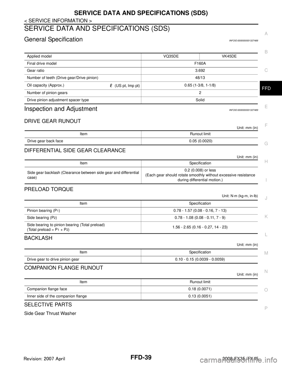
SERVICE DATA AND SPECIFICATIONS (SDS)
General SpecificationINFOID:0000000001327488
Inspection and AdjustmentINFOID:0000000001327489
DRIVE GEAR RUNOUT
Unit: mm (in)
DIFFERENTIAL SIDE GEAR CLEARANCE
Unit: mm (in)
PRELOAD TORQUE
Unit: N·m (kg-m, in-lb)
BACKLASH
Unit: mm (in)
COMPANION FLANGE RUNOUT
Unit: mm (in)
SELECTIVE PARTS
Side Gear Thrust Washer
Applied model VQ35DE VK45DE
Final drive model F160A
Gear ratio 3.692
Number of teeth (Drive gear/Drive pinion) 48/13
Oil capacity (Approx.) (US pt, lmp pt)0.65 (1-3/8, 1-1/8)
Number of pinion gears 2
Drive pinion adjustment spacer type Solid
Item Runout limit
Drive gear back face 0.05 (0.0020)
Item Specification
Side gear backlash (Clearance between side gear and differential
case) 0.2 (0.008) or less
(Each gear should rotate smoothly without excessive resistance during differential motion.)
Item Specification
Pinion bearing (P
1) 0.78 - 1.57 (0.08 - 0.16, 7 - 13)
Side bearing (P
2) 0.78 - 1.08 (0.08 - 0.11, 7 - 9)
Side bearing to pinion bearing (Total preload)
(Total preload = P
1 + P2) 1.56 - 2.65 (0.16 - 0.27, 14 - 23)
Item Specification
Drive gear to drive pinion gear 0.10 - 0.15 (0.0039 - 0.0059)
Item Runout limit
Companion flange face 0.18 (0.0071)
Inner side of the companion flange 0.13 (0.0051)
3AA93ABC3ACD3AC03ACA3AC03AC63AC53A913A773A893A873A873A8E3A773A983AC73AC93AC03AC3
3A893A873A873A8F3A773A9D3AAF3A8A3A8C3A863A9D3AAF3A8B3A8C
Page 2831 of 3924

FFD-40
< SERVICE INFORMATION >
SERVICE DATA AND SPECIFICATIONS (SDS)
Unit: mm (in)
*: Always check with the Parts Department for the latest parts information.
Pinion Height Adjusting Washer
Unit: mm (in)
*: Always check with the Parts Department for the latest parts information.
Drive Pinion Bearing Adjusting Washer
Unit: mm (in)
*: Always check with the Parts Department for the latest parts information.
Drive Pinion Adjusting Washer
Unit: mm (in)
*: Always check with the Parts Department for the latest parts information.
Side Bearing Adjusting Shim
Unit: mm (in)
*: Always check with the Parts Department for the latest parts information.
Side Bearing Adjusting Washer
Thickness Part number* Thickness Part number*
0.68 (0.0268)
0.71 (0.0280)
0.74 (0.0291)
0.77 (0.0303)
0.80 (0.0315)
0.83 (0.0327) 38424 W1010
38424 W1011
38424 W1012
38424 W1013
38424 W1014
38424 W1015 0.86 (0.0339)
0.89 (0.0350)
0.92 (0.0362)
0.95 (0.0374)
0.98 (0.0386)
1.01 (0.0398)38424 W1016
38424 W1017
38424 W1018
38424 W1019
38424 W1020
38424 W1021
Thickness Part number* Thickness Part number*
3.09 (0.1217)
3.12 (0.1228)
3.15 (0.1240)
3.18 (0.1252)
3.21 (0.1264)
3.24 (0.1276)
3.27 (0.1287)
3.30 (0.1299) 3.33 (0.1311)
3.36 (0.1323) 38154 U1500
38154 U1501
38154 U1502
38154 U1503
38154 U1504
38154 U1505
38154 U1506
38154 U1507
38154 U1508
38154 U1509 3.39 (0.1335)
3.42 (0.1346)
3.45 (0.1358)
3.48 (0.1370)
3.51 (0.1382)
3.54 (0.1394)
3.57 (0.1406)
3.60 (0.1417)
3.63 (0.1429)
3.66 (0.1441)38154 U1510
38154 U1511 38154U1512
38154 U1513
38154 U1514
38154 U1515
38154 U1516
38154 U1517
38154 U1518
38154 U1519
Thickness Part number* Thickness Part number*
3.81 (0.1500)
3.83 (0.1508)
3.85 (0.1516)
3.87 (0.1524)
3.89 (0.1531)
3.91 (0.1539)
3.93 (0.1547)
3.95 (0.1555) 38125 61001
38126 61001
38127 61001
38128 61001
39129 61001
38130 61001
38131 61001
38132 610013.97 (0.1563)
3.99 (0.1571)
4.01 (0.1579)
4.03 (0.1587)
4.05 (0.1594)
4.07 (0.1602)
4.09 (0.1610)
38133 61001
38134 61001
38135 61001
38136 61001
38137 61001
38138 61001
38139 61001
Thickness Part number* Thickness Part number*
5.19 (0.2043)
5.49 (0.2161)
5.79 (0.2280) 38151 AR000
38151 AR001
38151 AR002 6.09 (0.2398)
6.39 (0.2516)
38151 AR003
38151 AR004
Thickness Part number* Thickness Part number*
0.20 (0.0079)
0.25 (0.0098) 0.30 (0.0118) 38453 AR000
38453 AR001
38453 AR002 0.40 (0.0157)
0.50 (0.0197)
38453 AR003
38453 AR004
3AA93ABC3ACD3AC03ACA3AC03AC63AC53A913A773A893A873A873A8E3A773A983AC73AC93AC03AC3
3A893A873A873A8F3A773A9D3AAF3A8A3A8C3A863A9D3AAF3A8B3A8C
Page 2849 of 3924

FRONT SUSPENSION ASSEMBLYFSU-5
< SERVICE INFORMATION >
C
DF
G H
I
J
K L
M A
B
FSU
N
O P
FRONT SUSPENSION ASSEMBLY
On-Vehicle Inspection and ServiceINFOID:0000000001327537
Make sure the mounting conditions (looseness, back lash) of each component and component conditions
(wear, damage) are normal.
INSPECTION LOWER BALL JOINT END PLAY
1. Set front wheels in a straight-ahead position. Do not depress brake pedal.
2. Place an iron bar or similar tool bet ween transverse link and steering knuckle.
3. Measure axial end play by prying it up and down.
CAUTION:
Be careful not to damage ball joint boot.
STRUT INSPECTION
Check strut for oil leakage, damage and replace if there are. Refer to FSU-10.
Wheel Alignment InspectionINFOID:0000000001327538
DESCRIPTION
Measure wheel alignment under unladen conditions.
NOTE:
Unladen conditions mean that fuel, engine coolant, and l ubricant are full. Spare tire, jack, hand tools and
mats are designated positions.
PRELIMINARY CHECK
Check tires for improper air pressure and wear.
Check road wheels for runout.
Check wheel bearing axial end play.
Check ball joint axial end play of compression rod, upper link, and steering knuckle
Check shock absorber operation.
Check each mounting part of axle and suspension for looseness and deformation.
Check each link, rod and member for cracks, deformation and other damage.
Check vehicle posture.
GENERAL INFORMATION AND RECOMMENDATIONS
A four-wheel thrust alignment should be performed.
- This type of alignment is recomm ended for any NISSAN/INFINITI vehicle.
- The four-wheel “thrust” process helps ensure that t he vehicle is properly aligned and the steering wheel is
centered.
- The alignment rack itself should be capable of accepting any NISSAN/INFINITI vehicle.
- The rack should be checked to ensure that it is level.
Make sure the machine is properly calibrated.
- Your alignment equipment should be regularly ca librated in order to give correct information.
- Check with the manufacturer of your specific equi pment for their recommended Service/Calibration Sched-
ule.
THE ALIGNMENT PROCESS
IMPORTANT:
Use only the alignment specificati ons listed in this Service Manual.
When displaying the alignment settings, many alignment machines use “indicators”: (Green/red, plus or
minus, Go/No Go). Do NOT use these indicators.
- The alignment specifications programmed into your machine that operate these indicators may not be cor-
rect.
- This may result in an ERROR.
Some newer alignment machines are equipped with an optional “Rolling Compensation” method to “com-
pensate” the sensors (alignment targets or head units). DO NOT use this “Rolling Compensation”
method. Axial end play : 0 mm (0 in)
3AA93ABC3ACD3AC03ACA3AC03AC63AC53A913A773A893A873A873A8E3A773A983AC73AC93AC03AC3
3A893A873A873A8F3A773A9D3AAF3A8A3A8C3A863A9D3AAF3A8B3A8C
Page 2851 of 3924
FRONT SUSPENSION ASSEMBLYFSU-7
< SERVICE INFORMATION >
C
DF
G H
I
J
K L
M A
B
FSU
N
O P
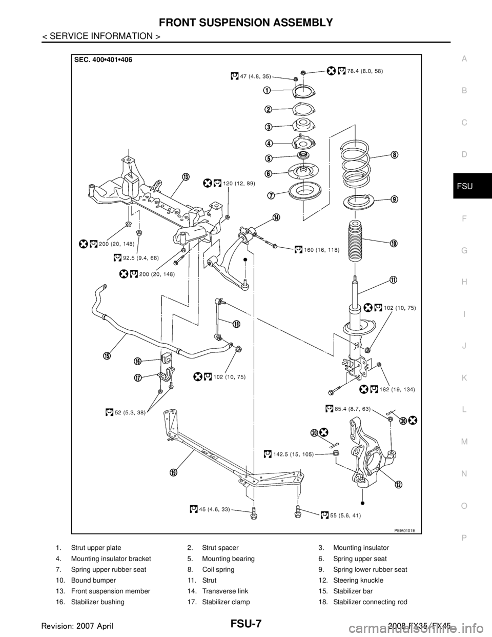
1. Strut upper plate 2. Strut spacer 3. Mounting insulator
4. Mounting insulator bracket 5. Mounting bearing 6. Spring upper seat
7. Spring upper rubber seat 8. Coil spring 9. Spring lower rubber seat
10. Bound bumper 11. Strut 12. Steering knuckle
13. Front suspension member 14. Transverse link 15. Stabilizer bar
16. Stabilizer bushing 17. Stabilizer clamp 18. Stabilizer connecting rod
PEIA0101E
3AA93ABC3ACD3AC03ACA3AC03AC63AC53A913A773A893A873A873A8E3A773A983AC73AC93AC03AC3
3A893A873A873A8F3A773A9D3AAF3A8A3A8C3A863A9D3AAF3A8B3A8C
Page 2855 of 3924
COIL SPRING AND STRUTFSU-11
< SERVICE INFORMATION >
C
DF
G H
I
J
K L
M A
B
FSU
N
O P
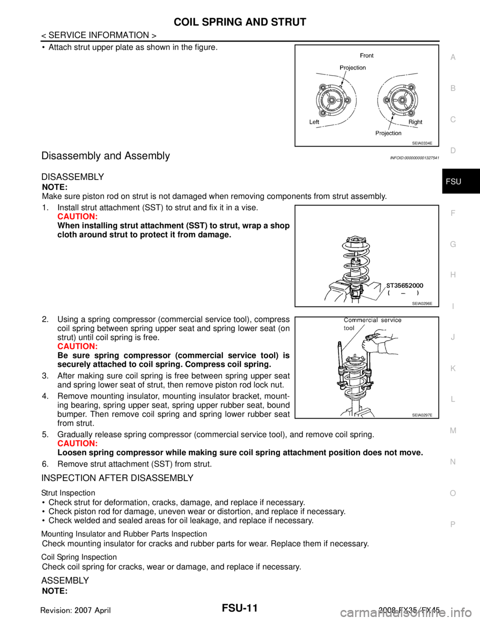
Attach strut upper plate as shown in the figure.
Disassembly and AssemblyINFOID:0000000001327541
DISASSEMBLY
NOTE:
Make sure piston rod on strut is not damaged when removing components from strut assembly.
1. Install strut attachment (SST) to strut and fix it in a vise. CAUTION:
When installing strut attachment (SST) to strut, wrap a shop
cloth around strut to protect it from damage.
2. Using a spring compressor (commercial service tool), compress coil spring between spring upper seat and spring lower seat (on
strut) until coil spring is free.
CAUTION:
Be sure spring compressor (commercial service tool) is
securely attached to coil sp ring. Compress coil spring.
3. After making sure coil spring is free between spring upper seat and spring lower seat of strut, then remove piston rod lock nut.
4. Remove mounting insulator, mounting insulator bracket, mount- ing bearing, spring upper seat, spring upper rubber seat, bound
bumper. Then remove coil spring and spring lower rubber seat
from strut.
5. Gradually release spring compressor (commercial service tool), and remove coil spring. CAUTION:
Loosen spring compressor whil e making sure coil spring attachment position does not move.
6. Remove strut attachment (SST) from strut.
INSPECTION AFTER DISASSEMBLY
Strut Inspection
Check strut for deformation, cracks, damage, and replace if necessary.
Check piston rod for damage, uneven wear or distortion, and replace if necessary.
Check welded and sealed areas for oil leakage, and replace if necessary.
Mounting Insulator and Rubber Parts Inspection
Check mounting insulator for cracks and rubber parts for wear. Replace them if necessary.
Coil Spring Inspection
Check coil spring for cracks, wear or damage, and replace if necessary.
ASSEMBLY
NOTE:
SEIA0334E
SEIA0296E
SEIA0297E
3AA93ABC3ACD3AC03ACA3AC03AC63AC53A913A773A893A873A873A8E3A773A983AC73AC93AC03AC3
3A893A873A873A8F3A773A9D3AAF3A8A3A8C3A863A9D3AAF3A8B3A8C
Page 2856 of 3924
FSU-12
< SERVICE INFORMATION >
COIL SPRING AND STRUT
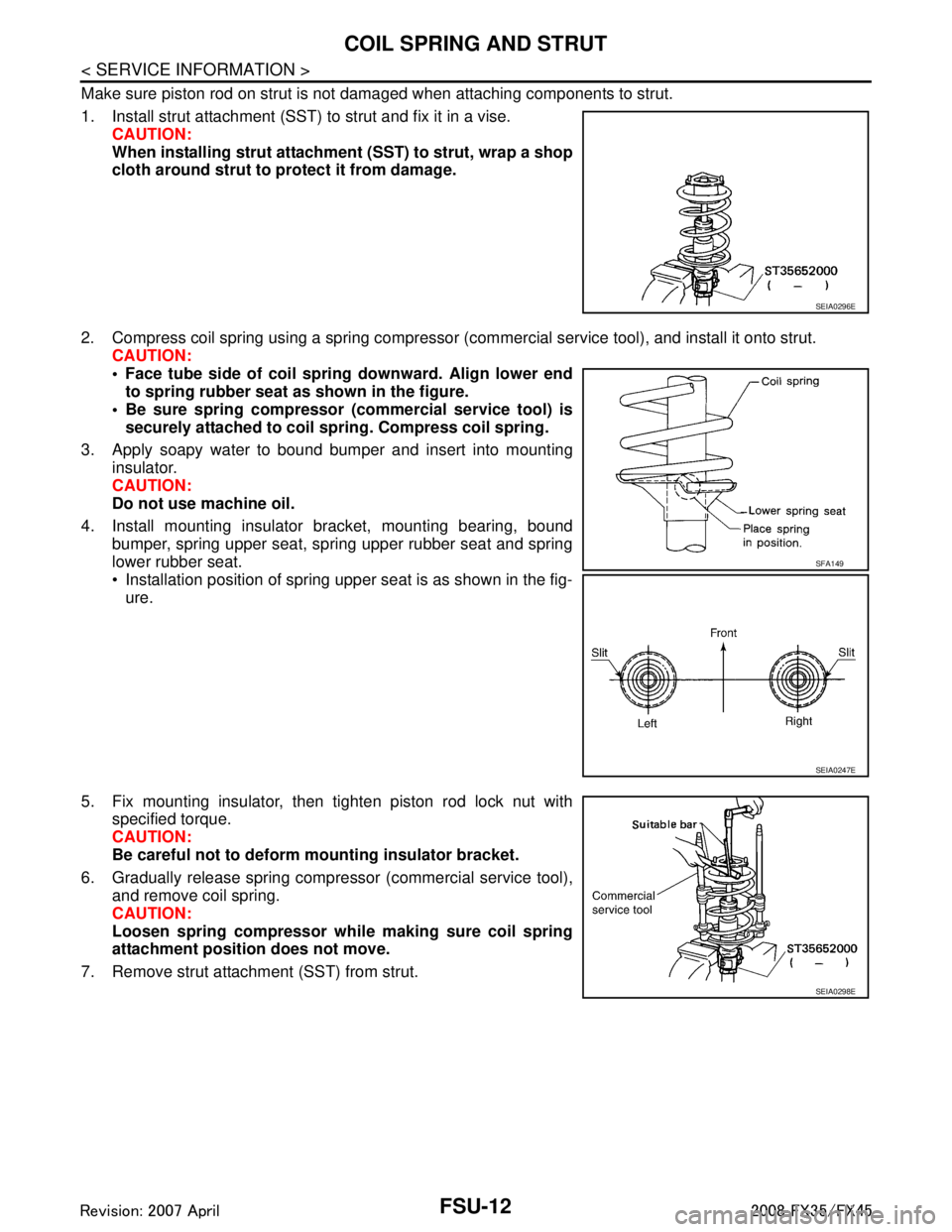
Make sure piston rod on strut is not damaged when attaching components to strut.
1. Install strut attachment (SST) to strut and fix it in a vise.CAUTION:
When installing strut attachment (SST) to strut, wrap a shop
cloth around strut to protect it from damage.
2. Compress coil spring using a spring compressor (c ommercial service tool), and install it onto strut.
CAUTION:
Face tube side of coil spri ng downward. Align lower end
to spring rubber seat as shown in the figure.
Be sure spring compressor (commercial service tool) is securely attached to coil sp ring. Compress coil spring.
3. Apply soapy water to bound bumper and insert into mounting insulator.
CAUTION:
Do not use machine oil.
4. Install mounting insulator bracket, mounting bearing, bound bumper, spring upper seat, spring upper rubber seat and spring
lower rubber seat.
Installation position of spring upper seat is as shown in the fig-ure.
5. Fix mounting insulator, then tighten piston rod lock nut with specified torque.
CAUTION:
Be careful not to deform mounting insulator bracket.
6. Gradually release spring compressor (commercial service tool), and remove coil spring.
CAUTION:
Loosen spring compressor whil e making sure coil spring
attachment position does not move.
7. Remove strut attachment (SST) from strut.
SEIA0296E
SFA149
SEIA0247E
SEIA0298E
3AA93ABC3ACD3AC03ACA3AC03AC63AC53A913A773A893A873A873A8E3A773A983AC73AC93AC03AC3
3A893A873A873A8F3A773A9D3AAF3A8A3A8C3A863A9D3AAF3A8B3A8C
Page 2866 of 3924
GI-4
< SERVICE INFORMATION >
PRECAUTIONS
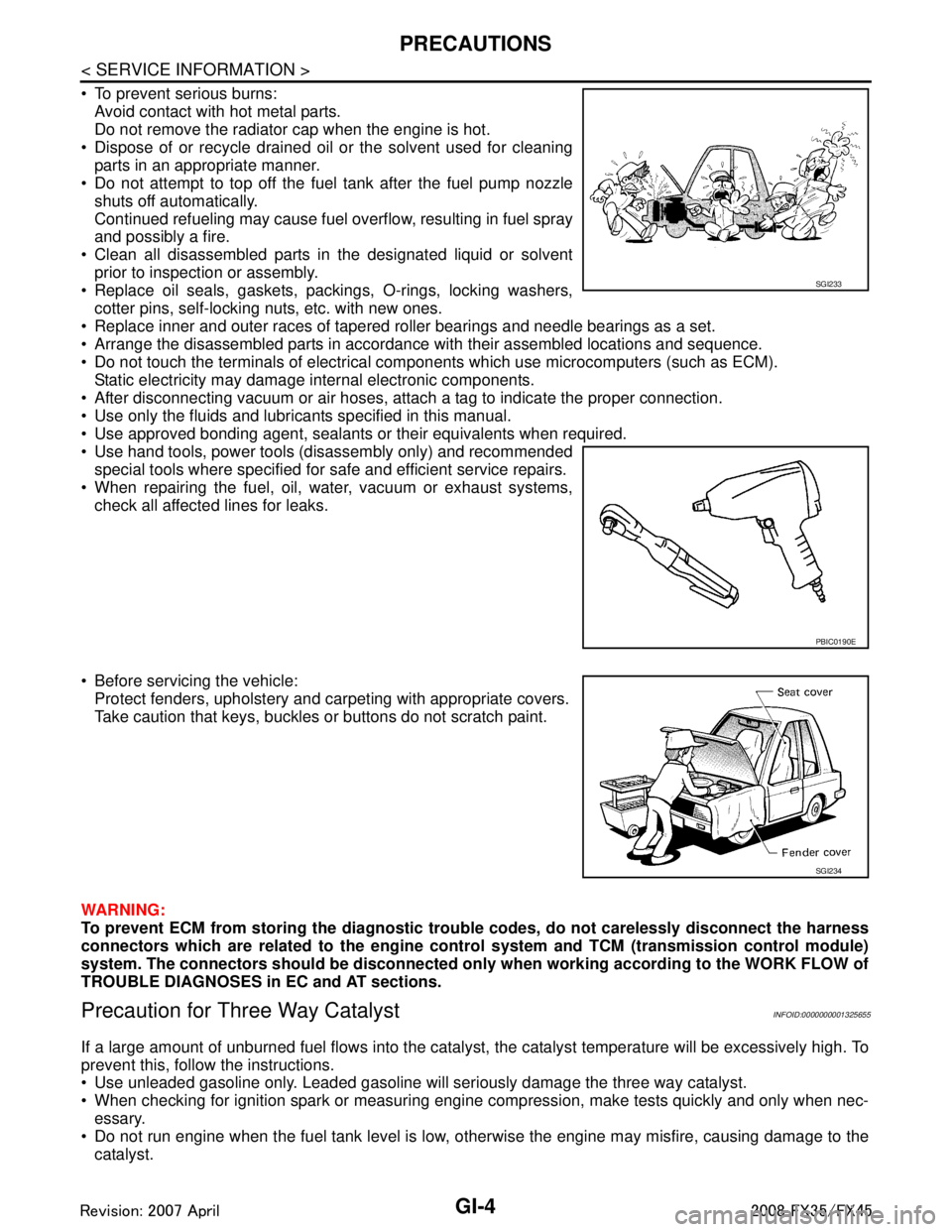
To prevent serious burns:Avoid contact with hot metal parts.
Do not remove the radiator cap when the engine is hot.
Dispose of or recycle drained oil or the solvent used for cleaning parts in an appropriate manner.
Do not attempt to top off the fuel tank after the fuel pump nozzle
shuts off automatically.
Continued refueling may cause fuel overflow, resulting in fuel spray
and possibly a fire.
Clean all disassembled parts in the designated liquid or solvent prior to inspection or assembly.
Replace oil seals, gaskets, packings, O-rings, locking washers, cotter pins, self-locking nuts, etc. with new ones.
Replace inner and outer races of tapered roller bearings and needle bearings as a set.
Arrange the disassembled parts in accordance with their assembled locations and sequence.
Do not touch the terminals of electrical com ponents which use microcomputers (such as ECM).
Static electricity may damage internal electronic components.
After disconnecting vacuum or air hoses, atta ch a tag to indicate the proper connection.
Use only the fluids and lubricants specified in this manual.
Use approved bonding agent, sealants or their equivalents when required.
Use hand tools, power tools (disassembly only) and recommended special tools where specified for safe and efficient service repairs.
When repairing the fuel, oil, water, vacuum or exhaust systems,
check all affected lines for leaks.
Before servicing the vehicle: Protect fenders, upholstery and carpeting with appropriate covers.
Take caution that keys, buckles or buttons do not scratch paint.
WARNING:
To prevent ECM from storing the diagnostic tro uble codes, do not carelessly disconnect the harness
connectors which are related to the engine cont rol system and TCM (transmission control module)
system. The connectors should be disconnected on ly when working according to the WORK FLOW of
TROUBLE DIAGNOSES in EC and AT sections.
Precaution for Three Way CatalystINFOID:0000000001325655
If a large amount of unburned fuel flows into the catalyst , the catalyst temperature will be excessively high. To
prevent this, follow the instructions.
Use unleaded gasoline only. Leaded gasoline will seriously damage the three way catalyst.
When checking for ignition spark or measuring engine compression, make tests quickly and only when nec- essary.
Do not run engine when the fuel tank level is low, otherwise the engine may misfire, causing damage to the
catalyst.
SGI233
PBIC0190E
SGI234
3AA93ABC3ACD3AC03ACA3AC03AC63AC53A913A773A893A873A873A8E3A773A983AC73AC93AC03AC3
3A893A873A873A8F3A773A9D3AAF3A8A3A8C3A863A9D3AAF3A8B3A8C
Page 3351 of 3924
MA-34
< SERVICE INFORMATION >
CHASSIS AND BODY MAINTENANCE
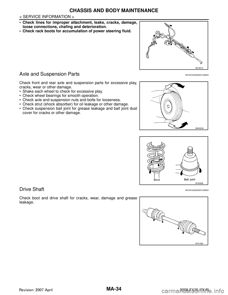
Check lines for improper attachment, leaks, cracks, damage,loose connections, chaf ing and deterioration.
Check rack boots for accumulati on of power steering fluid.
Axle and Suspension PartsINFOID:0000000001328934
Check front and rear axle and suspension parts for excessive play,
cracks, wear or other damage.
Shake each wheel to check for excessive play.
Check wheel bearings for smooth operation.
Check axle and suspension nuts and bolts for looseness.
Check strut (shock absorber) for oil leakage or other damage.
Check suspension ball joint for grease leakage and ball joint dust
cover for cracks or other damage.
Drive ShaftINFOID:0000000001328935
Check boot and drive shaft for cracks, wear, damage and grease
leakage.
SST851C
SMA525A
SFA392B
SFA108A
3AA93ABC3ACD3AC03ACA3AC03AC63AC53A913A773A893A873A873A8E3A773A983AC73AC93AC03AC3
3A893A873A873A8F3A773A9D3AAF3A8A3A8C3A863A9D3AAF3A8B3A8C