2008 INFINITI FX35 bearing
[x] Cancel search: bearingPage 3454 of 3924
PR-12
< SERVICE INFORMATION >
REAR PROPELLER SHAFT
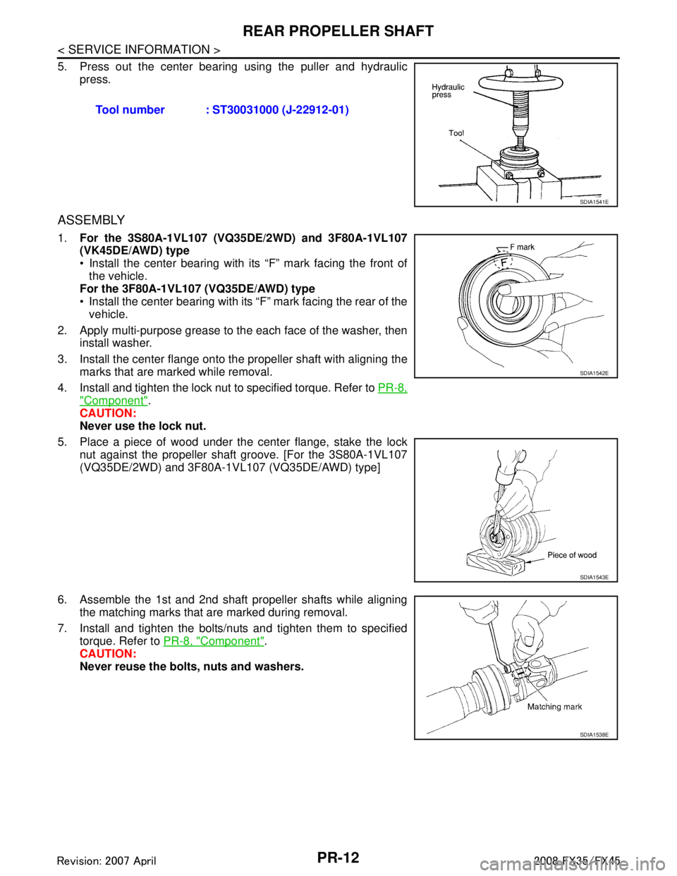
5. Press out the center bearing using the puller and hydraulic
press.
ASSEMBLY
1. For the 3S80A-1VL107 (VQ35DE/2WD) and 3F80A-1VL107
(VK45DE/AWD) type
Install the center bearing with its “F” mark facing the front of
the vehicle.
For the 3F80A-1VL107 (VQ35DE/AWD) type
Install the center bearing with its “F” mark facing the rear of the vehicle.
2. Apply multi-purpose grease to the each face of the washer, then install washer.
3. Install the center flange onto the propeller shaft with aligning the marks that are marked while removal.
4. Install and tighten the lock nut to specified torque. Refer to PR-8,
"Component".
CAUTION:
Never use the lock nut.
5. Place a piece of wood under the center flange, stake the lock nut against the propeller shaft groove. [For the 3S80A-1VL107
(VQ35DE/2WD) and 3F80A-1 VL107 (VQ35DE/AWD) type]
6. Assemble the 1st and 2nd shaft propeller shafts while aligning the matching marks that are marked during removal.
7. Install and tighten the bolts/nuts and tighten them to specified torque. Refer to PR-8, "
Component".
CAUTION:
Never reuse the bolts, nuts and washers. Tool number : ST30031000 (J-22912-01)
SDIA1541E
SDIA1542E
SDIA1543E
SDIA1538E
3AA93ABC3ACD3AC03ACA3AC03AC63AC53A913A773A893A873A873A8E3A773A983AC73AC93AC03AC3
3A893A873A873A8F3A773A9D3AAF3A8A3A8C3A863A9D3AAF3A8B3A8C
Page 3476 of 3924
POWER STEERING GEAR AND LINKAGEPS-21
< SERVICE INFORMATION >
C
DE
F
H I
J
K L
M A
B
PS
N
O P
When removing boots, be careful not to damage inner socket and gear housing assembly. If they
are damaged, change th em to avoid oil leaks.
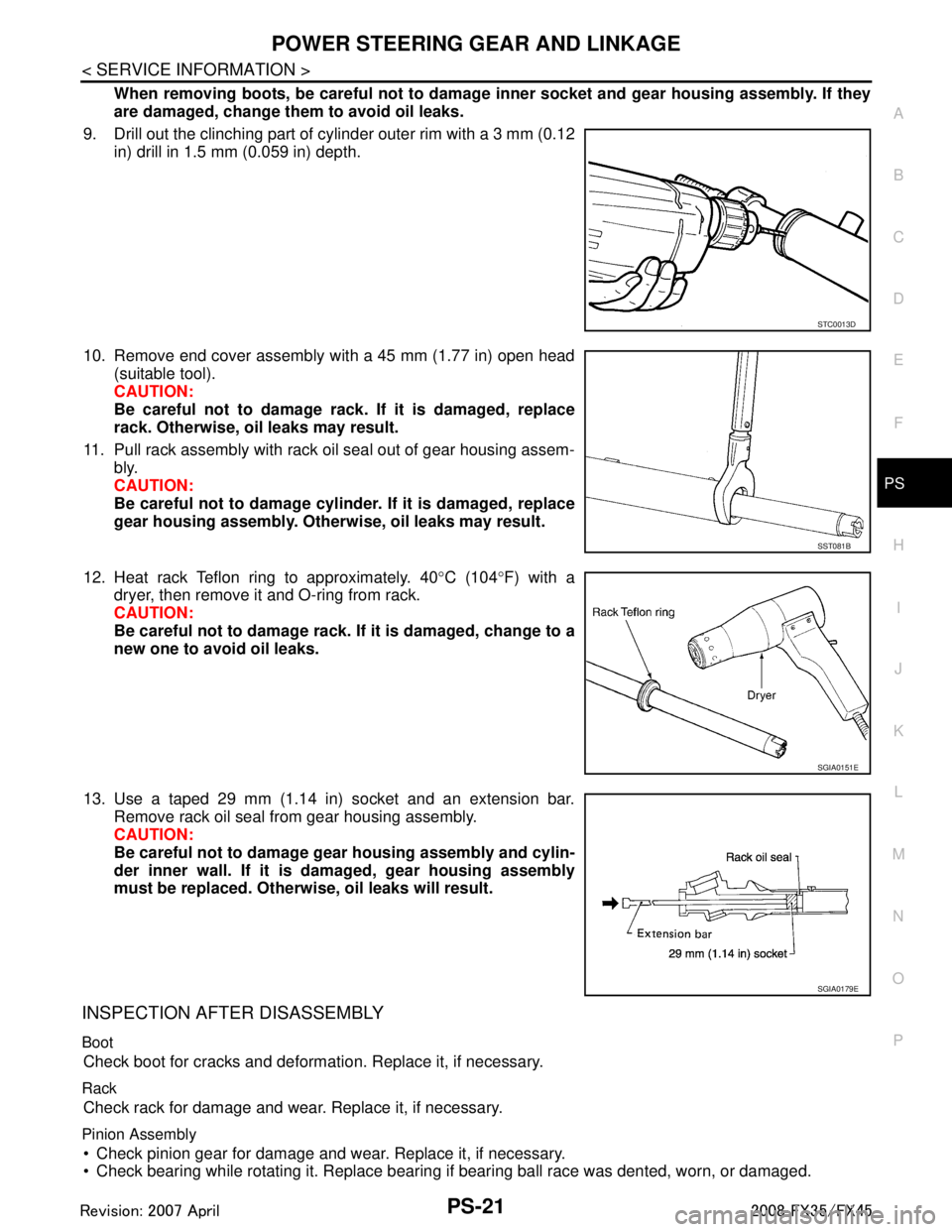
9. Drill out the clinching part of cylinder outer rim with a 3 mm (0.12 in) drill in 1.5 mm (0.059 in) depth.
10. Remove end cover assembly with a 45 mm (1.77 in) open head (suitable tool).
CAUTION:
Be careful not to damage rack. If it is damaged, replace
rack. Otherwise, oil leaks may result.
11. Pull rack assembly with rack oil seal out of gear housing assem- bly.
CAUTION:
Be careful not to damage cylinder. If it is damaged, replace
gear housing assembly. Otherw ise, oil leaks may result.
12. Heat rack Teflon ring to approximately. 40 °C (104 °F) with a
dryer, then remove it and O-ring from rack.
CAUTION:
Be careful not to damage rack. If it is damaged, change to a
new one to avoid oil leaks.
13. Use a taped 29 mm (1.14 in) socket and an extension bar. Remove rack oil seal from gear housing assembly.
CAUTION:
Be careful not to damage gear housing assembly and cylin-
der inner wall. If it is damaged, gear housing assembly
must be replaced. Otherwi se, oil leaks will result.
INSPECTION AFTER DISASSEMBLY
Boot
Check boot for cracks and deformati on. Replace it, if necessary.
Rack
Check rack for damage and wear. Replace it, if necessary.
Pinion Assembly
Check pinion gear for damage and wear. Replace it, if necessary.
Check bearing while rotating it. Replace bearing if bearing ball race was dented, worn, or damaged.
STC0013D
SST081B
SGIA0151E
SGIA0179E
3AA93ABC3ACD3AC03ACA3AC03AC63AC53A913A773A893A873A873A8E3A773A983AC73AC93AC03AC3
3A893A873A873A8F3A773A9D3AAF3A8A3A8C3A863A9D3AAF3A8B3A8C
Page 3499 of 3924
RAX-1
DRIVELINE/AXLE
CEF
G H
I
J
K L
M
SECTION RAX
A
B
RAX
N
O P
CONTENTS
REAR AXLE
SERVICE INFORMATION .. ..........................2
PRECAUTIONS .............................................. .....2
Caution ................................................................ ......2
PREPARATION ...................................................3
Special Service Tool ........................................... ......3
Commercial Service Tool ..........................................4
NOISE, VIBRATION AND HARSHNESS
(NVH) TROUBLESHOOTING .............................
5
NVH Troubleshooting Chart ................................ ......5
REAR WHEEL HUB AND KNUCKLE ...............6
On-Vehicle Inspection ......................................... .....6
Removal and Installation ..........................................6
Disassembly and Assembly ......................................7
REAR DRIVE SHAFT ........................................10
Removal and Installation .........................................10
Disassembly and Assembly .....................................10
SERVICE DATA AND SPECIFICATIONS
(SDS) .................................................................
17
Wheel Bearing .........................................................17
Drive Shaft ...............................................................17
3AA93ABC3ACD3AC03ACA3AC03AC63AC53A913A773A893A873A873A8E3A773A983AC73AC93AC03AC3
3A893A873A873A8F3A773A9D3AAF3A8A3A8C3A863A9D3AAF3A8B3A8C
Page 3501 of 3924
PREPARATIONRAX-3
< SERVICE INFORMATION >
CEF
G H
I
J
K L
M A
B
RAX
N
O P
PREPARATION
Special Service ToolINFOID:0000000001327523
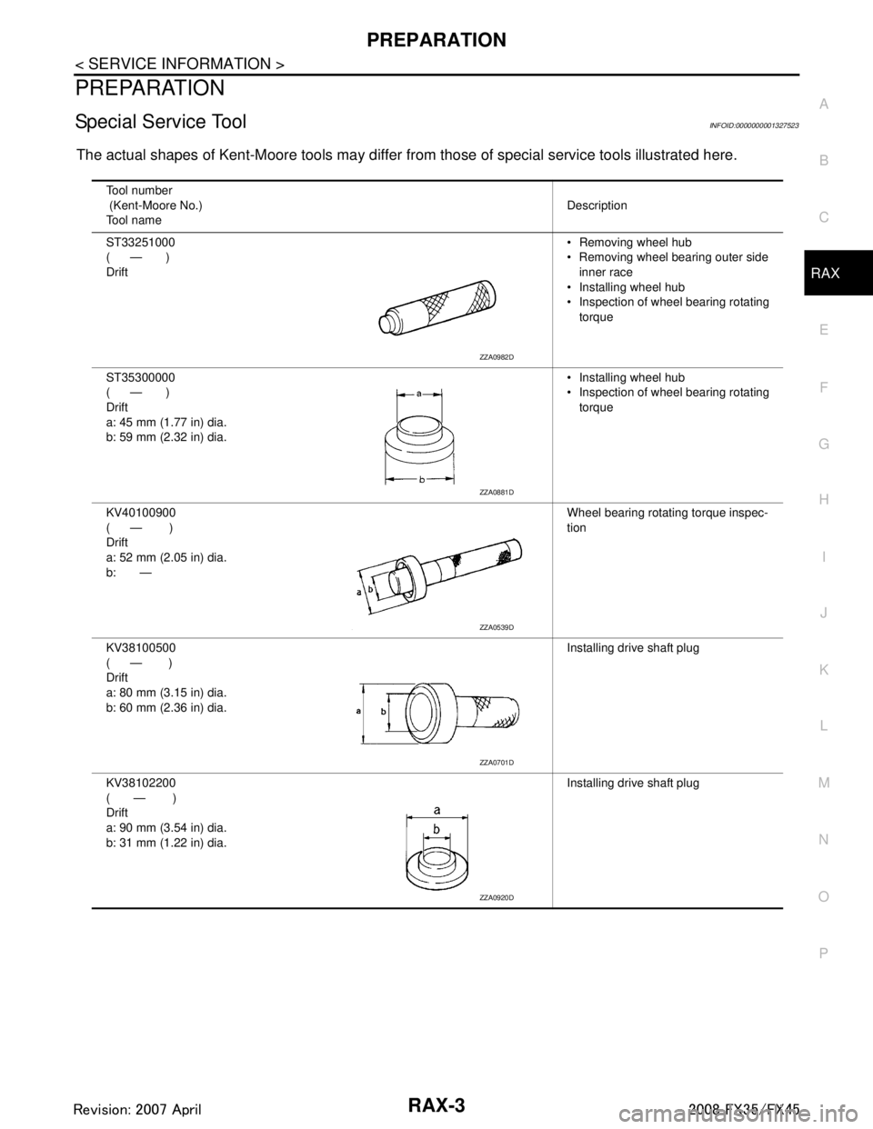
The actual shapes of Kent-Moore tools may differ fr om those of special service tools illustrated here.
Tool number
(Kent-Moore No.)
Tool name Description
ST33251000
( — )
Drift Removing wheel hub
Removing wheel bearing outer side
inner race
Installing wheel hub
Inspection of wheel bearing rotating torque
ST35300000
( — )
Drift
a: 45 mm (1.77 in) dia.
b: 59 mm (2.32 in) dia. Installing wheel hub
Inspection of wheel bearing rotating
torque
KV40100900
( — )
Drift
a: 52 mm (2.05 in) dia.
b: — Wheel bearing rotating torque inspec-
tion
KV38100500
( — )
Drift
a: 80 mm (3.15 in) dia.
b: 60 mm (2.36 in) dia. Installing drive shaft plug
KV38102200
( — )
Drift
a: 90 mm (3.54 in) dia.
b: 31 mm (1.22 in) dia. Installing drive shaft plug
ZZA0982D
ZZA0881D
ZZA0539D
ZZA0701D
ZZA0920D
3AA93ABC3ACD3AC03ACA3AC03AC63AC53A913A773A893A873A873A8E3A773A983AC73AC93AC03AC3
3A893A873A873A8F3A773A9D3AAF3A8A3A8C3A863A9D3AAF3A8B3A8C
Page 3504 of 3924
RAX-6
< SERVICE INFORMATION >
REAR WHEEL HUB AND KNUCKLE
REAR WHEEL HUB AND KNUCKLE
On-Vehicle InspectionINFOID:0000000001327526
Make sure the mounting conditions (looseness, back lash) of each component and component status (wear,
damage) are normal.
WHEEL BEARING INSPECTION
With the vehicle raised, inspect the following.
Move wheel hub in the axial direction by hand. Che ck that there is no looseness of front wheel bearing.
Rotate wheel hub and make sure there is no unusual noi se or other irregular conditions. If there are any
irregular conditions, replace wheel hub and bearing assembly.
Removal and InstallationINFOID:0000000001327527
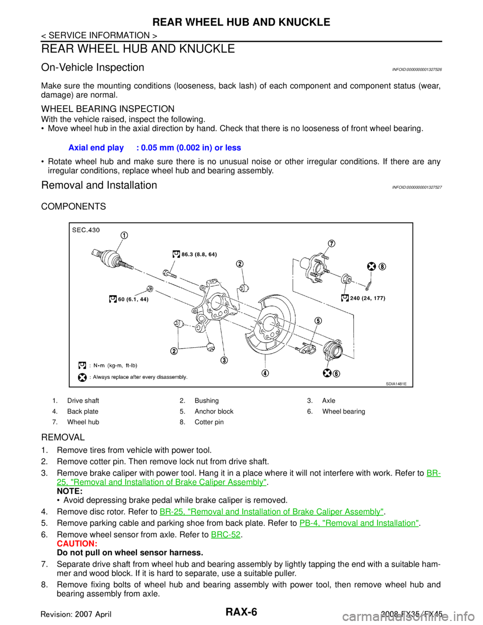
COMPONENTS
REMOVAL
1. Remove tires from vehicle with power tool.
2. Remove cotter pin. Then remove lock nut from drive shaft.
3. Remove brake caliper with power tool. Hang it in a place where it will not interfere with work. Refer to BR-
25, "Removal and Installation of Brake Caliper Assembly".
NOTE:
Avoid depressing brake pedal while brake caliper is removed.
4. Remove disc rotor. Refer to BR-25, "
Removal and Installation of Brake Caliper Assembly".
5. Remove parking cable and parking shoe from back plate. Refer to PB-4, "
Removal and Installation".
6. Remove wheel sensor from axle. Refer to BRC-52
.
CAUTION:
Do not pull on wheel sensor harness.
7. Separate drive shaft from wheel hub and bearing assembly by lightly tapping the end with a suitable ham- mer and wood block. If it is hard to separate, use a suitable puller.
8. Remove fixing bolts of wheel hub and bearing assembly with power tool, then remove wheel hub and bearing assembly from axle.Axial end play : 0.05 mm (0.002 in) or less
1. Drive shaft 2. Bushing 3. Axle
4. Back plate 5. Anchor block 6. Wheel bearing
7. Wheel hub 8. Cotter pin
SDIA1481E
3AA93ABC3ACD3AC03ACA3AC03AC63AC53A913A773A893A873A873A8E3A773A983AC73AC93AC03AC3
3A893A873A873A8F3A773A9D3AAF3A8A3A8C3A863A9D3AAF3A8B3A8C
Page 3505 of 3924
REAR WHEEL HUB AND KNUCKLERAX-7
< SERVICE INFORMATION >
CEF
G H
I
J
K L
M A
B
RAX
N
O P
9. Remove parking brake cable and parking brake shoe from back plate. Refer to PB-6 and PB-4.
10. Remove fixing nuts of anchor block with power tool , then remove anchor block and back plate from axle.
11. Loosen fixing bolts and nuts of front lower link, radius rod, and rear lower link in side of suspension mem-
ber.
12. Set jack under rear lower link. Then remove fixing bolt in front lower link side of shock absorber with power tool.
13. Remove bolt and nut in axle side of rear lower link with power tool. Then remove coil spring. Refer to RSU-15
.
14. Remove fixing bolts and nuts in axle side of fr ont lower link, radius rod with power tool.
15. Remove suspension arm and cotter pin at axle, then loosen mounting nut.
16. Use a ball joint remover (suitable tool) to remove suspension arm from axle. Be careful not to damage ball joint boot.
CAUTION:
Tighten temporarily mounting nu t to prevent damage to threads and to prevent ball joint remover
(suitable tool) from coming off.
17. Remove axle from vehicle.
INSPECTION AFTER REMOVAL
Check for deformity, cracks and damage on each parts, replace if necessary.
Ball Joint Inspection
Check for boot breakage, axial looseness, and tor que of suspension arm ball joint. Refer to RSU-11, "Removal
and Installation".
INSTALLATION
Refer to "Removal and Installation" for tightening torque. Install in the reverse order of removal.
NOTE:
Refer to component parts location and do not reuse non-reusable parts.
Perform final tightening of installation position of suspension links (rubber bushing) under unladen conditions
with tires on level ground, Check wheel alignment. Refer to RSU-5, "
Wheel AlignmentInspection".
After adjusting wheel alignment, adjust neutral position of steering angle sensor. Refer to BRC-8, "
Adjust-
ment of Steering Angle Sensor Neutral Position".
Disassembly and AssemblyINFOID:0000000001327528
DISASSEMBLY
Wheel Bearing
CAUTION:
Do not disassemble if wheel bearing has no trouble.
1. Remove wheel bearing fixing bolts and anchor block fixing nuts, and remove wheel hub and bearing assembly, back plate and anchor block from axle.
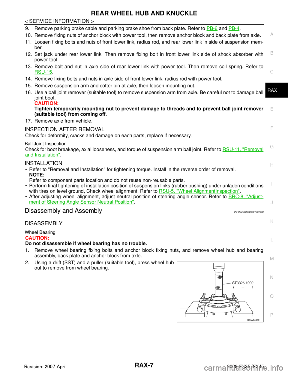
2. Using a drift (SST) and a puller (suitable tool), press wheel hub out to remove from wheel bearing.
SDIA1482E
3AA93ABC3ACD3AC03ACA3AC03AC63AC53A913A773A893A873A873A8E3A773A983AC73AC93AC03AC3
3A893A873A873A8F3A773A9D3AAF3A8A3A8C3A863A9D3AAF3A8B3A8C
Page 3506 of 3924
RAX-8
< SERVICE INFORMATION >
REAR WHEEL HUB AND KNUCKLE
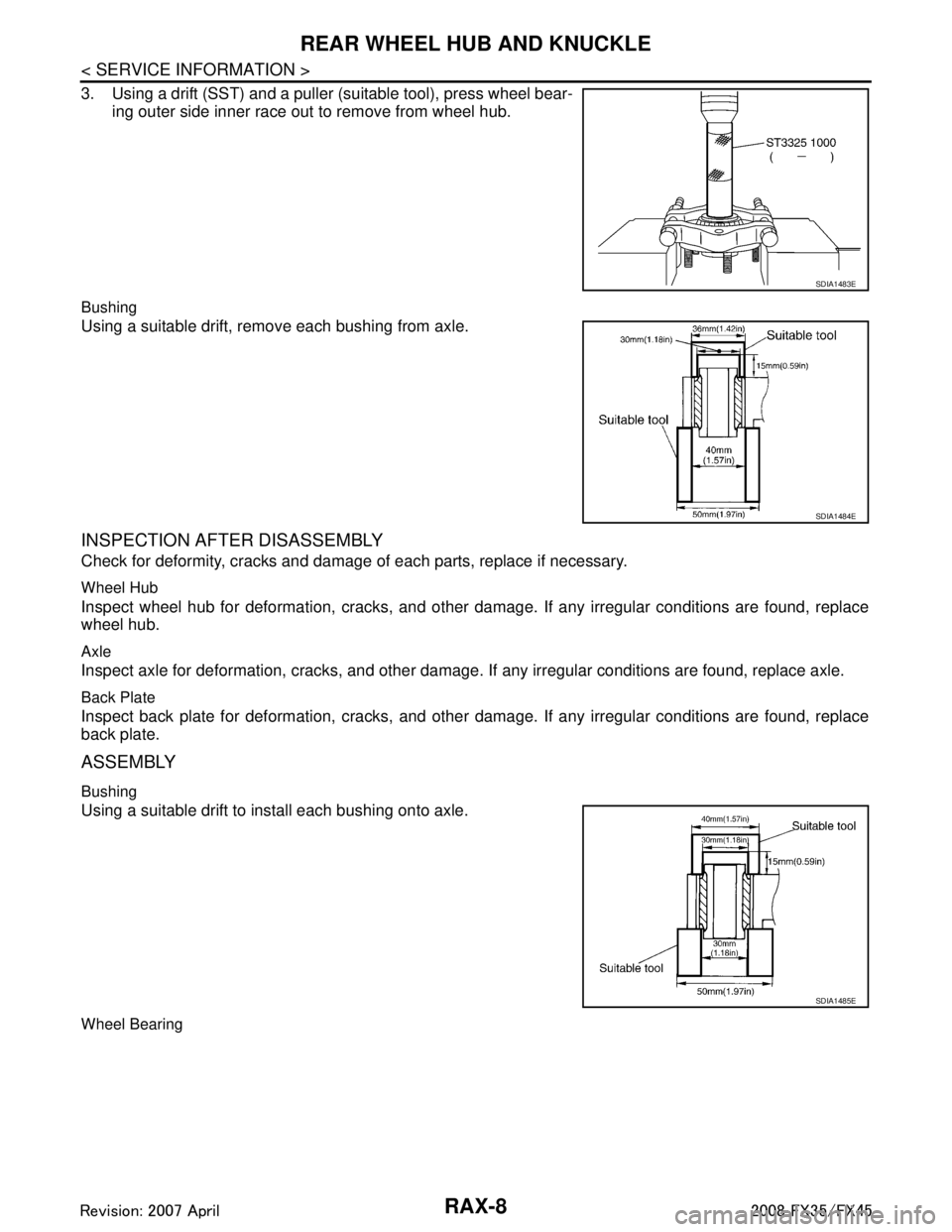
3. Using a drift (SST) and a puller (suitable tool), press wheel bear-ing outer side inner race out to remove from wheel hub.
Bushing
Using a suitable drift, remove each bushing from axle.
INSPECTION AFTER DISASSEMBLY
Check for deformity, cracks and damage of each parts, replace if necessary.
Wheel Hub
Inspect wheel hub for deformation, cracks, and other damag e. If any irregular conditions are found, replace
wheel hub.
Axle
Inspect axle for deformation, cracks, and other damage. If any irregular conditions are found, replace axle.
Back Plate
Inspect back plate for deformation, cracks, and other damage. If any irregular conditions are found, replace
back plate.
ASSEMBLY
Bushing
Using a suitable drift to install each bushing onto axle.
Wheel Bearing
SDIA1483E
SDIA1484E
SDIA1485E
3AA93ABC3ACD3AC03ACA3AC03AC63AC53A913A773A893A873A873A8E3A773A983AC73AC93AC03AC3
3A893A873A873A8F3A773A9D3AAF3A8A3A8C3A863A9D3AAF3A8B3A8C
Page 3507 of 3924
REAR WHEEL HUB AND KNUCKLERAX-9
< SERVICE INFORMATION >
CEF
G H
I
J
K L
M A
B
RAX
N
O P
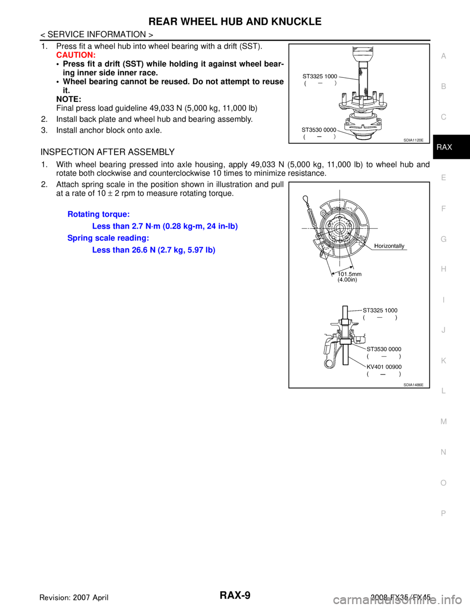
1. Press fit a wheel hub into wheel bearing with a drift (SST). CAUTION:
• Press fit a drift (SST) while ho lding it against wheel bear-
ing inner side inner race.
Wheel bearing cannot be reused. Do not attempt to reuse it.
NOTE:
Final press load guideline 49,033 N (5,000 kg, 11,000 lb)
2. Install back plate and wheel hub and bearing assembly.
3. Install anchor block onto axle.
INSPECTION AFTER ASSEMBLY
1. With wheel bearing pressed into axle housing, apply 49,033 N (5,000 kg, 11,000 lb) to wheel hub and rotate both clockwise and counterclockwise 10 times to minimize resistance.
2. Attach spring scale in the position shown in illustration and pull at a rate of 10 ± 2 rpm to measure rotating torque.
SDIA1120E
Rotating torque:
Less than 2.7 N·m (0.28 kg-m, 24 in-lb)
Spring scale reading: Less than 26.6 N (2.7 kg, 5.97 lb)
SDIA1486E
3AA93ABC3ACD3AC03ACA3AC03AC63AC53A913A773A893A873A873A8E3A773A983AC73AC93AC03AC3
3A893A873A873A8F3A773A9D3AAF3A8A3A8C3A863A9D3AAF3A8B3A8C