2008 INFINITI FX35 installation
[x] Cancel search: installationPage 3783 of 3924
SRS-46
< SERVICE INFORMATION >
OCCUPANT CLASSIFICATION SYSTEM CONTROL UNIT
OCCUPANT CLASSIFICATION SYSTEM CONTROL UNIT
Removal and InstallationINFOID:0000000001327772
The occupant classification system c ontrol unit, seat pressure sensor, and bladder are an integral part of the
front passenger seat cushion and are replaced as an assembly. Refer to SE-89, "
Removal and Installation".
3AA93ABC3ACD3AC03ACA3AC03AC63AC53A913A773A893A873A873A8E3A773A983AC73AC93AC03AC3
3A893A873A873A8F3A773A9D3AAF3A8A3A8C3A863A9D3AAF3A8B3A8C
Page 3787 of 3924

TF-1
DRIVELINE/AXLE
CEF
G H
I
J
K L
M
SECTION TF
A
B
TF
N
O P
CONTENTS
TRANSFER
SERVICE INFORMATION .. ..........................3
DTC INDEX ..................................................... .....3
C1201-C1210, U1000 ......................................... ......3
PRECAUTIONS ...................................................4
Precaution for Supplemental Restraint System
(SRS) "AIR BAG" and "SEAT BELT PRE-TEN-
SIONER" ............................................................. ......
4
Precaution .................................................................4
Service Notice or Precaution .....................................5
PREPARATION ...................................................6
Special Service Tool ........................................... ......6
Commercial Service Tool ..........................................7
NOISE, VIBRATION AND HARSHNESS
(NVH) TROUBLESHOOTING .............................
9
NVH Troubleshooting Chart ................................ ......9
TRANSFER FLUID .............................................10
Replacement ....................................................... ....10
Inspection ................................................................10
AWD SYSTEM ................................................ ....11
Power Transfer Diagram ..................................... ....11
System Description .................................................11
Schematic ...............................................................13
CAN Communication ...............................................13
TROUBLE DIAGNOSIS .....................................14
Fail-Safe Function ............................................... ....14
How to Perform Trouble Diagnosis .........................14
Location of Electrical Parts ......................................15
Circuit Diagram .......................................................16
Wiring Diagram - AWD - ..........................................17
Trouble Diagnosis Chart by Symptom ....................20
AWD Control Unit Input/Output Signal Reference
Value ................................................................... ....
20
CONSULT-III Function (ALL MODE AWD/4WD) ....21
TROUBLE DIAGNOSIS FOR SYSTEM .............24
DTC C1201 CONTROLLER FAILURE ................ ....24
DTC C1203 ABS SYSTEM ......................................24
DTC C1204 4WD SOLENOID ............................. ....25
DTC C1205 4WD ACTUATOR RLY ........................27
DTC C1210 ENGINE SIGNAL 1 ..............................28
DTC U1000 CAN COMM CIRCUIT .........................28
Power Supply Circuit for AWD Control Unit .............28
TROUBLE DIAGNOSIS FOR SYMPTOMS ......30
AWD Warning Lamp Does Not Turn ON When the
Ignition Switch Is Turned to ON ...............................
30
AWD Warning Lamp Does Not Turn OFF Several
Seconds after Engine Started ..................................
30
Heavy Tight-Corner Braking Symptom Occurs
When the Vehicle Is Driven and the Steering
Wheel Is Turned Fully to Either Side after the En-
gine Is Started .........................................................
32
Vehicle Does Not Enter AWD Mode Even Though
AWD Warning Lamp Turned to OFF .......................
33
While Driving, AWD Warning Lamp Flashes Rap-
idly (When Flashing in Approx. 1 Minute and Then
Turning OFF) ....................................................... ....
33
While Driving, AWD Warning Lamp Flashes Slow-
ly (When Continuing to Flash until Turning Ignition
Switch OFF) .............................................................
33
AWD CONTROL UNIT ......................................35
Removal and Installation .........................................35
FRONT OIL SEAL .............................................36
Removal and Installation .........................................36
REAR OIL SEAL ...............................................37
Removal and Installation .........................................37
AIR BREATHER HOSE ....................................39
Removal and Installation .........................................39
TRANSFER ASSEMBLY ..................................40
Removal and Installation .........................................40
Disassembly and Assembly .....................................40
3AA93ABC3ACD3AC03ACA3AC03AC63AC53A913A773A893A873A873A8E3A773A983AC73AC93AC03AC3
3A893A873A873A8F3A773A9D3AAF3A8A3A8C3A863A9D3AAF3A8B3A8C
Page 3790 of 3924

TF-4
< SERVICE INFORMATION >
PRECAUTIONS
PRECAUTIONS
Precaution for Supplemental Restraint System (SRS) "AIR BAG" and "SEAT BELT
PRE-TENSIONER"
INFOID:0000000001612930
The Supplemental Restraint System such as “A IR BAG” and “SEAT BELT PRE-TENSIONER”, used along
with a front seat belt, helps to reduce the risk or severi ty of injury to the driver and front passenger for certain
types of collision. This system includes seat belt switch inputs and dual stage front air bag modules. The SRS
system uses the seat belt switches to determine the front air bag deployment, and may only deploy one front
air bag, depending on the severity of a collision and w hether the front occupants are belted or unbelted.
Information necessary to service the system safely is included in the “SUPPLEMENTAL RESTRAINT SYS-
TEM” and “SEAT BELTS” of this Service Manual.
WARNING:
• To avoid rendering the SRS inopera tive, which could increase the risk of personal injury or death in
the event of a collision which would result in air bag inflation, all maintenance must be performed by
an authorized NISS AN/INFINITI dealer.
Improper maintenance, including in correct removal and installation of the SRS, can lead to personal
injury caused by unintent ional activation of the system. For re moval of Spiral Cable and Air Bag
Module, see the “SUPPLEMEN TAL RESTRAINT SYSTEM”.
Do not use electrical test equipmen t on any circuit related to the SRS unless instructed to in this
Service Manual. SRS wiring harnesses can be identi fied by yellow and/or orange harnesses or har-
ness connectors.
PrecautionINFOID:0000000001327424
Before connecting or disconnect ing the AWD control unit har-
ness connector, turn ignition switch “OFF” and disconnect
battery ground cable. Because battery voltage is applied to
AWD control unit even if igni tion switch is turned “OFF”.
When connecting or disconnect ing pin connectors into or
from AWD control unit, take care not to damage pin terminals
(bend or break).
When connecting pin connectors, make sure that there are no
bends or breaks on AWD control unit pin terminal.
SEF289H
SEF291H
3AA93ABC3ACD3AC03ACA3AC03AC63AC53A913A773A893A873A873A8E3A773A983AC73AC93AC03AC3
3A893A873A873A8F3A773A9D3AAF3A8A3A8C3A863A9D3AAF3A8B3A8C
Page 3791 of 3924
PRECAUTIONSTF-5
< SERVICE INFORMATION >
CEF
G H
I
J
K L
M A
B
TF
N
O P
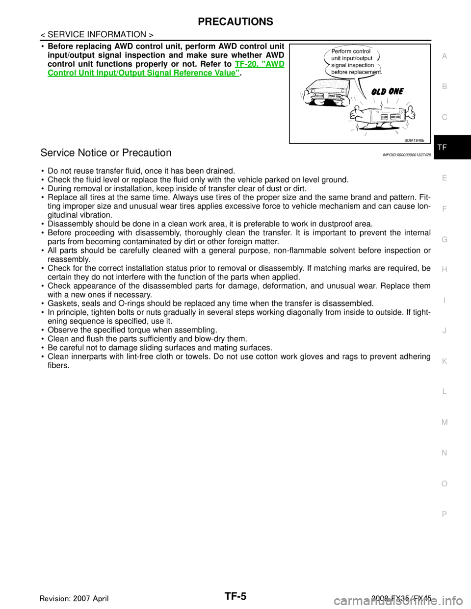
Before replacing AWD control unit, perform AWD control unit
input/output signal inspection and make sure whether AWD
control unit functions properly or not. Refer to TF-20, "
AW D
Control Unit Input/Output Signal Reference Value".
Service Notice or PrecautionINFOID:0000000001327425
Do not reuse transfer fluid, once it has been drained.
Check the fluid level or replace the fluid only with the vehicle parked on level ground.
During removal or installation, keep inside of transfer clear of dust or dirt.
Replace all tires at the same time. Always use tires of the proper size and the same brand and pattern. Fit-
ting improper size and unusual wear tires applies excessive force to vehicle mechanism and can cause lon-
gitudinal vibration.
Disassembly should be done in a clean work area, it is preferable to work in dustproof area.
Before proceeding with disassembly, thoroughly clean the tr ansfer. It is important to prevent the internal
parts from becoming contaminated by dirt or other foreign matter.
All parts should be carefully cleaned with a general purpose, non-flammable solvent before inspection or
reassembly.
Check for the correct installation status prior to remo val or disassembly. If matching marks are required, be
certain they do not interfere with t he function of the parts when applied.
Check appearance of the disassembled parts for dam age, deformation, and unusual wear. Replace them
with a new ones if necessary.
Gaskets, seals and O-rings should be replaced any time when the transfer is disassembled.
In principle, tighten bolts or nuts gradually in several steps working diagonally from inside to outside. If tight-
ening sequence is specified, use it.
Observe the specified torque when assembling.
Clean and flush the parts sufficiently and blow-dry them.
Be careful not to damage sliding surfaces and mating surfaces.
Clean innerparts with lint-free cloth or towels. Do not use cotton work gloves and rags to prevent adhering
fibers.
SDIA1848E
3AA93ABC3ACD3AC03ACA3AC03AC63AC53A913A773A893A873A873A8E3A773A983AC73AC93AC03AC3
3A893A873A873A8F3A773A9D3AAF3A8A3A8C3A863A9D3AAF3A8B3A8C
Page 3821 of 3924
AWD CONTROL UNITTF-35
< SERVICE INFORMATION >
CEF
G H
I
J
K L
M A
B
TF
N
O P
AWD CONTROL UNIT
Removal and InstallationINFOID:0000000001327456
REMOVAL
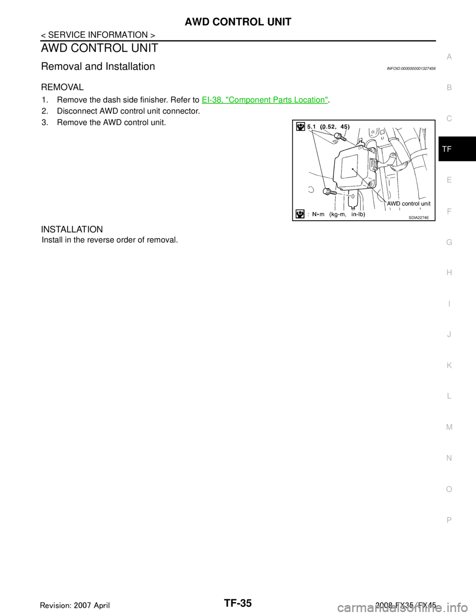
1. Remove the dash side finisher. Refer to EI-38, "Component Parts Location".
2. Disconnect AWD control unit connector.
3. Remove the AWD control unit.
INSTALLATION
Install in the reverse order of removal.
SDIA2274E
3AA93ABC3ACD3AC03ACA3AC03AC63AC53A913A773A893A873A873A8E3A773A983AC73AC93AC03AC3
3A893A873A873A8F3A773A9D3AAF3A8A3A8C3A863A9D3AAF3A8B3A8C
Page 3822 of 3924
TF-36
< SERVICE INFORMATION >
FRONT OIL SEAL
FRONT OIL SEAL
Removal and InstallationINFOID:0000000001327457
REMOVAL
1. Remove the drain plug to drain the transfer fluid. Refer to TF-10, "Replacement".
2. Remove the front propeller shaft. Refer to PR-4
.
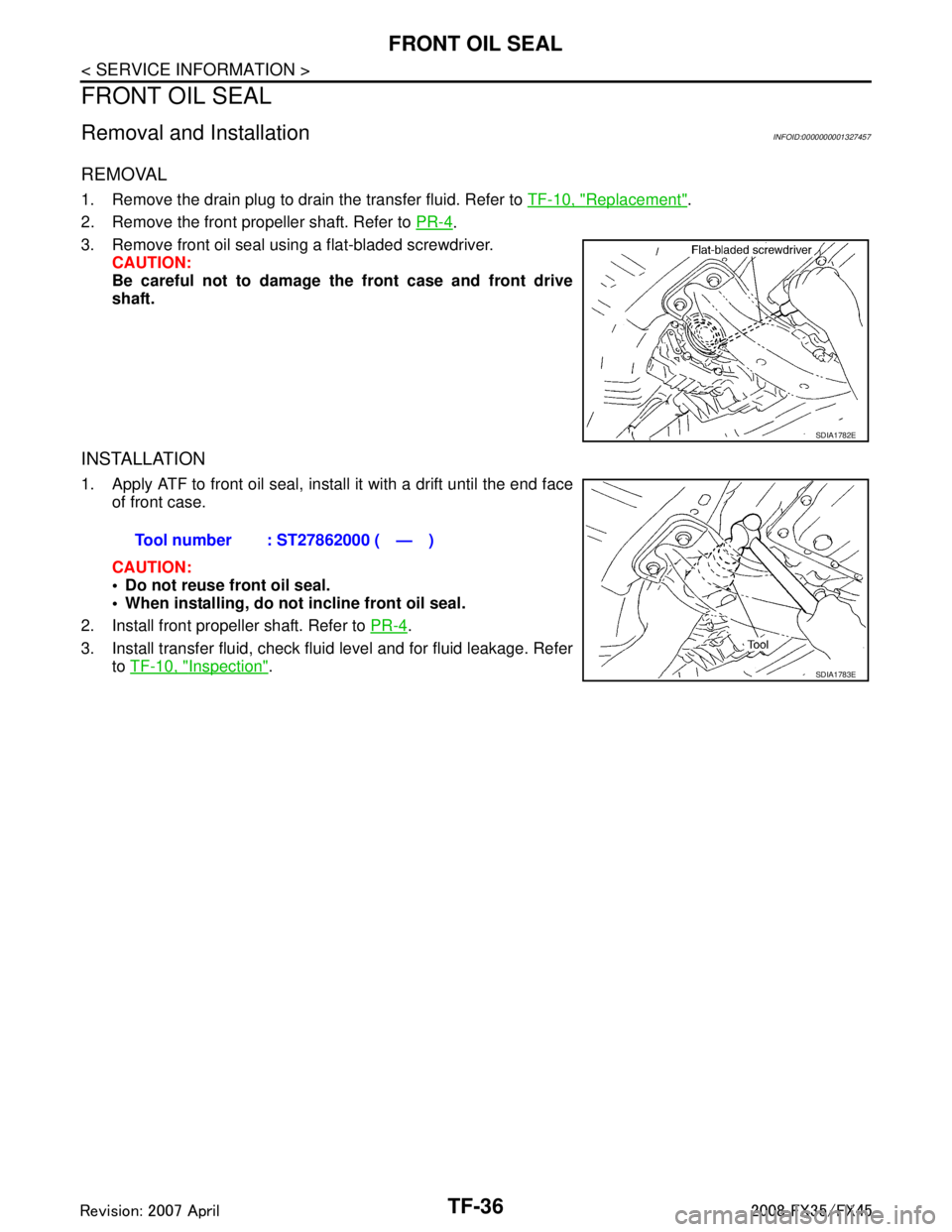
3. Remove front oil seal using a flat-bladed screwdriver. CAUTION:
Be careful not to damage the front case and front drive
shaft.
INSTALLATION
1. Apply ATF to front oil seal, install it with a drift until the end faceof front case.
CAUTION:
Do not reuse front oil seal.
When installing, do no t incline front oil seal.
2. Install front propeller shaft. Refer to PR-4
.
3. Install transfer fluid, check fluid level and for fluid leakage. Refer to TF-10, "
Inspection".
SDIA1782E
Tool number : ST27862000 ( — )
SDIA1783E
3AA93ABC3ACD3AC03ACA3AC03AC63AC53A913A773A893A873A873A8E3A773A983AC73AC93AC03AC3
3A893A873A873A8F3A773A9D3AAF3A8A3A8C3A863A9D3AAF3A8B3A8C
Page 3823 of 3924
REAR OIL SEALTF-37
< SERVICE INFORMATION >
CEF
G H
I
J
K L
M A
B
TF
N
O P
REAR OIL SEAL
Removal and InstallationINFOID:0000000001327458
REMOVAL
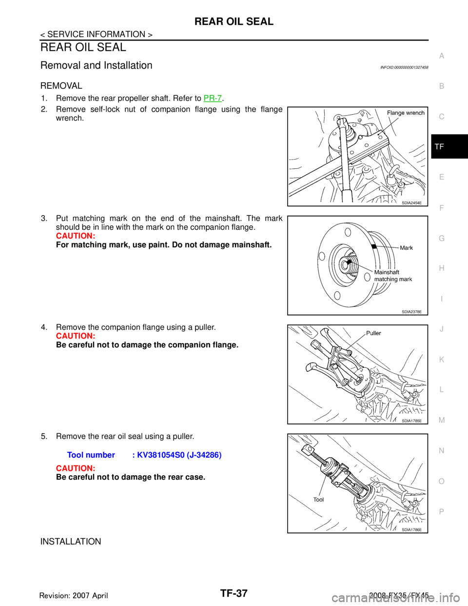
1. Remove the rear propeller shaft. Refer to PR-7.
2. Remove self-lock nut of companion flange using the flange wrench.
3. Put matching mark on the end of the mainshaft. The mark should be in line with the mark on the companion flange.
CAUTION:
For matching mark, use paint. Do not damage mainshaft.
4. Remove the companion flange using a puller. CAUTION:
Be careful not to damage the companion flange.
5. Remove the rear oil seal using a puller. CAUTION:
Be careful not to damage the rear case.
INSTALLATION
SDIA2454E
SDIA2378E
SDIA1785E
Tool number : KV381054S0 (J-34286)
SDIA1786E
3AA93ABC3ACD3AC03ACA3AC03AC63AC53A913A773A893A873A873A8E3A773A983AC73AC93AC03AC3
3A893A873A873A8F3A773A9D3AAF3A8A3A8C3A863A9D3AAF3A8B3A8C
Page 3825 of 3924
AIR BREATHER HOSETF-39
< SERVICE INFORMATION >
CEF
G H
I
J
K L
M A
B
TF
N
O P
AIR BREATHER HOSE
Removal and InstallationINFOID:0000000001327459
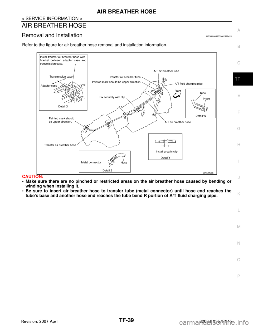
Refer to the figure for air breather hose removal and installation information.
CAUTION:
Make sure there are no pinched or restricted areas on the air breather hose caused by bending or
winding when installing it.
Be sure to insert air breather hose to transfer tube (metal connector) until hose end reaches the
tube's base and another hose end reaches the tube bend R portion of A/T fluid charging pipe.
SDIA2408E
3AA93ABC3ACD3AC03ACA3AC03AC63AC53A913A773A893A873A873A8E3A773A983AC73AC93AC03AC3
3A893A873A873A8F3A773A9D3AAF3A8A3A8C3A863A9D3AAF3A8B3A8C