2008 INFINITI FX35 installation
[x] Cancel search: installationPage 3641 of 3924

SE-2
Description ..............................................................86
Wiring Diagram - HSEAT - .....................................87
FRONT SEAT ................................................. ...89
Removal and Installation ...................................... ...89
REAR SEAT ......................................................95
Removal and Installation ...................................... ...95
3AA93ABC3ACD3AC03ACA3AC03AC63AC53A913A773A893A873A873A8E3A773A983AC73AC93AC03AC3
3A893A873A873A8F3A773A9D3AAF3A8A3A8C3A863A9D3AAF3A8B3A8C
Page 3643 of 3924
SE-4
< SERVICE INFORMATION >
PRECAUTIONS
PRECAUTIONS
Precaution for Supplemental Restraint System (SRS) "AIR BAG" and "SEAT BELT
PRE-TENSIONER"
INFOID:0000000001612906
The Supplemental Restraint System such as “A IR BAG” and “SEAT BELT PRE-TENSIONER”, used along
with a front seat belt, helps to reduce the risk or severi ty of injury to the driver and front passenger for certain
types of collision. This system includes seat belt switch inputs and dual stage front air bag modules. The SRS
system uses the seat belt switches to determine the front air bag deployment, and may only deploy one front
air bag, depending on the severity of a collision and w hether the front occupants are belted or unbelted.
Information necessary to service the system safely is included in the “SUPPLEMENTAL RESTRAINT SYS-
TEM” and “SEAT BELTS” of this Service Manual.
WARNING:
• To avoid rendering the SRS inopera tive, which could increase the risk of personal injury or death in
the event of a collision which would result in air bag inflation, all maintenance must be performed by
an authorized NISS AN/INFINITI dealer.
Improper maintenance, including in correct removal and installation of the SRS, can lead to personal
injury caused by unintent ional activation of the system. For re moval of Spiral Cable and Air Bag
Module, see the “SUPPLEMEN TAL RESTRAINT SYSTEM”.
Do not use electrical test equipmen t on any circuit related to the SRS unless instructed to in this
Service Manual. SRS wiring harnesses can be identi fied by yellow and/or orange harnesses or har-
ness connectors.
Service NoticeINFOID:0000000001328091
When removing or installing various parts, place a cloth or padding onto the vehicle body to prevent
scratches.
Handle trim, molding, instruments, grille, etc. carefull y during removing or installing. Be careful not to oil or
damage them.
Apply sealing compound where necessary when installing parts.
When applying sealing compound, be careful that the sealing compound does not protrude from parts.
When replacing any metal parts (for example body outer panel, members, etc.), be sure to take rust preven-
tion measures.
3AA93ABC3ACD3AC03ACA3AC03AC63AC53A913A773A893A873A873A8E3A773A983AC73AC93AC03AC3
3A893A873A873A8F3A773A9D3AAF3A8A3A8C3A863A9D3AAF3A8B3A8C
Page 3647 of 3924
SE-8
< SERVICE INFORMATION >
SQUEAK AND RATTLE TROUBLE DIAGNOSES
Insulates where slight movement is present. Ideal for instrument panel applications.
SILICONE GREASE
Used in place of UHMW tape that will be visible or not fit.
Note: Will only last a few months.
SILICONE SPRAY
Use when grease cannot be applied.
DUCT TAPE
Use to eliminate movement.
CONFIRM THE REPAIR
Confirm that the cause of a noise is repaired by test driving the vehicle. Operate the vehicle under the same
conditions as when the noise originally occurred. Refer to the notes on the Diagnostic Worksheet.
Generic Squeak and Rattle TroubleshootingINFOID:0000000001328095
Refer to Table of Contents for specific component removal and installation information.
INSTRUMENT PANEL
Most incidents are caused by contact and movement between:
1. The cluster lid A and instrument panel
2. Acrylic lens and combination meter housing
3. Instrument panel to front pillar garnish
4. Instrument panel to windshield
5. Instrument panel mounting pins
6. Wiring harnesses behind the combination meter
7. A/C defroster duct and duct joint
These incidents can usually be located by tapping or moving the components to duplicate the noise or by
pressing on the components while driving to stop the noi se. Most of these incidents can be repaired by apply-
ing felt cloth tape or silicon spray (in hard to reach areas). Urethane pads can be used to insulate wiring har-
ness.
CAUTION:
Do not use silicone spray to isolate a squeak or ra ttle. If you saturate the area with silicone, you will
not be able to recheck the repair.
CENTER CONSOLE
Components to pay attention to include:
1. Shifter assembly cover to finisher
2. A/C control unit and cluster lid C
3. Wiring harnesses behind audio and A/C control unit
The instrument panel repair and isolation pr ocedures also apply to the center console.
DOORS
Pay attention to the:
1. Finisher and inner panel making a slapping noise
2. Inside handle escutcheon to door finisher
3. Wiring harnesses tapping
4. Door striker out of alignment causing a popping noise on starts and stops
Tapping or moving the components or pressing on them wh ile driving to duplicate the conditions can isolate
many of these incidents. You can usually insulate the areas with felt cloth tape or insulator foam blocks from
the Nissan Squeak and Rattle Kit (J-43980) to repair the noise.
TRUNK
Trunk noises are often caused by a loose jack or loose items put into the trunk by the owner.
In addition look for:
1. Trunk lid dumpers out of adjustment
2. Trunk lid striker out of adjustment
3. The trunk lid torsion bars knocking together
4. A loose license plate or bracket
3AA93ABC3ACD3AC03ACA3AC03AC63AC53A913A773A893A873A873A8E3A773A983AC73AC93AC03AC3
3A893A873A873A8F3A773A9D3AAF3A8A3A8C3A863A9D3AAF3A8B3A8C
Page 3683 of 3924
SE-44
< SERVICE INFORMATION >
AUTOMATIC DRIVE POSITIONER
Check Sliding Motor Circuit
INFOID:0000000001328111
1.CHECK SEAT SLIDING MECHANISM
Check the following.
Operation malfunction caused by sliding rail deformation or pinched harness or other foreign materials
Operation malfunction caused by foreign materials adhered to the sliding motor or sliding rail connector rod
Operation malfunction and interference wit h other parts by poor installation
OK or NG
OK >> GO TO 2 (With CONSULT-III). GO TO 3 (Without CONSULT-III).
NG >> Repair the malfunctioning part and check again.
2.CHECK FUNCTION
With CONSULT-III
Check operation with “SEAT SLIDE” in ACTIVE TEST.
OK or NG
OK >> Sliding motor circuit is OK.
NG >> GO TO 3.
3.CHECK SLIDING MOTOR HARNESS CONTINUITY
1. Turn ignition switch OFF.
2. Disconnect driver seat control unit connector and sliding motor connector.
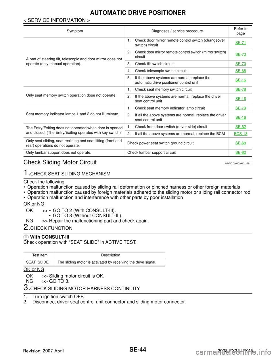
A part of steering tilt, telescopic and door mirror does not
operate (only manual operation). 1. Check door mirror remote
control switch (changeover
switch) circuit SE-71
2. Check door mirror remote co
ntrol switch (mirror switch)
circuit SE-73
3. Check tilt switch circuit
SE-70
4. Check telescopic switch circuitSE-68
5. If the above systems are normal, replace the
automatic drive positioner control unit SE-16
Only seat memory switch operation dose not operate. 1. Check seat memory switch circuit
SE-782. If the above systems are normal, replace the driver
seat control unit SE-16
Seat memory indicator lamps 1 and 2 do not illuminate. 1. Check seat memory indicator lamp circuit
SE-792. If all the above systems are normal, replace the driver
seat control unit SE-16
The Entry/Exiting does not operated when door is opened
and closed. (The Entry/Exiting operates with key switch) 1. Check front door switch
(driver side) circuit SE-62
2. If all the above systems are normal, replace the BCM BCS-13
Only seat sliding, seat reclining and seat lifting (front and
rear) operations do not operate.Check power seat switch ground circuit
SE-68
Only lumbar support does not operate. Check lumbar support circuit SE-82
Symptom Diagnoses / service procedureRefer to
page
Test item Description
SEAT SLIDE The sliding motor is activated by receiving the drive signal.
3AA93ABC3ACD3AC03ACA3AC03AC63AC53A913A773A893A873A873A8E3A773A983AC73AC93AC03AC3
3A893A873A873A8F3A773A9D3AAF3A8A3A8C3A863A9D3AAF3A8B3A8C
Page 3684 of 3924
AUTOMATIC DRIVE POSITIONERSE-45
< SERVICE INFORMATION >
C
DE
F
G H
J
K L
M A
B
SE
N
O P
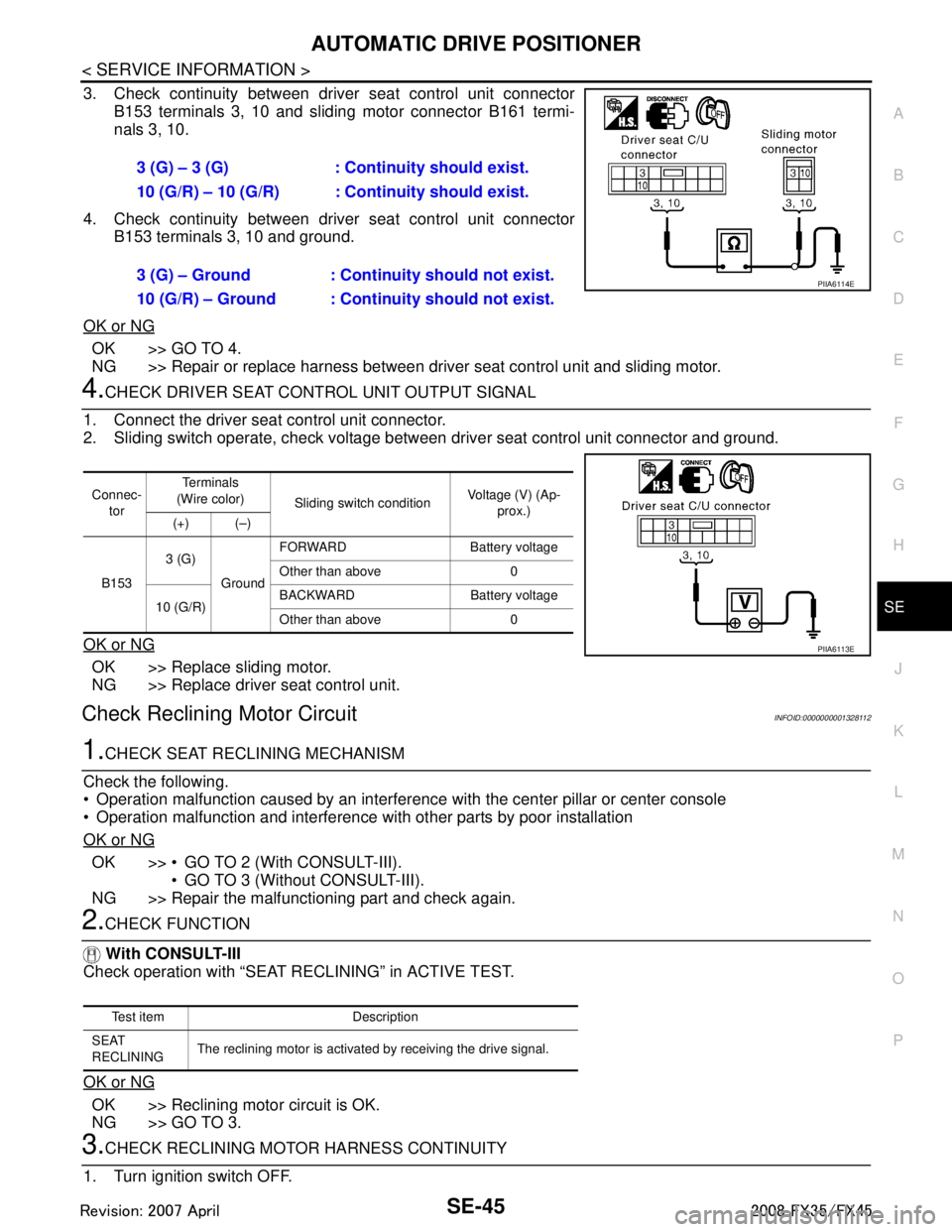
3. Check continuity between driver seat control unit connector B153 terminals 3, 10 and sliding motor connector B161 termi-
nals 3, 10.
4. Check continuity between driver seat control unit connector B153 terminals 3, 10 and ground.
OK or NG
OK >> GO TO 4.
NG >> Repair or replace harness between driver seat control unit and sliding motor.
4.CHECK DRIVER SEAT CONTROL UNIT OUTPUT SIGNAL
1. Connect the driver seat control unit connector.
2. Sliding switch operate, check voltage betw een driver seat control unit connector and ground.
OK or NG
OK >> Replace sliding motor.
NG >> Replace driver seat control unit.
Check Reclining Motor CircuitINFOID:0000000001328112
1.CHECK SEAT RECLINING MECHANISM
Check the following.
Operation malfunction caused by an interference with the center pillar or center console
Operation malfunction and interference with other parts by poor installation
OK or NG
OK >> GO TO 2 (With CONSULT-III). GO TO 3 (Without CONSULT-III).
NG >> Repair the malfunctioning part and check again.
2.CHECK FUNCTION
With CONSULT-III
Check operation with “SEAT RECLINING” in ACTIVE TEST.
OK or NG
OK >> Reclining motor circuit is OK.
NG >> GO TO 3.
3.CHECK RECLINING MOTOR HARNESS CONTINUITY
1. Turn ignition switch OFF. 3 (G) – 3 (G) : Continuity should exist.
10 (G/R) – 10 (G/R) : Continuity should exist.
3 (G) – Ground : Continuity should not exist.
10 (G/R) – Ground : Continuity should not exist.
PIIA6114E
Connec-
tor Te r m i n a l s
(Wire color) Sliding switch condition Voltage (V) (Ap-
prox.)
(+) (–)
B153 3 (G)
Ground FORWARD Battery voltage
Other than above 0
10 (G/R) BACKWARD Battery voltage
Other than above 0
PIIA6113E
Test item Description
SEAT
RECLINING The reclining motor is activated by receiving the drive signal.
3AA93ABC3ACD3AC03ACA3AC03AC63AC53A913A773A893A873A873A8E3A773A983AC73AC93AC03AC3
3A893A873A873A8F3A773A9D3AAF3A8A3A8C3A863A9D3AAF3A8B3A8C
Page 3685 of 3924
SE-46
< SERVICE INFORMATION >
AUTOMATIC DRIVE POSITIONER
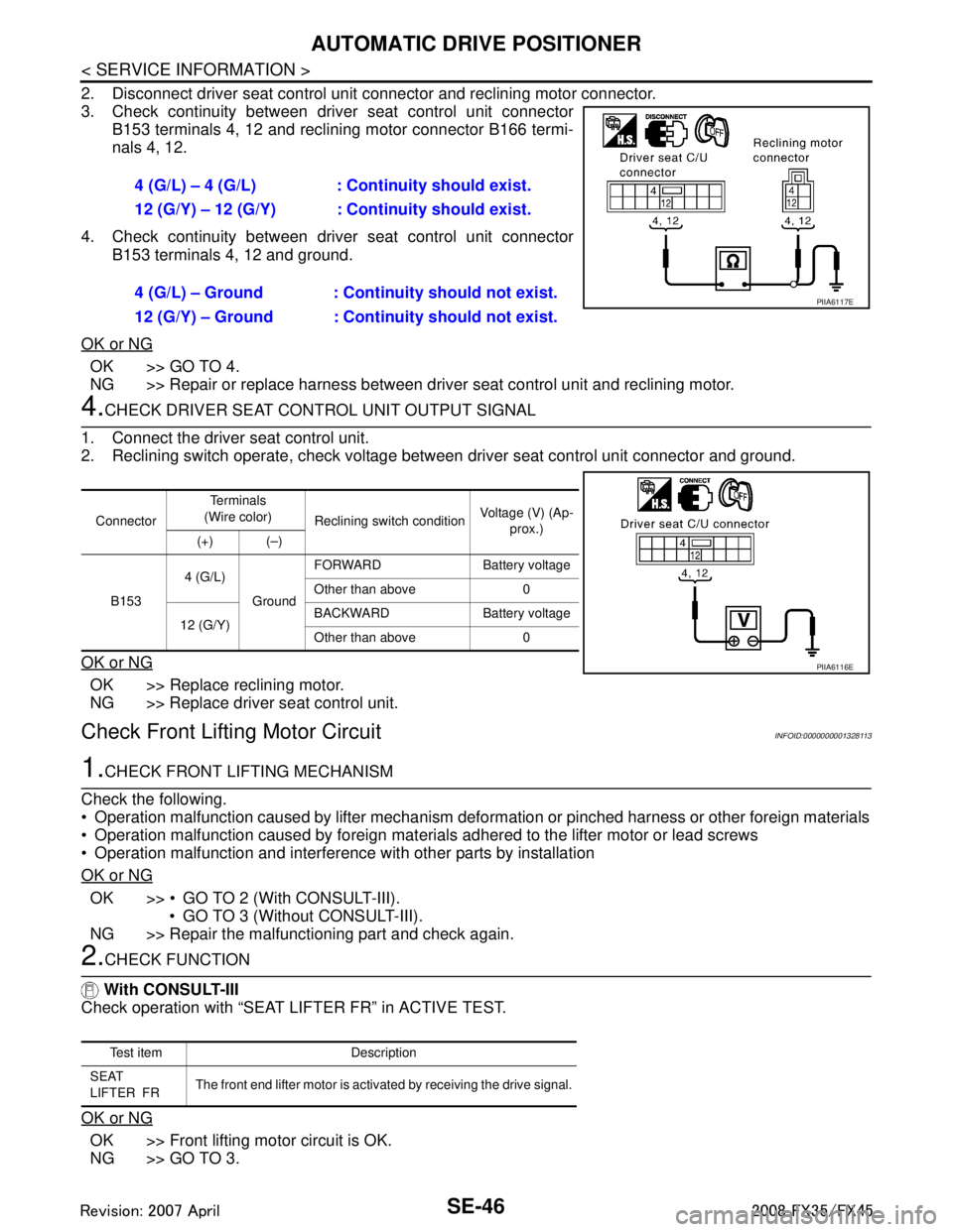
2. Disconnect driver seat control unit connector and reclining motor connector.
3. Check continuity between driver seat control unit connector
B153 terminals 4, 12 and reclining motor connector B166 termi-
nals 4, 12.
4. Check continuity between driv er seat control unit connector
B153 terminals 4, 12 and ground.
OK or NG
OK >> GO TO 4.
NG >> Repair or replace harness between driver seat control unit and reclining motor.
4.CHECK DRIVER SEAT CONTROL UNIT OUTPUT SIGNAL
1. Connect the driver seat control unit.
2. Reclining switch operate, check voltage between driver seat control unit connector and ground.
OK or NG
OK >> Replace reclining motor.
NG >> Replace driver seat control unit.
Check Front Lifting Motor CircuitINFOID:0000000001328113
1.CHECK FRONT LIFTING MECHANISM
Check the following.
Operation malfunction caused by lifter mechanism defo rmation or pinched harness or other foreign materials
Operation malfunction caused by foreign materials adhered to the lifter motor or lead screws
Operation malfunction and interference with other parts by installation
OK or NG
OK >> GO TO 2 (With CONSULT-III). GO TO 3 (Without CONSULT-III).
NG >> Repair the malfunctioning part and check again.
2.CHECK FUNCTION
With CONSULT-III
Check operation with “SEAT LIFTER FR” in ACTIVE TEST.
OK or NG
OK >> Front lifting motor circuit is OK.
NG >> GO TO 3. 4 (G/L) – 4 (G/L) : Co
ntinuity should exist.
12 (G/Y) – 12 (G/Y) : Co ntinuity should exist.
4 (G/L) – Ground : Continuity should not exist.
12 (G/Y) – Ground : Continuity should not exist.
PIIA6117E
Connector Te r m i n a l s
(Wire color) Reclining switch condition Voltage (V) (Ap-
prox.)
(+) (–)
B153 4 (G/L)
GroundFORWARD Battery voltage
Other than above 0
12 (G/Y) BACKWARD Battery voltage
Other than above 0
PIIA6116E
Te s t i t e m D e s c r i p t i o n
SEAT
LIFTER FR The front end lifter motor is activated by receiving the drive signal.
3AA93ABC3ACD3AC03ACA3AC03AC63AC53A913A773A893A873A873A8E3A773A983AC73AC93AC03AC3
3A893A873A873A8F3A773A9D3AAF3A8A3A8C3A863A9D3AAF3A8B3A8C
Page 3686 of 3924
AUTOMATIC DRIVE POSITIONERSE-47
< SERVICE INFORMATION >
C
DE
F
G H
J
K L
M A
B
SE
N
O P
3.CHECK FRONT LIFTING MO TOR HARNESS CONTINUITY
1. Turn ignition switch OFF.
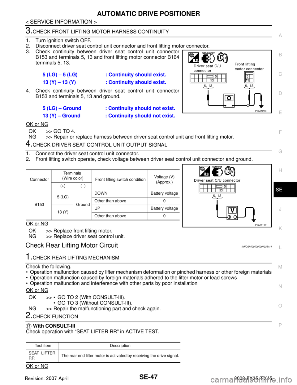
2. Disconnect driver seat control unit connector and front lifting motor connector.
3. Check continuity between driver seat control unit connector B153 and terminals 5, 13 and front lifting motor connector B164
terminals 5, 13.
4. Check continuity between driver seat control unit connector B153 and terminals 5, 13 and ground.
OK or NG
OK >> GO TO 4.
NG >> Repair or replace harness between driver seat control unit and front lifting motor.
4.CHECK DRIVER SEAT CONTROL UNIT OUTPUT SIGNAL
1. Connect the driver seat control unit connector.
2. Front lifting switch operate, check voltage bet ween driver seat control unit connector and ground.
OK or NG
OK >> Replace front lifting motor.
NG >> Replace driver seat control unit.
Check Rear Lifting Motor CircuitINFOID:0000000001328114
1.CHECK REAR LIFTING MECHANISM
Check the following.
Operation malfunction caused by lifter mechanism deformation or pinched harness or other foreign materials
Operation malfunction caused by foreign materials adhered to the lifter motor or lead screws
Operation malfunction and interference with other parts by poor installation
OK or NG
OK >> GO TO 2 (With CONSULT-III). GO TO 3 (Without CONSULT-III).
NG >> Repair the malfunctioning part and check again.
2.CHECK FUNCTION
With CONSULT-III
Check operation with “SEAT LIFTER RR” in ACTIVE TEST.
OK or NG
5 (LG) – 5 (LG) : Cont inuity should exist.
13 (Y) – 13 (Y) : Continuity should exist.
5 (LG) – Ground : Contin uity should not exist.
13 (Y) – Ground : Continuity should not exist.
PIIA6120E
Connector Te r m i n a l s
(Wire color) Front lifting switch condition Voltage (V)
(Approx.)
(+) (–)
B153 5 (LG)
GroundDOWN Battery voltage
Other than above 0
13 (Y) UP Battery voltage
Other than above 0
PIIA6119E
Test item Description
SEAT LIFTER
RR The rear end lifter motor is activated by receiving the drive signal.
3AA93ABC3ACD3AC03ACA3AC03AC63AC53A913A773A893A873A873A8E3A773A983AC73AC93AC03AC3
3A893A873A873A8F3A773A9D3AAF3A8A3A8C3A863A9D3AAF3A8B3A8C
Page 3687 of 3924
SE-48
< SERVICE INFORMATION >
AUTOMATIC DRIVE POSITIONER
OK >> Rear lifting motor check is OK.
NG >> GO TO 3.
3.CHECK REAR LIFTING HARNESS CONTINUITY
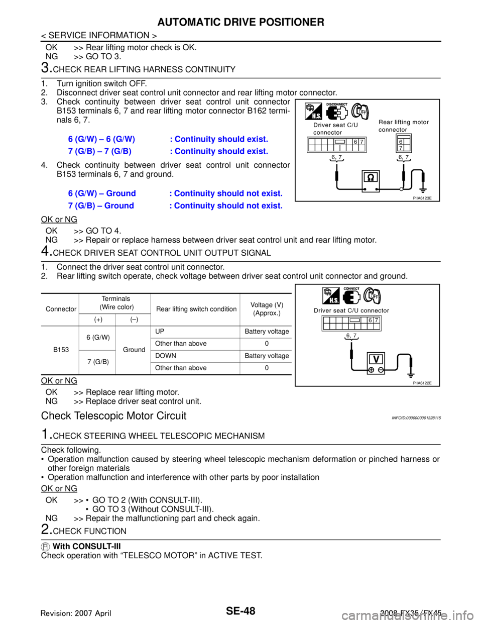
1. Turn ignition switch OFF.
2. Disconnect driver seat control unit connector and rear lifting motor connector.
3. Check continuity between driv er seat control unit connector
B153 terminals 6, 7 and rear lifting motor connector B162 termi-
nals 6, 7.
4. Check continuity between driv er seat control unit connector
B153 terminals 6, 7 and ground.
OK or NG
OK >> GO TO 4.
NG >> Repair or replace harness between driver seat control unit and rear lifting motor.
4.CHECK DRIVER SEAT CONTROL UNIT OUTPUT SIGNAL
1. Connect the driver seat control unit connector.
2. Rear lifting switch operate, check voltage between driver seat control unit connector and ground.
OK or NG
OK >> Replace rear lifting motor.
NG >> Replace driver seat control unit.
Check Telescopic Motor CircuitINFOID:0000000001328115
1.CHECK STEERING WHEEL TELESCOPIC MECHANISM
Check following.
Operation malfunction caused by steering wheel telescopic mechanism deformation or pinched harness or other foreign materials
Operation malfunction and interference wit h other parts by poor installation
OK or NG
OK >> GO TO 2 (With CONSULT-III). GO TO 3 (Without CONSULT-III).
NG >> Repair the malfunctioning part and check again.
2.CHECK FUNCTION
With CONSULT-III
Check operation with “TELESCO MOTOR” in ACTIVE TEST. 6 (G/W) – 6 (G/W) : Co
ntinuity should exist.
7 (G/B) – 7 (G/B) : Co ntinuity should exist.
6 (G/W) – Ground : Continuity should not exist.
7 (G/B) – Ground : Continuity should not exist.
PIIA6123E
Connector Te r m i n a l s
(Wire color) Rear lifting switch condition Voltage (V)
(Approx.)
(+) (–)
B153 6 (G/W)
GroundUP Battery voltage
Other than above 0
7 (G/B) DOWN Battery voltage
Other than above 0
PIIA6122E
3AA93ABC3ACD3AC03ACA3AC03AC63AC53A913A773A893A873A873A8E3A773A983AC73AC93AC03AC3
3A893A873A873A8F3A773A9D3AAF3A8A3A8C3A863A9D3AAF3A8B3A8C