2008 INFINITI FX35 installation
[x] Cancel search: installationPage 3604 of 3924
SEAT BELTSSB-5
< SERVICE INFORMATION >
C
DE
F
G
I
J
K L
M A
B
SB
N
O P
Removal and Installati on of Rear Seat BeltINFOID:0000000001327736
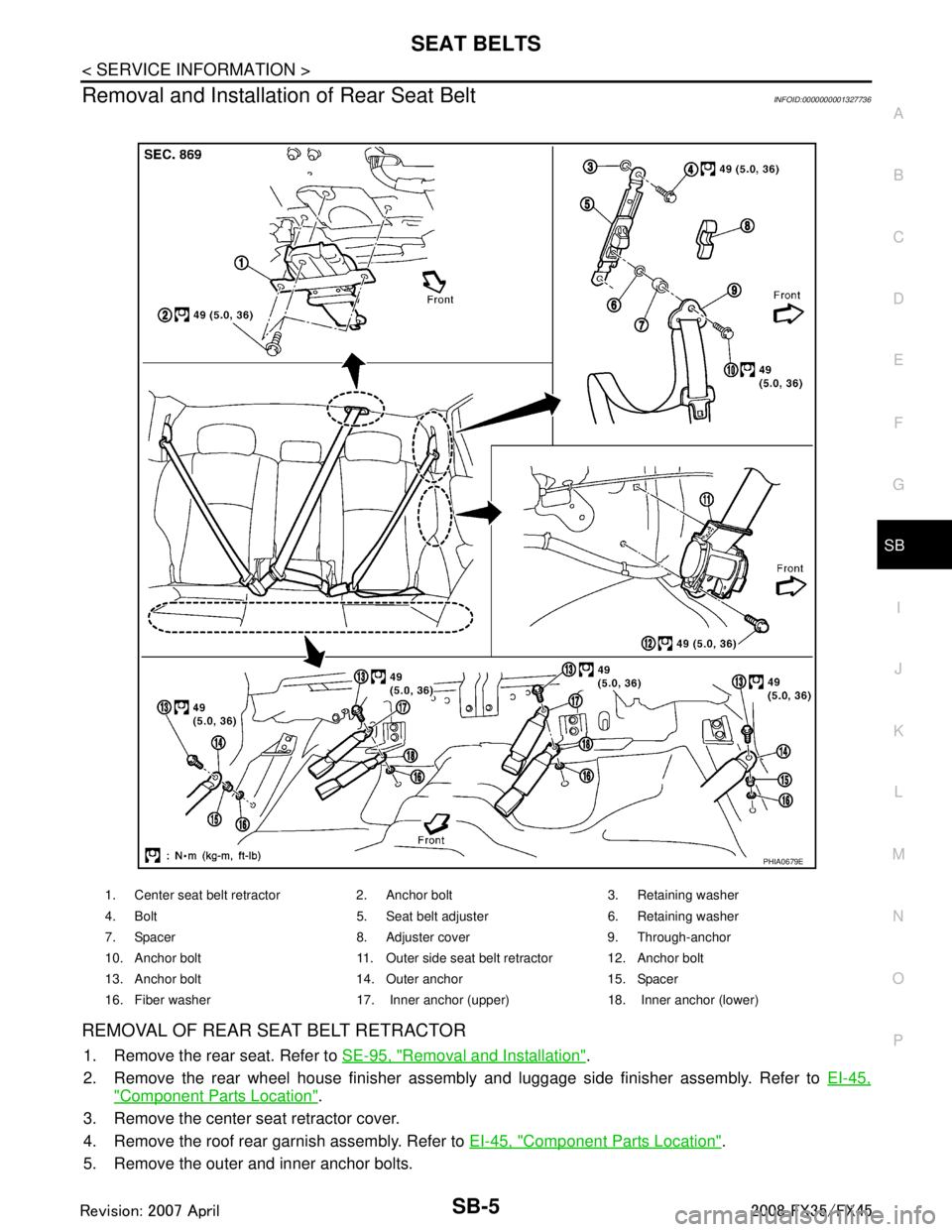
REMOVAL OF REAR SEAT BELT RETRACTOR
1. Remove the rear seat. Refer to SE-95, "Removal and Installation".
2. Remove the rear wheel house finisher assembly and luggage side finisher assembly. Refer to EI-45,
"Component Parts Location".
3. Remove the center seat retractor cover.
4. Remove the roof rear garnish assembly. Refer to EI-45, "
Component Parts Location".
5. Remove the outer and inner anchor bolts.
1. Center seat belt retractor 2. Anchor bolt 3. Retaining washer
4. Bolt 5. Seat belt adjuster 6. Retaining washer
7. Spacer 8. Adjuster cover 9. Through-anchor
10. Anchor bolt 11. Outer side seat belt retractor 12. Anchor bolt
13. Anchor bolt 14. Outer anchor 15. Spacer
16. Fiber washer 17. Inner anchor (upper) 18. Inner anchor (lower)
PHIA0679E
3AA93ABC3ACD3AC03ACA3AC03AC63AC53A913A773A893A873A873A8E3A773A983AC73AC93AC03AC3
3A893A873A873A8F3A773A9D3AAF3A8A3A8C3A863A9D3AAF3A8B3A8C
Page 3605 of 3924
SB-6
< SERVICE INFORMATION >
SEAT BELTS
6. Remove the outer side retractor and center seat retractor mounting anchor bolts.
7. Remove the seat belt assembly.
INSTALLATION OF REAR SEAT BELT RETRACTOR
Install in the reverse order of removal.
Seat Belt InspectionINFOID:0000000001327737
AFTER A COLLISION
WARNING:
Inspect all seat belt assemblies in cluding retractors and attaching hardware after any collision.
NISSAN recommends that all seat belt assemblies in use during a collision be replaced unless the col-
lision was minor and the belts show no damage and continue to operate properly. Failure to do so
could result in serious personal injury in an acci dent. Seat belt assemblies not in use during a colli-
sion should also be replaced if ei ther damage or improper operation is noted. Seat belt pre-tensioners
should be replaced even if the seat belts are not in use during a frontal collision in which the air bags
are deployed.
Replace any seat belt assembly (including anchor bolts) if:
The seat belt was in use at the time of a collision (except for minor collisions and the belts, retractors and
buckles show no damage and continue to operate properly).
The seat belt was damaged in an accident. (i.e. torn webbing, bent retractor or guide).
The seat belt attaching point was damaged in an acci dent. Inspect the seat belt attaching area for damage
or distortion and repair as necessary before installing a new seat belt assembly.
Anchor bolts are deformed or worn out.
The front seat belt pre-tensioner should be replaced even if the seat belts are not in use during the collision
in which the air bags are deployed.
PRELIMINARY CHECK
1. Check the seat belt warning lamp/chime for proper operation as follows:
a. Turn ignition switch ON. The seat belt warning lamp should illuminate. Also, the seat belt warning chime should sound for about six seconds.
b. Fasten driver's seat belt. The seat belt warni ng lamp should go out and the chime (if sounding) should
stop.
2. If the air bag warning lamp is blinking, perform self-diagnosis using CONSULT-II, and air bag warning lamp. Refer to SRS-23, "
SRS Operation Check".
3. Make sure that the seat belt retractor, seat belt anchor and buckle bolts are securely attached.
4. Check the shoulder seat belt guide and shoulder belt height adjuster for\
front seats. Ensure guide swivels freely and that webbing lays flat and does not bind in guide. Ensure height adjuster operates properly and
holds securely.
5. Check retractor operation:
a. Fully extend the seat belt webbing and c heck for twists, tears or other damage.
b. Allow the seat belt to retract. Ensure that webbing returns smoothly and completely into the retractor. If
the seat belt does not return smoothly, wipe the insi de of the loops with a clean paper cloth, because dirt
built up in the loops of the upper anchors can cause the seat belts to retract slowly.
c. Fasten the seat belt. Check the seat belt returns sm oothly and completely to the retractor. If the webbing
does not return smoothly, the cause may be an accumulation of dust or dirt. Use the “SEAT BELT TAPE
SET” and perform the following steps.
Inspect the front seat belt through-anchor:
1. Pull the seat belt out to a length of 500 mm (19.69 in) or more.
2. Use a clip or other device to the fix the seat belt at the center pillar webbing opening.
3. Pass a thin wire through the through-anchor webbing opening. Hold both ends of the wire and pull taut while moving it up and down several times along the webbing opening surface to remove dirt.
4. Any dirt that cannot be removed with the wir e can be removed by cleaning the opening with a clean
cloth.
5. Apply tape at the point where the webbi ng contacts the through-anchor webbing opening.
NOTE:
Apply the tape so that there is no looseness or wrinkling.
6. Remove the clip fixing the seat belt and ensure that the webbing returns smoothly.
3AA93ABC3ACD3AC03ACA3AC03AC63AC53A913A773A893A873A873A8E3A773A983AC73AC93AC03AC3
3A893A873A873A8F3A773A9D3AAF3A8A3A8C3A863A9D3AAF3A8B3A8C
Page 3608 of 3924
LATCH (LOWER ANCHORS AND TETHER FOR CHILDREN) SYSTEMSB-9
< SERVICE INFORMATION >
C
DE
F
G
I
J
K L
M A
B
SB
N
O P
LATCH (LOWER ANCHORS AND TETHER FOR CHILDREN) SYSTEM
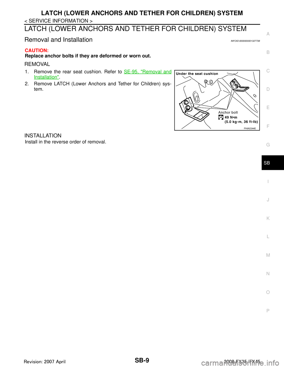
Removal and InstallationINFOID:0000000001327738
CAUTION:
Replace anchor bolts if they are deformed or worn out.
REMOVAL
1. Remove the rear seat cushion. Refer to SE-95, "Removal and
Installation".
2. Remove LATCH (Lower Anchors and Tether for Children) sys- tem.
INSTALLATION
Install in the reverse order of removal.
PHIA0344E
3AA93ABC3ACD3AC03ACA3AC03AC63AC53A913A773A893A873A873A8E3A773A983AC73AC93AC03AC3
3A893A873A873A8F3A773A9D3AAF3A8A3A8C3A863A9D3AAF3A8B3A8C
Page 3609 of 3924
SB-10
< SERVICE INFORMATION >
TOP TETHER STRAP CHILD RESTRAINT
TOP TETHER STRAP CHILD RESTRAINT
Removal and InstallationINFOID:0000000001327739
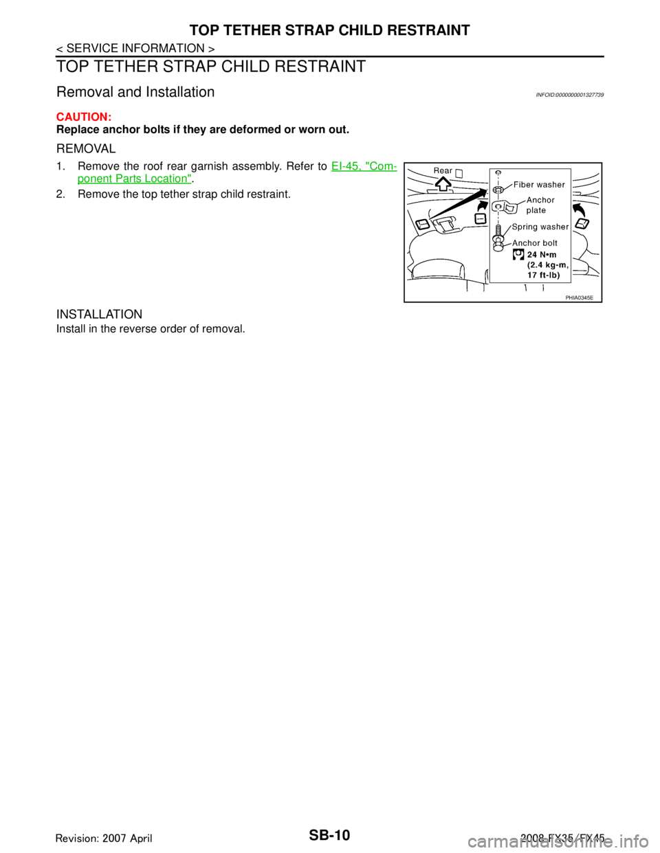
CAUTION:
Replace anchor bolts if they are deformed or worn out.
REMOVAL
1. Remove the roof rear garnish assembly. Refer to EI-45, "Com-
ponent Parts Location".
2. Remove the top tether strap child restraint.
INSTALLATION
Install in the reverse order of removal.
PHIA0345E
3AA93ABC3ACD3AC03ACA3AC03AC63AC53A913A773A893A873A873A8E3A773A983AC73AC93AC03AC3
3A893A873A873A8F3A773A9D3AAF3A8A3A8C3A863A9D3AAF3A8B3A8C
Page 3610 of 3924
SC-1
ELECTRICAL
C
DE
F
G H
I
J
L
M
SECTION SC
A
B
SC
N
O P
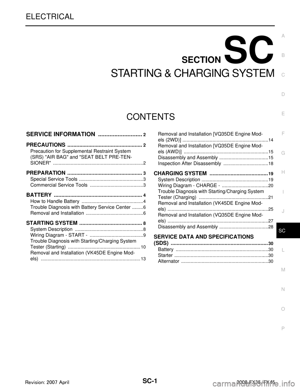
CONTENTS
STARTING & CHARGING SYSTEM
SERVICE INFORMATION .. ..........................2
PRECAUTIONS .............................................. .....2
Precaution for Supplemental Restraint System
(SRS) "AIR BAG" and "SEAT BELT PRE-TEN-
SIONER" ............................................................. ......
2
PREPARATION ...................................................3
Special Service Tools .......................................... ......3
Commercial Service Tools ........................................3
BATTERY ............................................................4
How to Handle Battery ........................................ ......4
Trouble Diagnosis with Battery Service Center .........6
Removal and Installation ...........................................6
STARTING SYSTEM ...........................................8
System Description ............................................. ......8
Wiring Diagram - START - ........................................9
Trouble Diagnosis with Starting/Charging System
Tester (Starting) ......................................................
10
Removal and Installation (VK45DE Engine Mod-
els) ..........................................................................
13
Removal and Installation [VQ35DE Engine Mod-
els (2WD)] ............................................................ ....
14
Removal and Installation [VQ35DE Engine Mod-
els (AWD)] ...............................................................
15
Disassembly and Assembly .....................................15
Inspection After Disassembly ..................................18
CHARGING SYSTEM .......................................19
System Description ..................................................19
Wiring Diagram - CHARGE - ...................................20
Trouble Diagnosis with Starting/Charging System
Tester (Charging) ....................................................
21
Removal and Installation (VK45DE Engine Mod-
els) ...........................................................................
25
Removal and Installation (VQ35DE Engine Mod-
els) ...........................................................................
27
Disassembly and Assembly .....................................28
SERVICE DATA AND SPECIFICATIONS
(SDS) .................................................................
30
Battery .....................................................................30
Starter ......................................................................30
Alternator .................................................................30
3AA93ABC3ACD3AC03ACA3AC03AC63AC53A913A773A893A873A873A8E3A773A983AC73AC93AC03AC3
3A893A873A873A8F3A773A9D3AAF3A8A3A8C3A863A9D3AAF3A8B3A8C
Page 3611 of 3924
SC-2
< SERVICE INFORMATION >
PRECAUTIONS
SERVICE INFORMATION
PRECAUTIONS
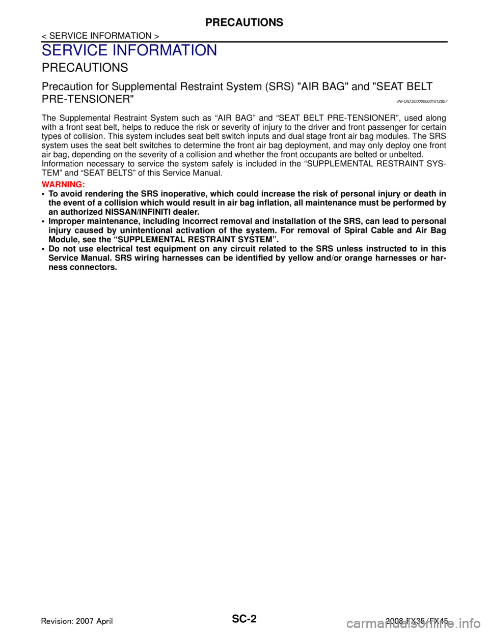
Precaution for Supplemental Restraint System (SRS) "AIR BAG" and "SEAT BELT
PRE-TENSIONER"
INFOID:0000000001612927
The Supplemental Restraint System such as “A IR BAG” and “SEAT BELT PRE-TENSIONER”, used along
with a front seat belt, helps to reduce the risk or severi ty of injury to the driver and front passenger for certain
types of collision. This system includes seat belt switch inputs and dual stage front air bag modules. The SRS
system uses the seat belt switches to determine the front air bag deployment, and may only deploy one front
air bag, depending on the severity of a collision and w hether the front occupants are belted or unbelted.
Information necessary to service the system safely is included in the “SUPPLEMENTAL RESTRAINT SYS-
TEM” and “SEAT BELTS” of this Service Manual.
WARNING:
• To avoid rendering the SRS inopera tive, which could increase the risk of personal injury or death in
the event of a collision which would result in air bag inflation, all maintenance must be performed by
an authorized NISS AN/INFINITI dealer.
Improper maintenance, including in correct removal and installation of the SRS, can lead to personal
injury caused by unintent ional activation of the system. For re moval of Spiral Cable and Air Bag
Module, see the “SUPPLEMEN TAL RESTRAINT SYSTEM”.
Do not use electrical test equipmen t on any circuit related to the SRS unless instructed to in this
Service Manual. SRS wiring harnesses can be identi fied by yellow and/or orange harnesses or har-
ness connectors.
3AA93ABC3ACD3AC03ACA3AC03AC63AC53A913A773A893A873A873A8E3A773A983AC73AC93AC03AC3
3A893A873A873A8F3A773A9D3AAF3A8A3A8C3A863A9D3AAF3A8B3A8C
Page 3615 of 3924
SC-6
< SERVICE INFORMATION >
BATTERY
CHARGING THE BATTERY
CAUTION:
Never “quick charge” a fully discharged battery.
Keep the battery away from open flame while it is being charged.
When connecting the charger, connect the leads first, then turn on the charger. Never turn on the
charger first, as this may cause a spark.
If battery electrolyte temperature rises above 55 °C (131 °F), stop charging. Always charge battery at a
temperature below 55 °C (131 °F).
Charging Rates
Never charge at more than 50 ampere rate.
NOTE:
The ammeter reading on your battery charger will automat ically decrease as the battery charges. This indi-
cates that the voltage of the battery is increasing norma lly as the state of charge improves. The charging amps
indicated above refer to initial charge rate.
If, after charging, the specific gravity of any two ce lls varies more than 0.050, the battery should be replaced.
Trouble Diagnosis with Battery Service CenterINFOID:0000000001328244
For battery testing, use Battery Service Center (J-48087) . For details and operating instructions, refer to Tech-
nical Service Bulletin and/or Battery Service Center User Guide.
Removal and InstallationINFOID:0000000001328245
REMOVAL
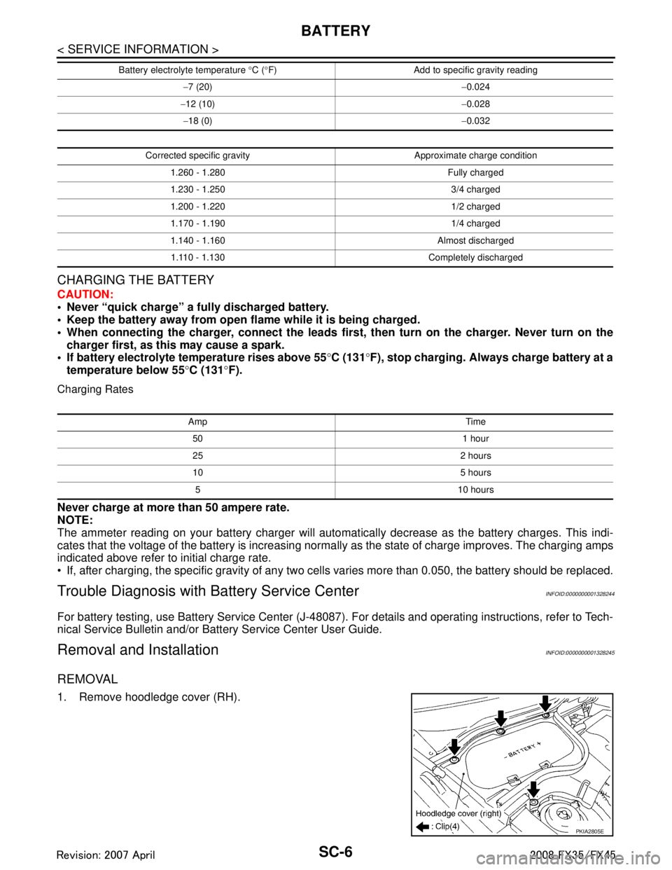
1. Remove hoodledge cover (RH).
− 7 (20) −0.024
− 12 (10) −0.028
− 18 (0) −0.032
Corrected specific gravity Approximate charge condition 1.260 - 1.280 Fully charged
1.230 - 1.250 3/4 charged
1.200 - 1.220 1/2 charged
1.170 - 1.190 1/4 charged
1.140 - 1.160 Almost discharged1.110 - 1.130 Completely discharged
Battery electrolyte temperature
°C ( °F) Add to specific gravity reading
Amp Time
50 1 hour
25 2 hours
10 5 hours5 10 hours
PKIA2805E
3AA93ABC3ACD3AC03ACA3AC03AC63AC53A913A773A893A873A873A8E3A773A983AC73AC93AC03AC3
3A893A873A873A8F3A773A9D3AAF3A8A3A8C3A863A9D3AAF3A8B3A8C
Page 3616 of 3924
BATTERYSC-7
< SERVICE INFORMATION >
C
DE
F
G H
I
J
L
M A
B
SC
N
O P
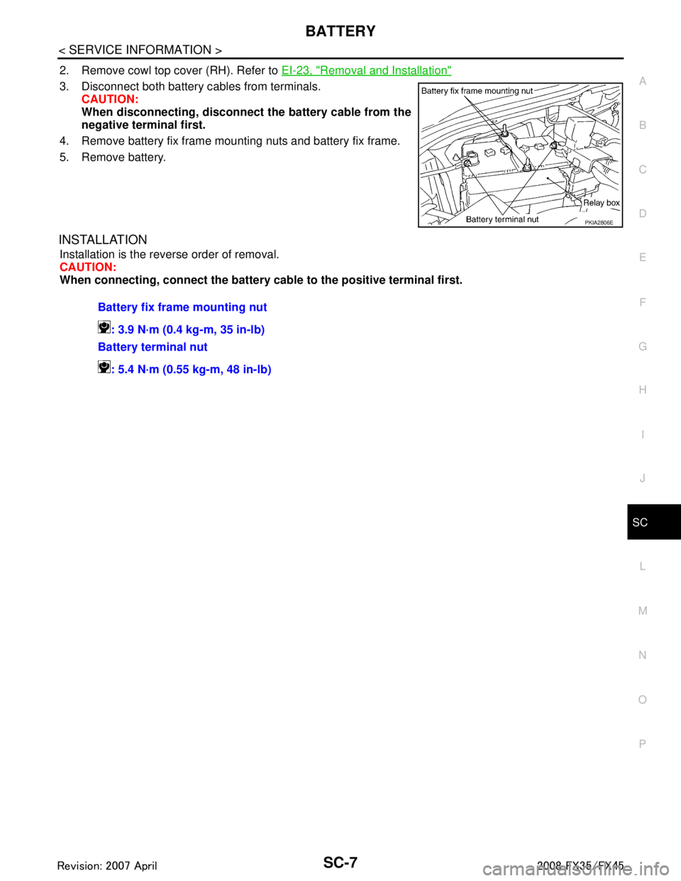
2. Remove cowl top cover (RH). Refer to EI-23, "Removal and Installation"
3. Disconnect both battery c ables from terminals.
CAUTION:
When disconnecting, disconnect the battery cable from the
negative terminal first.
4. Remove battery fix frame mounting nuts and battery fix frame.
5. Remove battery.
INSTALLATION
Installation is the reverse order of removal.
CAUTION:
When connecting, connect the battery cable to the positive terminal first.
PKIA2806E
Battery fix frame mounting nut
: 3.9 N·m (0.4 kg-m, 35 in-lb)
Battery terminal nut
: 5.4 N·m (0.55 kg-m, 48 in-lb)
3AA93ABC3ACD3AC03ACA3AC03AC63AC53A913A773A893A873A873A8E3A773A983AC73AC93AC03AC3
3A893A873A873A8F3A773A9D3AAF3A8A3A8C3A863A9D3AAF3A8B3A8C