Page 3558 of 3924
RFD-16
< SERVICE INFORMATION >
REAR FINAL DRIVE ASSEMBLY
REAR FINAL DRIVE ASSEMBLY
Removal and InstallationINFOID:0000000001327499
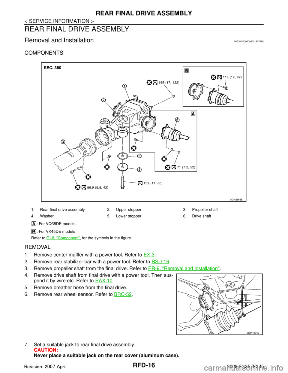
COMPONENTS
REMOVAL
1. Remove center muffler with a power tool. Refer to EX-3.
2. Remove rear stabilizer bar with a power tool. Refer to RSU-16
.
3. Remove propeller shaft from the final drive. Refer to PR-9, "
Removal and Installation".
4. Remove drive shaft from final drive with a power tool. Then sus- pend it by wire etc. Refer to RAX-10
.
5. Remove breather hose from the final drive.
6. Remove rear wheel sensor. Refer to BRC-52
.
7. Set a suitable jack to rear final drive assembly. CAUTION:
Never place a suitable jack on the rear cover (aluminum case).
1. Rear final drive assembly 2. Upper stopper 3. Propeller shaft
4. Washer 5. Lower stopper 6. Drive shaft
: For VQ35DE models
: For VK45DE models
Refer to GI-8, "
Component", for the symbols in the figure.
SDIA3563E
SDIA1094E
3AA93ABC3ACD3AC03ACA3AC03AC63AC53A913A773A893A873A873A8E3A773A983AC73AC93AC03AC3
3A893A873A873A8F3A773A9D3AAF3A8A3A8C3A863A9D3AAF3A8B3A8C
Page 3559 of 3924
REAR FINAL DRIVE ASSEMBLYRFD-17
< SERVICE INFORMATION >
CEF
G H
I
J
K L
M A
B
RFD
N
O P
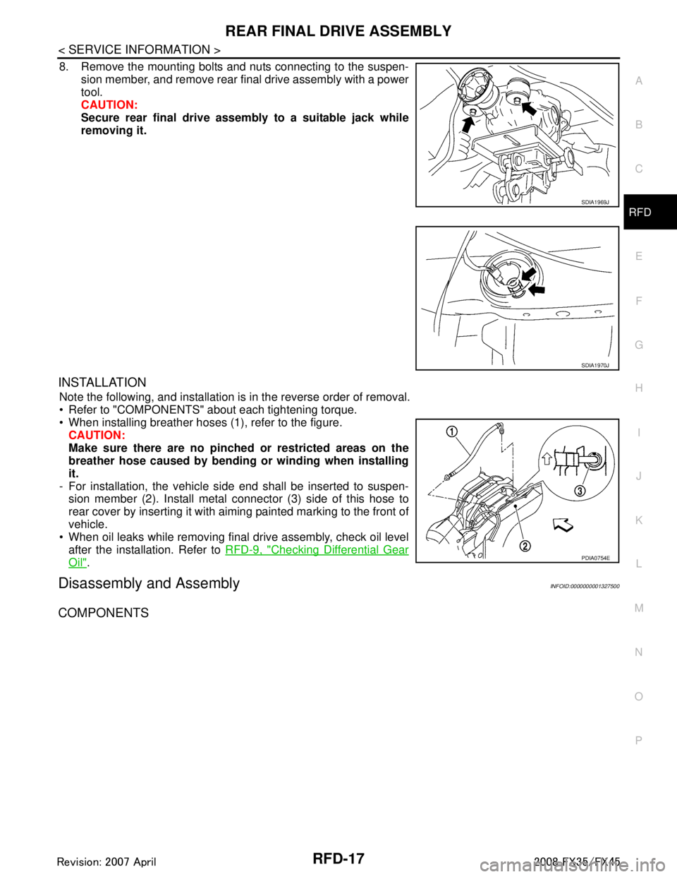
8. Remove the mounting bolts and nuts connecting to the suspen- sion member, and remove rear final drive assembly with a power
tool.
CAUTION:
Secure rear final drive assembly to a suitable jack while
removing it.
INSTALLATION
Note the following, and installation is in the reverse order of removal.
Refer to "COMPONENTS" about each tightening torque.
When installing breather hoses (1), refer to the figure.CAUTION:
Make sure there are no pinched or restricted areas on the
breather hose caused by bending or winding when installing
it.
- For installation, the vehicle side end shall be inserted to suspen- sion member (2). Install metal connector (3) side of this hose to
rear cover by inserting it with aiming painted marking to the front of
vehicle.
When oil leaks while removing final drive assembly, check oil level
after the installation. Refer to RFD-9, "
Checking Differential Gear
Oil".
Disassembly and AssemblyINFOID:0000000001327500
COMPONENTS
SDIA1969J
SDIA1970J
PDIA0754E
3AA93ABC3ACD3AC03ACA3AC03AC63AC53A913A773A893A873A873A8E3A773A983AC73AC93AC03AC3
3A893A873A873A8F3A773A9D3AAF3A8A3A8C3A863A9D3AAF3A8B3A8C
Page 3565 of 3924
REAR FINAL DRIVE ASSEMBLYRFD-23
< SERVICE INFORMATION >
CEF
G H
I
J
K L
M A
B
RFD
N
O P
6. For proper reinstallation, paint matching marks on one side of the bearing cap.
CAUTION:
For matching marks, use paint. Never damage bearingcaps and gear carrier.
Bearing caps are line-board during manufacture. The
matching marks are used to re install them in their original
positions.
7. Remove bearing caps.
8. Lift differential case assembly out with a suitable tool.
Keep side bearing outer races together with inner race. Do notmix them up.
Also, keep side bearing adjusting washers together with bear-
ings.
SDIA1795E
S-PD343
PDIA0547E
SPD527
3AA93ABC3ACD3AC03ACA3AC03AC63AC53A913A773A893A873A873A8E3A773A983AC73AC93AC03AC3
3A893A873A873A8F3A773A9D3AAF3A8A3A8C3A863A9D3AAF3A8B3A8C
Page 3566 of 3924
RFD-24
< SERVICE INFORMATION >
REAR FINAL DRIVE ASSEMBLY
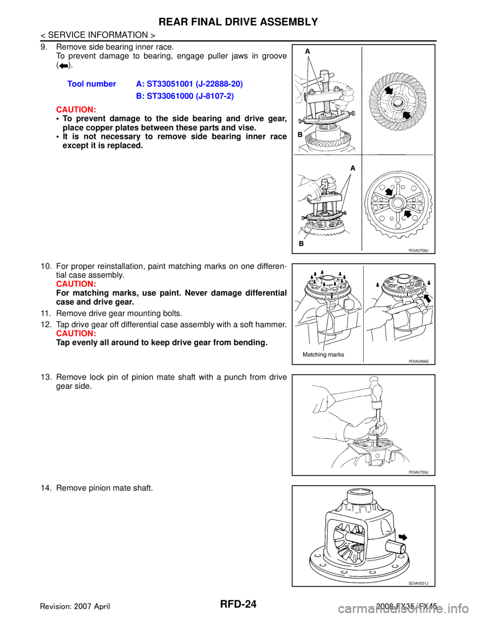
9. Remove side bearing inner race.To prevent damage to bearing, engage puller jaws in groove
().
CAUTION:
To prevent damage to the side bearing and drive gear,
place copper plates between these parts and vise.
It is not necessary to remove side bearing inner race
except it is replaced.
10. For proper reinstallation, paint matching marks on one differen- tial case assembly.
CAUTION:
For matching marks, use pain t. Never damage differential
case and drive gear.
11. Remove drive gear mounting bolts.
12. Tap drive gear off differential case assembly with a soft hammer. CAUTION:
Tap evenly all around to keep drive gear from bending.
13. Remove lock pin of pinion mate shaft with a punch from drive gear side.
14. Remove pinion mate shaft. Tool number A: ST33051001 (J-22888-20)
B: ST33061000 (J-8107-2)
PDIA0758J
PDIA0496E
PDIA0759J
SDIA0031J
3AA93ABC3ACD3AC03ACA3AC03AC63AC53A913A773A893A873A873A8E3A773A983AC73AC93AC03AC3
3A893A873A873A8F3A773A9D3AAF3A8A3A8C3A863A9D3AAF3A8B3A8C
Page 3567 of 3924
REAR FINAL DRIVE ASSEMBLYRFD-25
< SERVICE INFORMATION >
CEF
G H
I
J
K L
M A
B
RFD
N
O P
15. Turn pinion mate gear, then remove pinion mate gear, pinion mate thrust washer, side gear and side gear thrust washer from
differential case.
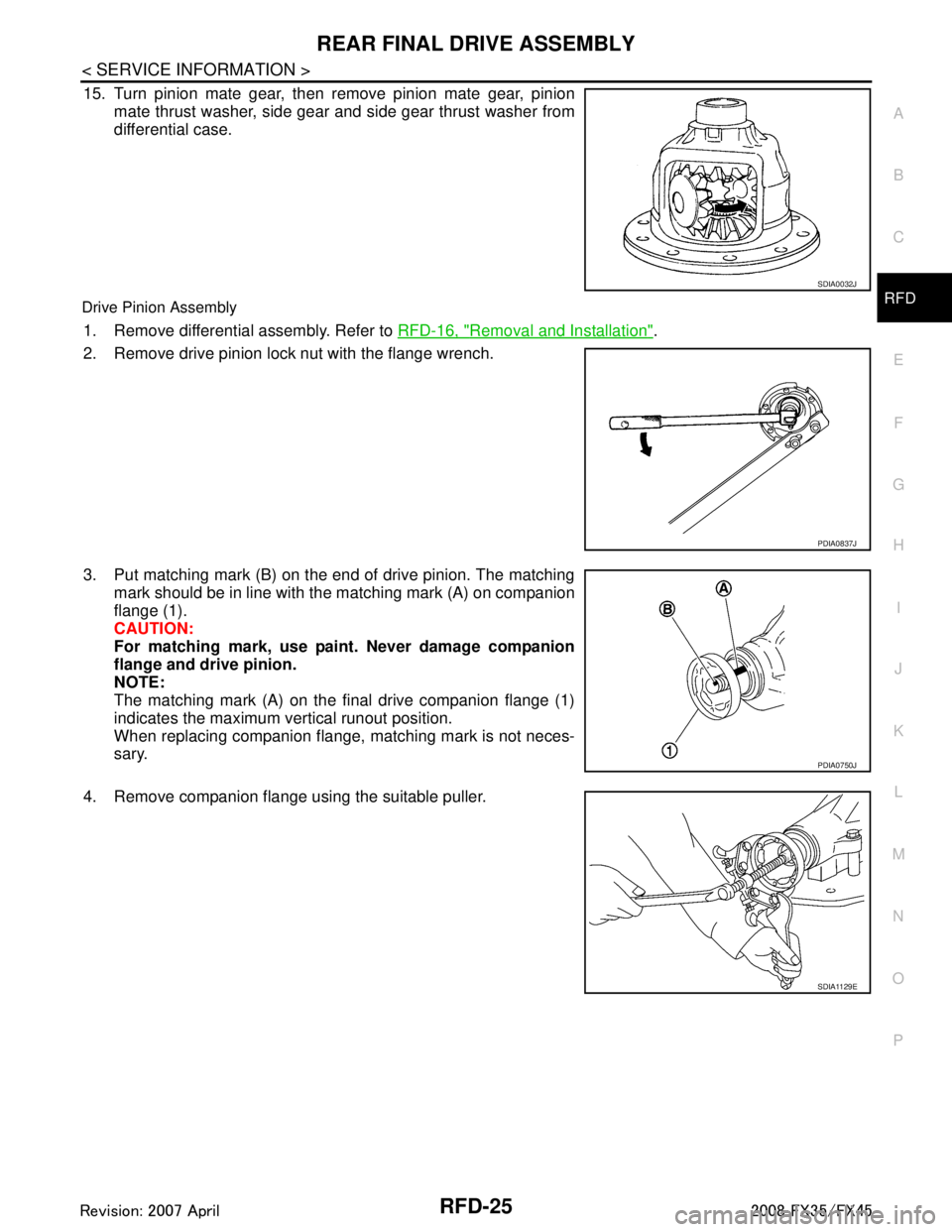
Drive Pinion Assembly
1. Remove differential assembly. Refer to RFD-16, "Removal and Installation".
2. Remove drive pinion lock nut with the flange wrench.
3. Put matching mark (B) on the end of drive pinion. The matching mark should be in line with the matching mark (A) on companion
flange (1).
CAUTION:
For matching mark, use pain t. Never damage companion
flange and drive pinion.
NOTE:
The matching mark (A) on the final drive companion flange (1)
indicates the maximum vertical runout position.
When replacing companion flange, matching mark is not neces-
sary.
4. Remove companion flange using the suitable puller.
SDIA0032J
PDIA0837J
PDIA0750J
SDIA1129E
3AA93ABC3ACD3AC03ACA3AC03AC63AC53A913A773A893A873A873A8E3A773A983AC73AC93AC03AC3
3A893A873A873A8F3A773A9D3AAF3A8A3A8C3A863A9D3AAF3A8B3A8C
Page 3571 of 3924
REAR FINAL DRIVE ASSEMBLYRFD-29
< SERVICE INFORMATION >
CEF
G H
I
J
K L
M A
B
RFD
N
O P
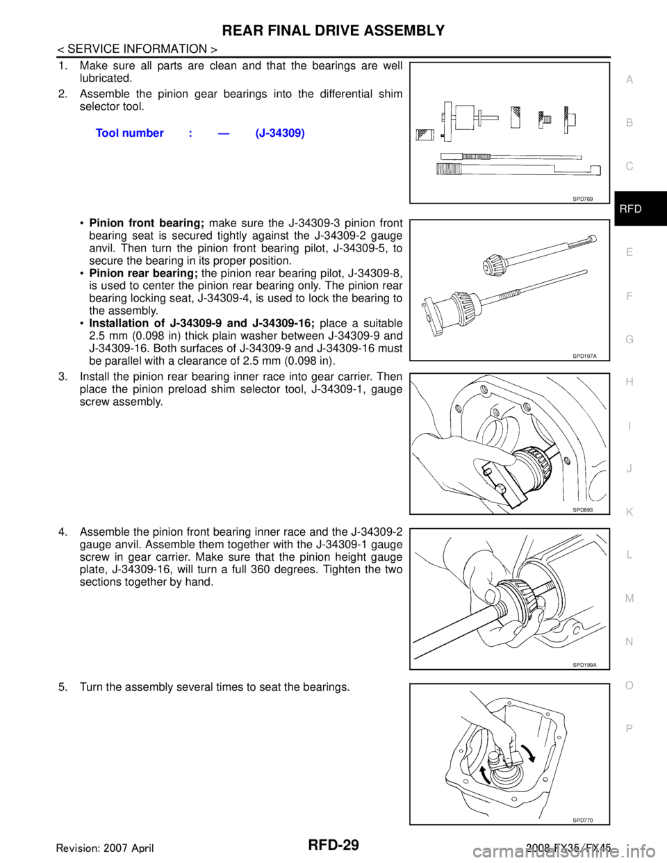
1. Make sure all parts are clean and that the bearings are well lubricated.
2. Assemble the pinion gear beari ngs into the differential shim
selector tool.
Pinion front bearing; make sure the J-34309-3 pinion front
bearing seat is secured tightly against the J-34309-2 gauge
anvil. Then turn the pinion front bearing pilot, J-34309-5, to
secure the bearing in its proper position.
Pinion rear bearing; the pinion rear bearing pilot, J-34309-8,
is used to center the pinion rear bearing only. The pinion rear
bearing locking seat, J-34309-4, is used to lock the bearing to
the assembly.
Installation of J-34309-9 and J-34309-16; place a suitable
2.5 mm (0.098 in) thick plain washer between J-34309-9 and
J-34309-16. Both surfaces of J-34309-9 and J-34309-16 must
be parallel with a clearance of 2.5 mm (0.098 in).
3. Install the pinion rear bearing inner race into gear carrier. Then place the pinion preload shim selector tool, J-34309-1, gauge
screw assembly.
4. Assemble the pinion front bearing inner race and the J-34309-2 gauge anvil. Assemble them together with the J-34309-1 gauge
screw in gear carrier. Make sure that the pinion height gauge
plate, J-34309-16, will turn a full 360 degrees. Tighten the two
sections together by hand.
5. Turn the assembly several times to seat the bearings. Tool number : — (J-34309)
SPD769
SPD197A
SPD893
SPD199A
SPD770
3AA93ABC3ACD3AC03ACA3AC03AC63AC53A913A773A893A873A873A8E3A773A983AC73AC93AC03AC3
3A893A873A873A8F3A773A9D3AAF3A8A3A8C3A863A9D3AAF3A8B3A8C
Page 3579 of 3924
REAR FINAL DRIVE ASSEMBLYRFD-37
< SERVICE INFORMATION >
CEF
G H
I
J
K L
M A
B
RFD
N
O P
a. Attach the protector to side oil seal.
b. After the side flange is inserted and the serrated part of side gear has engaged the serrated part of flange, remove the pro-
tector.
c. Put a suitable drift on the center of side flange, then drive it until sound changes.
NOTE:
When installation is completed, driving sound of the side flange turns into a sound which seems to affect
the whole final drive.
d. Confirm that the dimension of the side flange installation (Mea- surement A) in the figure comes into the following.Tool number : KV38107900 (J-39352)
SDIA0822E
Measurement A: 326 - 328 mm (12.83 - 12.91 in)
SDIA1039E
3AA93ABC3ACD3AC03ACA3AC03AC63AC53A913A773A893A873A873A8E3A773A983AC73AC93AC03AC3
3A893A873A873A8F3A773A9D3AAF3A8A3A8C3A863A9D3AAF3A8B3A8C
Page 3582 of 3924
RSU-1
SUSPENSION
C
DF
G H
I
J
K L
M
SECTION RSU
A
B
RSU
N
O PCONTENTS
REAR SUSPENSION
SERVICE INFORMATION .. ..........................2
PRECAUTIONS .............................................. .....2
Cautions .............................................................. ......2
PREPARATION ...................................................3
Special Service Tool ........................................... ......3
Commercial Service Tool ..........................................3
NOISE, VIBRATION AND HARSHNESS
(NVH) TROUBLESHOOTING .............................
4
NVH Troubleshooting Chart ................................ ......4
REAR SUSPENSION ASSEMBLY .....................5
On-Vehicle Inspection and Service ..................... ......5
Wheel AlignmentInspection .......................................5
Removal and Installation ...........................................6
SHOCK ABSORBER ..........................................9
Removal and Installation ..................................... ......9
Disassembly and Assembly ......................................9
SUSPENSION ARM ..........................................11
Removal and Installation ..................................... ....11
RADIUS ROD ................................... .................13
Removal and Installation ..................................... ....13
FRONT LOWER LINK .......................................14
Removal and Installation .........................................14
REAR LOWER LINK & COIL SPRING .............15
Removal and Installation .........................................15
STABILIZER BAR .............................................16
Removal and Installation .........................................16
REAR SUSPENSION MEMBER .......................17
Removal and Installation ..................................... ....17
SERVICE DATA AND SPECIFICATIONS
(SDS) .................................................................
18
Wheel Alignment (Unladen*) ...................................18
Ball Joint ..................................................................18
Wheelarch Height (Unladen*) ..................................18
3AA93ABC3ACD3AC03ACA3AC03AC63AC53A913A773A893A873A873A8E3A773A983AC73AC93AC03AC3
3A893A873A873A8F3A773A9D3AAF3A8A3A8C3A863A9D3AAF3A8B3A8C