2008 INFINITI FX35 installation
[x] Cancel search: installationPage 3736 of 3924
REAR SEATSE-97
< SERVICE INFORMATION >
C
DE
F
G H
J
K L
M A
B
SE
N
O P
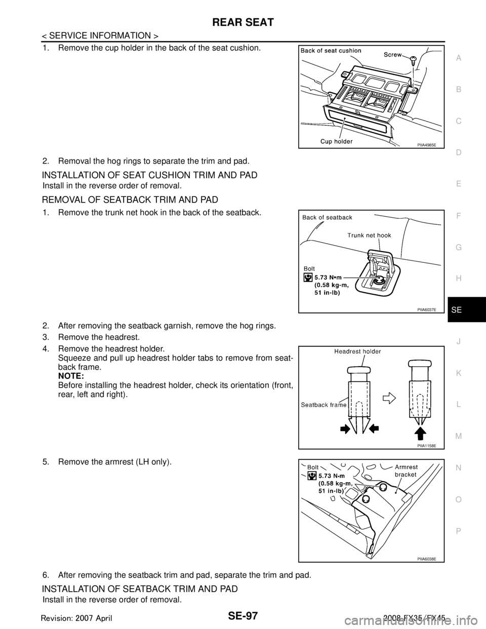
1. Remove the cup holder in the back of the seat cushion.
2. Removal the hog rings to separate the trim and pad.
INSTALLATION OF SEAT CUSHION TRIM AND PAD
Install in the reverse order of removal.
R E M O VA L O F S E AT B A C K T R I M A N D PA D
1. Remove the trunk net hook in the back of the seatback.
2. After removing the seatback garnish, remove the hog rings.
3. Remove the headrest.
4. Remove the headrest holder. Squeeze and pull up headrest holder tabs to remove from seat-
back frame.
NOTE:
Before installing the headrest holder, check its orientation (front,
rear, left and right).
5. Remove the armrest (LH only).
6. After removing the seatback trim and pad, separate the trim and pad.
INSTALLATION OF SEATBACK TRIM AND PAD
Install in the reverse order of removal.
PIIA4985E
PIIA6037E
PIIA1158E
PIIA6038E
3AA93ABC3ACD3AC03ACA3AC03AC63AC53A913A773A893A873A873A8E3A773A983AC73AC93AC03AC3
3A893A873A873A8F3A773A9D3AAF3A8A3A8C3A863A9D3AAF3A8B3A8C
Page 3737 of 3924
SE-98
< SERVICE INFORMATION >
REAR SEAT
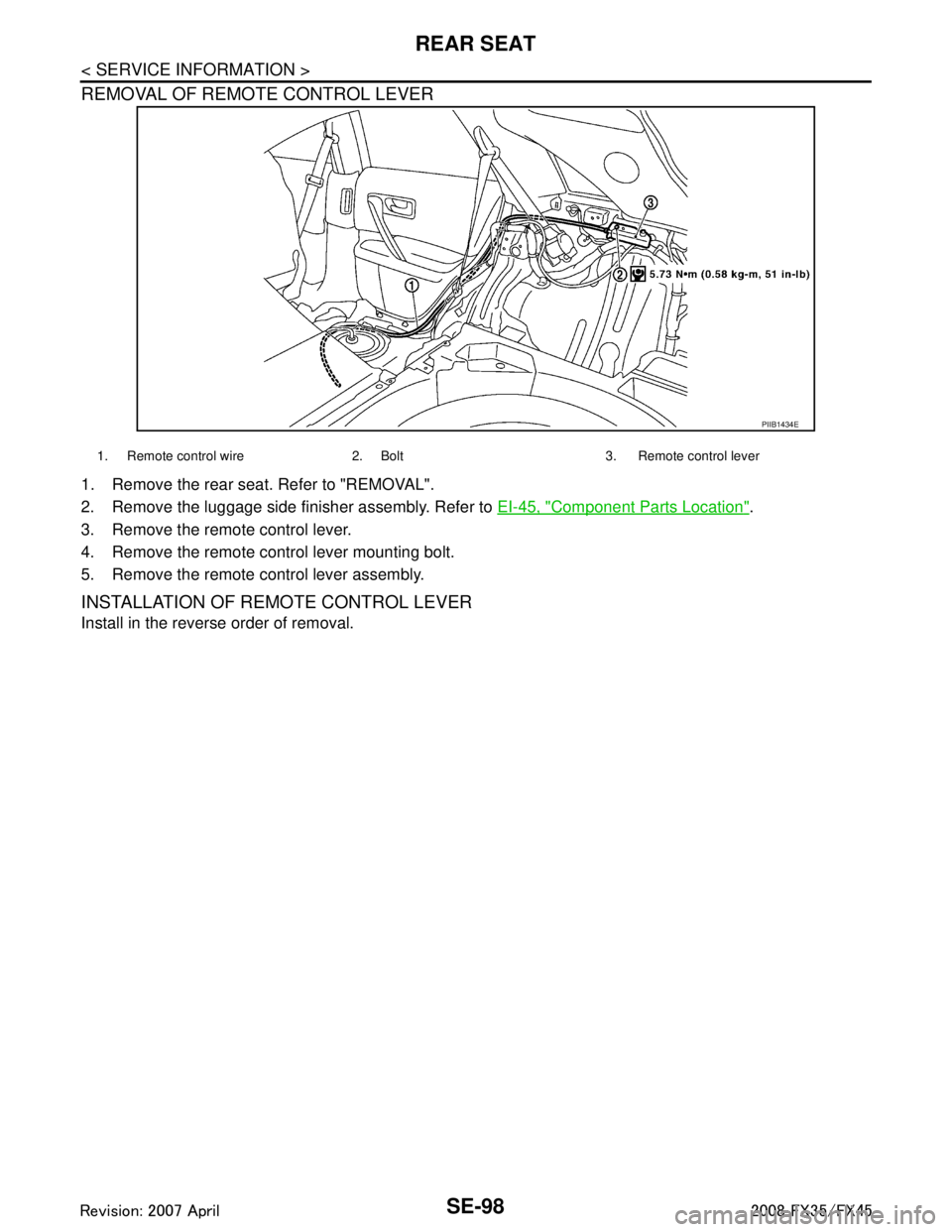
REMOVAL OF REMOTE CONTROL LEVER
1. Remove the rear seat. Refer to "REMOVAL".
2. Remove the luggage side finisher assembly. Refer to EI-45, "
Component Parts Location".
3. Remove the remote control lever.
4. Remove the remote control lever mounting bolt.
5. Remove the remote control lever assembly.
INSTALLATION OF REMOTE CONTROL LEVER
Install in the reverse order of removal.
PIIB1434E
1. Remote control wire 2. Bolt 3. Remote control lever
3AA93ABC3ACD3AC03ACA3AC03AC63AC53A913A773A893A873A873A8E3A773A983AC73AC93AC03AC3
3A893A873A873A8F3A773A9D3AAF3A8A3A8C3A863A9D3AAF3A8B3A8C
Page 3738 of 3924

SRS-1
RESTRAINTS
C
DE
F
G
I
J
K L
M
SECTION SRS
A
B
SRS
N
O P
CONTENTS
SUPPLEMENTAL RESTRAINT SYSTEM (SRS)
SERVICE INFORMATION .. ..........................2
DTC INDEX ..................................................... .....2
B1001-B1015 ...................................................... ......2
B1017-B1035 ............................................................2
B1042-B1057 ............................................................3
B1058-B1073 ............................................................3
B1074-B1089 ............................................................4
B1106-B1120 ............................................................4
B1122-B1137 ............................................................5
B1138-B1153 ............................................................5
B1202-B1210 ............................................................5
PRECAUTIONS ...................................................7
Precaution for Supplemental Restraint System
(SRS) "AIR BAG" and "SEAT BELT PRE-TEN-
SIONER" ............................................................. ......
7
Precaution for SRS "AIR BAG" and "SEAT BELT
PRE-TENSIONER" Service ......................................
7
Occupant Classification System Precaution .............7
PREPARATION ...................................................8
Commercial Service Tool .................................... ......8
SUPPLEMENTAL RESTRAINT SYSTEM
(SRS) ...................................................................
9
SRS Configuration .............................................. ......9
Front Seat Belt Pre-tensioner with Load Limiter .....10
Front Side Air Bag ...................................................10
Side Curtain Air Bag ................................................10
Occupant Classification System (OCS) ..................10
Passenger Air Bag Status Condition .......................11
Component Parts of Occupant Classification Sys-
tem ..........................................................................
11
TROUBLE DIAGNOSIS .....................................12
Trouble Diagnosis Introduction ........................... ....12
Component Parts Location ......................................14
Schematic ...............................................................15
Wiring Diagram - SRS - ...........................................16
CONSULT-III Function ........................................
....21
Self-Diagnosis Function (Without CONSULT-III) .....22
SRS Operation Check .............................................23
Trouble Diagnosis with CONSULT-III ......................24
Trouble Diagnosis without CONSULT-III .................28
Trouble Diagnosis: "AIR BAG" Warning Lamp
Does Not Turn OFF .................................................
32
Trouble Diagnosis: "AIR BAG" Warning Lamp
Does Not Turn ON ...................................................
32
DRIVER AIR BAG MODULE ............................34
Removal and Installation .........................................34
SPIRAL CABLE ................................................36
Removal and Installation .........................................36
FRONT PASSENGER AIR BAG MODULE ......38
Removal and Installation .........................................38
SIDE CURTAIN AIR BAG MODULE ................40
Removal and Installation .........................................40
CRASH ZONE SENSOR ...................................42
Removal and Installation ..................................... ....42
SIDE AIR BAG (SATELLITE) SENSOR ...........43
Removal and Installation .........................................43
DIAGNOSIS SENSOR UNIT .............................44
Removal and Installation .........................................44
FRONT SEAT BELT PRE-TENSIONER ...........45
Removal and Installation .........................................45
OCCUPANT CLASSIFICATION SYSTEM
CONTROL UNIT ................................................
46
Removal and Installation .........................................46
COLLISION DIAGNOSIS ..................................47
For Frontal Collision ................................................47
For Side Collision ....................................................48
3AA93ABC3ACD3AC03ACA3AC03AC63AC53A913A773A893A873A873A8E3A773A983AC73AC93AC03AC3
3A893A873A873A8F3A773A9D3AAF3A8A3A8C3A863A9D3AAF3A8B3A8C
Page 3744 of 3924
PRECAUTIONSSRS-7
< SERVICE INFORMATION >
C
DE
F
G
I
J
K L
M A
B
SRS
N
O P
PRECAUTIONS
Precaution for Supplemental Restraint System (SRS) "AIR BAG" and "SEAT BELT
PRE-TENSIONER"
INFOID:0000000001612877
The Supplemental Restraint System such as “A IR BAG” and “SEAT BELT PRE-TENSIONER”, used along
with a front seat belt, helps to reduce the risk or severi ty of injury to the driver and front passenger for certain
types of collision. This system includes seat belt switch inputs and dual stage front air bag modules. The SRS
system uses the seat belt switches to determine the front air bag deployment, and may only deploy one front
air bag, depending on the severity of a collision and whether the front occupants are belted or unbelted.
Information necessary to service the system safely is included in the “SUPPLEMENTAL RESTRAINT SYS-
TEM” and “SEAT BELTS” of this Service Manual.
WARNING:
• To avoid rendering the SRS inoper ative, which could increase the risk of personal injury or death in
the event of a collision which would result in air bag inflation, all maintenance must be performed by
an authorized NISSAN/INFINITI dealer.
Improper maintenance, including in correct removal and installation of the SRS, can lead to personal
injury caused by unintentional act ivation of the system. For removal of Spiral Cable and Air Bag
Module, see the “SUPPLEMEN TAL RESTRAINT SYSTEM”.
Do not use electrical test equipm ent on any circuit related to the SRS unless instructed to in this
Service Manual. SRS wiring harnesses can be identi fied by yellow and/or orange harnesses or har-
ness connectors.
Precaution for SRS "AIR BAG" and "SEAT BELT PRE-TENSIONER" Service
INFOID:0000000001327741
Do not use electrical test equipment to check SRS ci rcuits unless instructed to in this Service Manual.
Before servicing the SRS, turn ignition switch OFF, disconnect both battery cables and wait at least 3 min-
utes.
For approximately 3 minutes after the cables are remov ed, it is still possible for the air bag and seat belt pre-
tensioner to deploy. Therefore, do not work on any SR S connectors or wires until at least 3 minutes have
passed.
Diagnosis sensor unit must always be installed with their arrow marks “ ⇐” pointing towards the front of the
vehicle for proper operation. Also check diagnosis sensor unit for cracks, deformities or rust before installa-
tion and replace as required.
The spiral cable must be aligned with the neutral position since its rotations are limited. Do not turn steering
wheel and column after removal of steering gear.
Handle air bag module carefully. Always place driver and front passenger air bag modules with the pad side facing upward and seat mounted front side air bag module standing with the stud bolt side facing down.
Conduct self-diagnosis to check entire SRS for proper function after replacing any components.
After air bag inflates, the front instrument panel assembly should be replaced if damaged.
Always replace instrument panel pad following front passenger air bag deployment.
Disposal, recycling, and transportation of air bag m odules and seat belt pre-tensioners should be performed
in compliance with applicable federal, state and local laws and regulations.
Occupant Classification System PrecautionINFOID:0000000001327742
Replace occupant classification system control uni t and passenger front seat cushion as an assembly.
Refer to Refer to Service Manual .
3AA93ABC3ACD3AC03ACA3AC03AC63AC53A913A773A893A873A873A8E3A773A983AC73AC93AC03AC3
3A893A873A873A8F3A773A9D3AAF3A8A3A8C3A863A9D3AAF3A8B3A8C
Page 3759 of 3924
SRS-22
< SERVICE INFORMATION >
TROUBLE DIAGNOSIS
Diagnosis results previously stored in the memory are displayed on the CONSULT-III screen. The stored
results are not erased until memory erasing is executed.
“TROUBLE DIAG RECORD”
With TROUBLE DIAG RECORD, diagnosis results previ ously erased by a reset operation can be displayed
on the CONSULT-III screen.
“ECU DISCRIMINATED NO.”
The diagnosis sensor unit for each vehicle model is assigned with its own, individual classification number.
This number will be displayed on the CONSULT-III scr een, as shown. When replacing the diagnosis sensor
unit, refer to the part number for the compatibility. Af ter installation, replacement with a correct unit can be
checked by confirming this classification number on the CONSULT-III screen.
After repair, make sure the discriminated number of diagnosis sensor unit installed to vehicle are same.
Refer to SRS-44, "
Removal and Installation".
HOW TO CHANGE SELF-DIAGNOSIS MODE WITH CONSULT-III
From User Mode to Diagnosis Mode
After selecting “AIR BAG” on the “SELECT SYSTEM” screen, User mode automatically changes to Diagnosis
mode.
From Diagnosis Mode to User Mode
To return to User mode from Diagnosis mode, touch “BACK” key of CONSULT-III until “SELECT SYSTEM”
appears, then diagnosis mode automat ically changes to User mode.
HOW TO ERASE SELF-DIAGNOSTIC RESULTS
“SELF-DIAG [CURRENT]”
A current self-diagnostic result is displayed on the CONSULT-III screen in real time.
After the malfunction is repaired completely, no malfunction is detected on “SELF-DIAG [CURRENT]”.
“SELF-DIAG [PAST]” Return to the “SELF-DIAG [CURRENT]” CONSULT-III screen by touching “BACK” key of CONSULT-III and
select “SELF-DIAG [CURRENT]” in SELECT DIAG MODE. Touch “ERASE” in “SELF-DIAG [CURRENT]”
mode.
NOTE:
If the memory of the malfunction in “SELF-DIAG [P AST]” is not erased, the User mode shows the system
malfunction by the operation of the warning lamp even if the malfunction is repaired completely.
“TROUBLE DIAG RECORD”
The memory of “TROUBLE DI AG RECORD” cannot be erased.
Self-Diagnosis Function (Without CONSULT-III)INFOID:0000000001524166
The reading of these results is accomplished “User mode” and “Diagnosis mode”.
After a malfunction is repaired, turn ignition switch ON. Diagnosis mode returns to the User mode. At that
time, the self-diagnostic result is cleared.
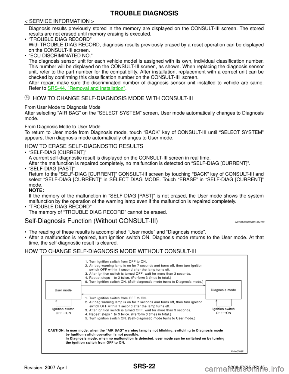
HOW TO CHANGE SELF-DIAGNOSIS MODE WITHOUT CONSULT-III
PHIA0709E
3AA93ABC3ACD3AC03ACA3AC03AC63AC53A913A773A893A873A873A8E3A773A983AC73AC93AC03AC3
3A893A873A873A8F3A773A9D3AAF3A8A3A8C3A863A9D3AAF3A8B3A8C
Page 3771 of 3924
SRS-34
< SERVICE INFORMATION >
DRIVER AIR BAG MODULE
DRIVER AIR BAG MODULE
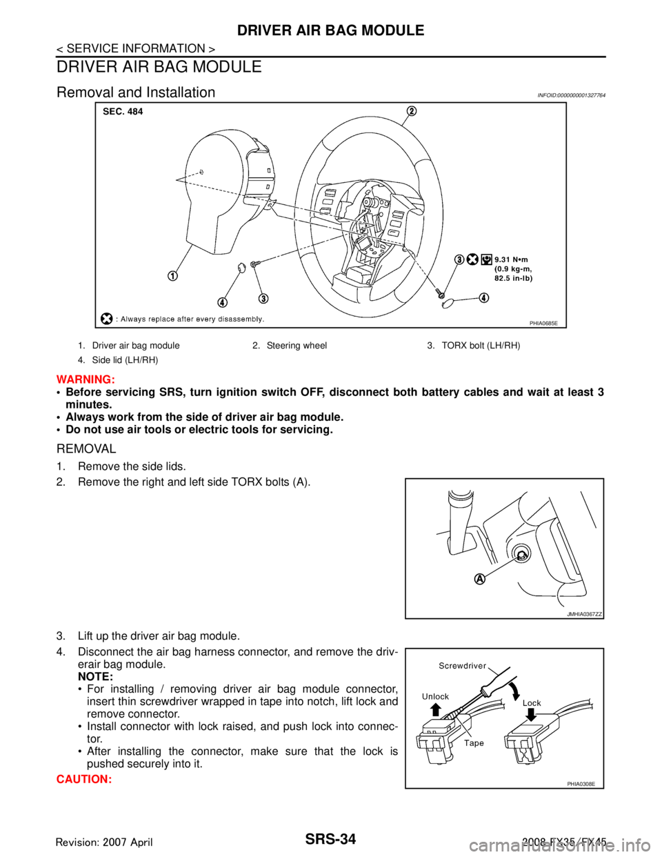
Removal and InstallationINFOID:0000000001327764
WARNING:
Before servicing SRS, turn ignition switch OFF, disconnect both ba ttery cables and wait at least 3
minutes.
Always work from the side of driver air bag module.
Do not use air tools or el ectric tools for servicing.
REMOVAL
1. Remove the side lids.
2. Remove the right and left side TORX bolts (A).
3. Lift up the driver air bag module.
4. Disconnect the air bag harness connector, and remove the driv-
erair bag module.
NOTE:
For installing / removing driver air bag module connector,insert thin screwdriver wrapped in tape into notch, lift lock and
remove connector.
Install connector with lock raised, and push lock into connec- tor.
After installing the connector, make sure that the lock is pushed securely into it.
CAUTION:
PHIA0685E
1. Driver air bag module 2. Steering wheel 3. TORX bolt (LH/RH)
4. Side lid (LH/RH)
JMHIA0367ZZ
PHIA0308E
3AA93ABC3ACD3AC03ACA3AC03AC63AC53A913A773A893A873A873A8E3A773A983AC73AC93AC03AC3
3A893A873A873A8F3A773A9D3AAF3A8A3A8C3A863A9D3AAF3A8B3A8C
Page 3772 of 3924
DRIVER AIR BAG MODULESRS-35
< SERVICE INFORMATION >
C
DE
F
G
I
J
K L
M A
B
SRS
N
O P
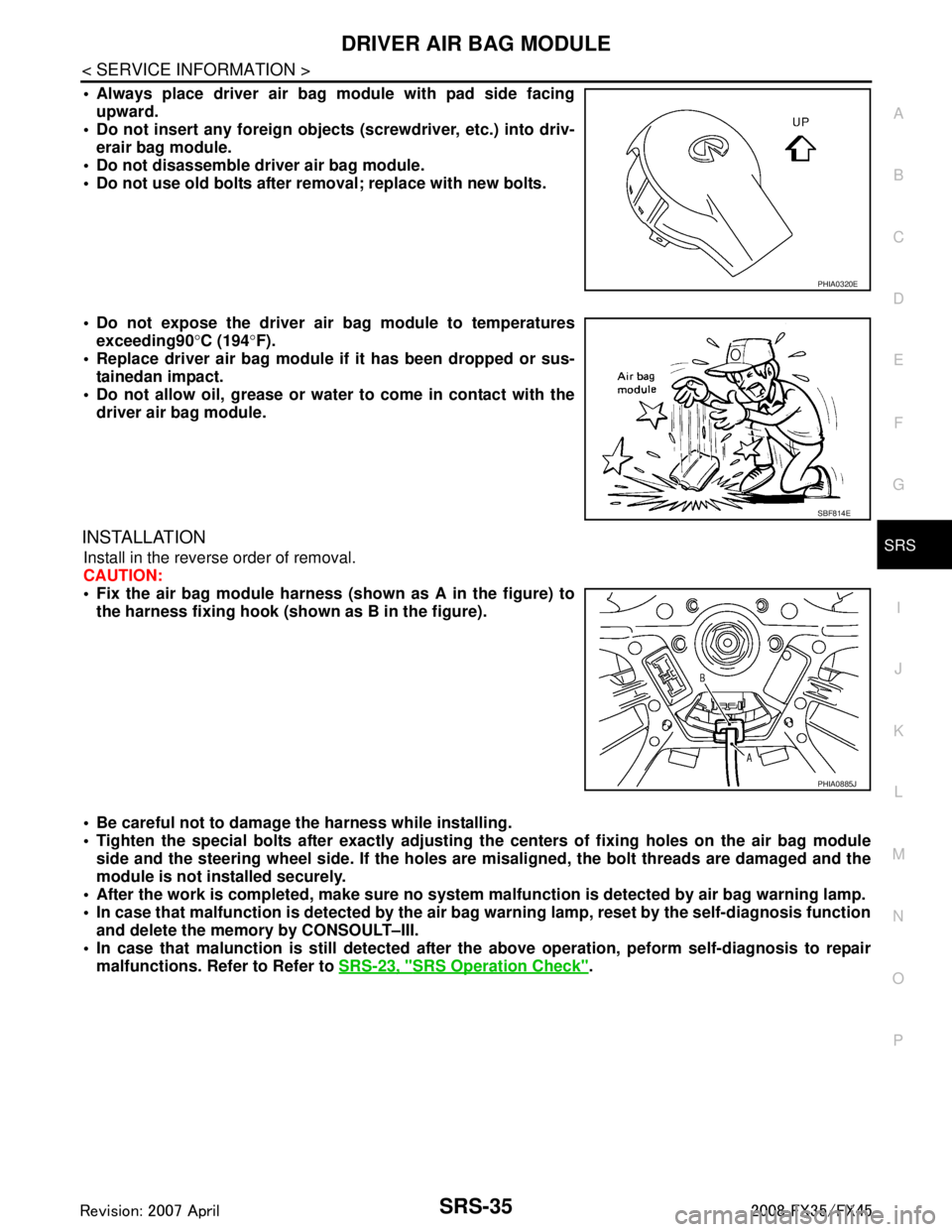
Always place driver air bag module with pad side facing upward.
Do not insert any foreign objects (screwdriver, etc.) into driv-
erair bag module.
Do not disassemble driver air bag module.
Do not use old bolts after removal; replace with new bolts.
Do not expose the driver air bag module to temperatures exceeding90 °C (194 °F).
Replace driver air bag module if it has been dropped or sus-
tainedan impact.
Do not allow oil, grease or water to come in contact with the
driver air bag module.
INSTALLATION
Install in the reverse order of removal.
CAUTION:
Fix the air bag module harness (shown as A in the figure) to
the harness fixing hook (s hown as B in the figure).
Be careful not to damage the harness while installing.
Tighten the special bolts after exactly adjusting the centers of fi xing holes on the air bag module
side and the steering wheel side. If the holes are misaligned, the bolt threads are damaged and the
module is not installed securely.
After the work is completed, make sure no system malfunction is detected by air bag warning lamp.
In case that malfunction is detected by the air ba g warning lamp, reset by the self-diagnosis function
and delete the memory by CONSOULT–III.
In case that malunction is still detected after th e above operation, peform self-diagnosis to repair
malfunctions. Refer to Refer to SRS-23, "
SRS Operation Check".
PHIA0320E
SBF814E
PHIA0885J
3AA93ABC3ACD3AC03ACA3AC03AC63AC53A913A773A893A873A873A8E3A773A983AC73AC93AC03AC3
3A893A873A873A8F3A773A9D3AAF3A8A3A8C3A863A9D3AAF3A8B3A8C
Page 3773 of 3924
SRS-36
< SERVICE INFORMATION >
SPIRAL CABLE
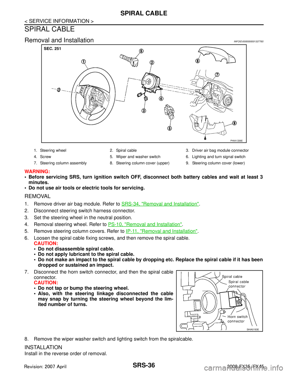
SPIRAL CABLE
Removal and InstallationINFOID:0000000001327765
WARNING:
Before servicing SRS, turn ignition switch OFF, disconnect both ba ttery cables and wait at least 3
minutes.
Do not use air tools or el ectric tools for servicing.
REMOVAL
1. Remove driver air bag module. Refer to SRS-34, "Removal and Installation".
2. Disconnect steering switch harness connector.
3. Set the steering wheel in the neutral position.
4. Removal steering wheel. Refer to PS-10, "
Removal and Installation".
5. Remove steering column covers. Refer to IP-11, "
Removal and Installation".
6. Loosen the spiral cable fixing screws, and then remove the spiral cable. CAUTION:
Do not disassemble spiral cable.
Do not apply lubricant to the spiral cable.
Do not make an impact to the spiral cable by dro pping etc. Replace the spiral cable if it has been
dropped or sustained an impact.
7. Disconnect the horn switch connec tor, and then the spiral cable
connector.
CAUTION:
Do not tap or bump the steering wheel.
Also, with the steering li nkage disconnected the cable
may snap by turning the st eering wheel beyond the lim-
ited number of turns.
8. Remove the wiper washer switch and lighting switch from the spiralcable.
INSTALLATION
Install in the reverse order of removal.
PHIA1336E
1. Steering wheel 2. Spiral cable 3. Driver air bag module connector
4. Screw 5. Wiper and washer switch 6. Lighting and turn signal switch
7. Steering column assembly 8. Steering column cover (upper) 9. Steering column cover (lower)
SHIA0193E
3AA93ABC3ACD3AC03ACA3AC03AC63AC53A913A773A893A873A873A8E3A773A983AC73AC93AC03AC3
3A893A873A873A8F3A773A9D3AAF3A8A3A8C3A863A9D3AAF3A8B3A8C