2008 INFINITI FX35 installation
[x] Cancel search: installationPage 3826 of 3924
TF-40
< SERVICE INFORMATION >
TRANSFER ASSEMBLY
TRANSFER ASSEMBLY
Removal and InstallationINFOID:0000000001327460
REMOVAL
1. Remove tunnel stay with power tool. Refer to RSU-6, "Removal and Installation".
2. Remove exhaust front tube with power tool. Refer to EX-3
.
3. Remove front and rear propeller shaft. Refer to PR-4
and PR-7.
4. Disconnect transfer assembly harness connector and separate harness from transfer assembly.
5. Remove air breather hose. Refer to TF-39
.
6. Support transfer assembly and transmission assembly with a jack.
7. Remove engine rear member with power tool. Refer to EM-112
(VQ35DE) or EM-237 (VK45DE).
8. Remove transfer mounting bolts and se parate transfer from transmission.
CAUTION:
Secure transfer assembly to a jack.
INSTALLATION
Note the following, and install in the reverse order of removal.
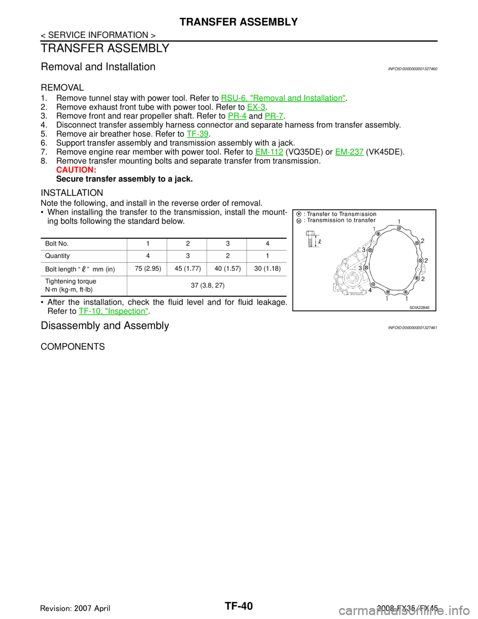
When installing the transfer to the transmission, install the mount-
ing bolts following the standard below.
After the installation, check the fluid level and for fluid leakage. Refer to TF-10, "
Inspection".
Disassembly and AssemblyINFOID:0000000001327461
COMPONENTS
Bolt No. 1234
Quantity 4321
Bolt length “ ” mm (in) 75 (2.95) 45 (1.77) 40 (1.57) 30 (1.18)
Tightening torque
N·m (kg-m, ft-lb) 37 (3.8, 27)
SDIA2284E
3AA93ABC3ACD3AC03ACA3AC03AC63AC53A913A773A893A873A873A8E3A773A983AC73AC93AC03AC3
3A893A873A873A8F3A773A9D3AAF3A8A3A8C3A863A9D3AAF3A8B3A8C
Page 3841 of 3924

WT-1
SUSPENSION
C
DF
G H
I
J
K L
M
SECTION WT
A
B
WT
N
O PCONTENTS
ROAD WHEELS & TIRES
SERVICE INFORMATION .. ..........................2
INDEX FOR DTC ............................................ .....2
DTC No. Index .................................................... ......2
PRECAUTIONS ...................................................3
Precaution for Supplemental Restraint System
(SRS) "AIR BAG" and "SEAT BELT PRE-TEN-
SIONER" ............................................................. ......
3
Precaution .................................................................3
Service Notice or Precaution .....................................4
PREPARATION ...................................................5
Special Service Tool ........................................... ......5
Commercial Service Tool ..........................................5
NOISE, VIBRATION AND HARSHNESS
(NVH) TROUBLESHOOTING .............................
6
NVH Troubleshooting Chart ................................ ......6
ROAD WHEEL ....................................................7
Inspection ............................................................ ......7
ROAD WHEEL TIRE ASSEMBLY ......................8
Balancing Wheels (Bonding Weight Type) .......... ......8
Tire Rotation ..............................................................9
TIRE PRESSURE MONITORING SYSTEM .......10
System Component ............................................. ....10
System Description .................................................10
CAN COMMUNICATION ....................................13
System Description ............................................. ....13
TROUBLE DIAGNOSES ....................................14
Schematic ........................................................... ....14
Wiring Diagram- T/WARN - .....................................15
Control Unit Input/Output Signal Standard ..............17
ID Registration Procedure ................................... ....19
Transmitter Wake Up Operation ..............................20
Self-Diagnosis .........................................................20
CONSULT-III Function (BCM) .................................22
How to Perform Trouble Diagnosis for Quick and
Accurate Repair .......................................................
24
Preliminary Check ...................................................25
Malfunction Code/Symptom Chart ...........................26
TROUBLE DIAGNOSIS FOR SELF-DIAG-
NOSTIC ITEMS .................................................
28
Transmitter or Control Unit (BCM) ...........................28
Transmitter - 1 .........................................................28
Transmitter - 2 .........................................................29
Vehicle Speed Signal ..............................................29
TROUBLE DIAGNOSIS FOR SYMPTOMS ......30
Low Tire Pressure Warning Lamp Does Not Come
On When Ignition Switch Is Turned On ...................
30
Low Tire Pressure Warning Lamp Stays On When
Ignition Switch Is Turned On ............................... ....
30
Low Tire Pressure Warning Lamp Blinks When Ig-
nition Switch Is Turned On ......................................
31
Run-Flat Tire Warning Lamp Stays On When Igni-
tion Switch Is Turned On .........................................
32
Turn Signal Lamp Blinks When Ignition Switch Is
Turned On ...............................................................
32
ID Registration Cannot Be Completed ....................32
REMOVAL AND INSTALLATION .....................33
Transmitter ..............................................................33
SERVICE DATA AND SPECIFICATIONS
(SDS) .................................................................
35
Road Wheel .............................................................35
Tire ..........................................................................35
3AA93ABC3ACD3AC03ACA3AC03AC63AC53A913A773A893A873A873A8E3A773A983AC73AC93AC03AC3
3A893A873A873A8F3A773A9D3AAF3A8A3A8C3A863A9D3AAF3A8B3A8C
Page 3843 of 3924
PRECAUTIONSWT-3
< SERVICE INFORMATION >
C
DF
G H
I
J
K L
M A
B
WT
N
O P
PRECAUTIONS
Precaution for Supplemental Restraint System (SRS) "AIR BAG" and "SEAT BELT
PRE-TENSIONER"
INFOID:0000000001612926
The Supplemental Restraint System such as “A IR BAG” and “SEAT BELT PRE-TENSIONER”, used along
with a front seat belt, helps to reduce the risk or severi ty of injury to the driver and front passenger for certain
types of collision. This system includes seat belt switch inputs and dual stage front air bag modules. The SRS
system uses the seat belt switches to determine the front air bag deployment, and may only deploy one front
air bag, depending on the severity of a collision and whether the front occupants are belted or unbelted.
Information necessary to service the system safely is included in the “SUPPLEMENTAL RESTRAINT SYS-
TEM” and “SEAT BELTS” of this Service Manual.
WARNING:
• To avoid rendering the SRS inoper ative, which could increase the risk of personal injury or death in
the event of a collision which would result in air bag inflation, all maintenance must be performed by
an authorized NISSAN/INFINITI dealer.
Improper maintenance, including in correct removal and installation of the SRS, can lead to personal
injury caused by unintentional act ivation of the system. For removal of Spiral Cable and Air Bag
Module, see the “SUPPLEMEN TAL RESTRAINT SYSTEM”.
Do not use electrical test equipm ent on any circuit related to the SRS unless instructed to in this
Service Manual. SRS wiring harnesses can be identi fied by yellow and/or orange harnesses or har-
ness connectors.
PrecautionINFOID:0000000001327568
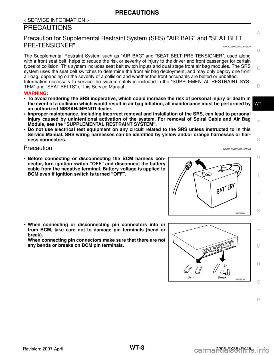
Before connecting or disco nnecting the BCM harness con-
nector, turn ignition switch “OFF” and disconnect the battery
cable from the negative terminal. Battery voltage is applied to
BCM even if ignition sw itch is turned “OFF”.
When connecting or disconnect ing pin connectors into or
from BCM, take care not to damage pin terminals (bend or
break).
When connecting pin connectors make sure that there are not
any bends or breaks on BCM pin terminals.
SEF289H
SEF291H
3AA93ABC3ACD3AC03ACA3AC03AC63AC53A913A773A893A873A873A8E3A773A983AC73AC93AC03AC3
3A893A873A873A8F3A773A9D3AAF3A8A3A8C3A863A9D3AAF3A8B3A8C
Page 3846 of 3924

WT-6
< SERVICE INFORMATION >
NOISE, VIBRATION AND HARSHNESS (NVH) TROUBLESHOOTING
NOISE, VIBRATION AND HARSHNESS (NVH) TROUBLESHOOTING
NVH Troubleshooting ChartINFOID:0000000001327572
Use the chart below to help you find the cause of the sy mptom. If necessary, repair or replace these parts.
×: Applicable
Reference
FAX-4
,
FAX-11
, FSU-5
WT-7WT-8WT-35WT-9—
—
WT-35
NVH in PR section
NVH in RFD section
NVH in FAX and FSU section
NVH in RAX and RSU section Refer to TIRE in this chart.
Refer to ROAD WHEEL in this chart. NVH in FAX, RAX sectionNVH in BR section
NVH in PS section
Possible cause an d SUSPECTED PARTS
Improper installation, looseness
Out-of-round
Unbalance
Incorrect tire pressure
Uneven tire wear
Deformation or damage
Non-uniformity
Incorrect tire size
PROPELLER SHAFT
DIFFERENTIAL
FRONT AXLE AND FRONT SUSPENSION
REAR AXLE AND REAR SUSPENSION
TIRE
ROAD WHEEL
DRIVE SHAFT
BRAKE
STEERING
SymptomTIRE Noise
× ×××××× ×××× ××××
Shake ××××××××××××××
Vibration ×××××××
Shimmy × ××××××× ×× × ××
Judder ××××××× ×××××
Poor quality ride
or handling × ××××× × ×× ×
ROAD WHEEL Noise
× ×× × ××××× ×××
Shake × ×× × × ××× ×××
Shimmy, Judder ×××× ×××××
Poor quality ride
or handling ××× × ×××
3AA93ABC3ACD3AC03ACA3AC03AC63AC53A913A773A893A873A873A8E3A773A983AC73AC93AC03AC3
3A893A873A873A8F3A773A9D3AAF3A8A3A8C3A863A9D3AAF3A8B3A8C
Page 3849 of 3924
ROAD WHEEL TIRE ASSEMBLYWT-9
< SERVICE INFORMATION >
C
DF
G H
I
J
K L
M A
B
WT
N
O P
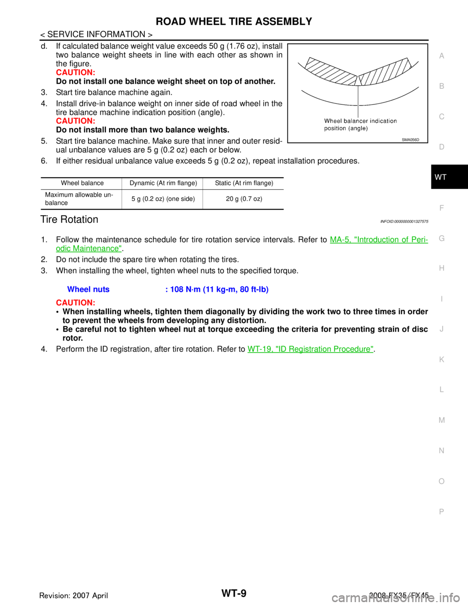
d. If calculated balance weight value exceeds 50 g (1.76 oz), install two balance weight sheets in line with each other as shown in
the figure.
CAUTION:
Do not install one balance weig ht sheet on top of another.
3. Start tire balance machine again.
4. Install drive-in balance weight on inner side of road wheel in the tire balance machine indication position (angle).
CAUTION:
Do not install more than two balance weights.
5. Start tire balance machine. Make sure that inner and outer resid- ual unbalance values are 5 g (0.2 oz) each or below.
6. If either residual unbalance value exceeds 5 g (0.2 oz), repeat installation procedures.
Tire RotationINFOID:0000000001327575
1. Follow the maintenance schedule for tire rotation service intervals. Refer to MA-5, "Introduction of Peri-
odic Maintenance".
2. Do not include the spare tire when rotating the tires.
3. When installing the wheel, tighten wheel nuts to the specified torque.
CAUTION:
When installing wheels, tighten th em diagonally by dividing the work two to three times in order
to prevent the wheels from developing any distortion.
Be careful not to tighten wheel nut at torque exceeding the criteria for preventing strain of disc
rotor.
4. Perform the ID registration, after tire rotation. Refer to WT-19, "
ID Registration Procedure".
Wheel balance Dynamic (At rim flange) Static (At rim flange)
Maximum allowable un-
balance 5 g (0.2 oz) (one side) 20 g (0.7 oz)
SMA056D
Wheel nuts : 108 N·m (11 kg-m, 80 ft-lb)
3AA93ABC3ACD3AC03ACA3AC03AC63AC53A913A773A893A873A873A8E3A773A983AC73AC93AC03AC3
3A893A873A873A8F3A773A9D3AAF3A8A3A8C3A863A9D3AAF3A8B3A8C
Page 3868 of 3924
WT-28
< SERVICE INFORMATION >
TROUBLE DIAGNOSIS FOR SELF-DIAGNOSTIC ITEMS
TROUBLE DIAGNOSIS FOR SELF-DIAGNOSTIC ITEMS
Transmitter or Control Unit (BCM)INFOID:0000000001327589
MALFUNCTION CODE NO. 21, 22, 23 OR 24
1.CHECK CONTROL UNIT
Drive for several minutes. Check all tire pr essures with CONSULT-III “DATA MONITOR ITEM”.
Are all tire pressures displayed 0 kPa?
YES >> GO TO 2.
NO >> GO TO 3.
2.CHECK REMOTE KEYLESS EN TRY RECEIVER CONNECTOR
1. Disconnect remote keyless entry receiver harness connector M98.
2. Check terminals for damage or loose connection.
3. Reconnect harness connector.
OK or NG
OK >> Replace BCM refer to BCS-13, "Removal and Installation of BCM", then GO TO 3.
NG >> Repair or replace remote keyless entry receiver harness connector.
3.ID REGISTRATION
Perform ID registration of all transmitters.
Is there any tire that ID can not be registered to?
YES >> Replace transmitter of the tire, then GO TO 5.
NO >> GO TO 4.
4.VEHICLE DRIVING
Drive at a speed of 40 km/h (25 MPH) or more for several minutes without stopping. Check all tire pressures with CONSULT-III “DATA MONITOR ITEM” within 15 minutes after vehicle speed
becomes 17 km/h (11 MPH).
Does
“DATA MONITOR ITEM” display tire pressure as normal without any warning lamp?
YES >> INSPECTION END
NO >> GO TO 5.
5.ID REGISTRATION AND VEHICLE DRIVING
1. Perform ID registration of all transmitters.
2. Drive at a speed of 40 km/h (25 MPH) or more fo r 3 minutes, and then drive the vehicle at any speed for
10 minutes. Then check all tire pressures with CO NSULT-III “DATA MONITOR ITEM” within 5 minutes.
Does
“DATA MONITOR ITEM” display tire pressure as normal without any warning lamp?
YES >> INSPECTION END
NO >> Go to the inspection applicable to DTC.
Transmitter - 1INFOID:0000000001327590
MALFUNCTION CODE NO. 31, 32, 33, 34, 41, 42, 43, 44, 45, 46, 47 OR 48
1.ID REGISTRATION (CORRECTION OF TRANSMITTER LOCATION)
1. Perform ID registration of all transmitters.
2. Drive at a speed of 40 km/h (25 MPH) or more fo r 3 minutes, and then drive the vehicle at any speed for
10 minutes.
>> GO TO 2.
2.REPLACE TRANSMITTER
1. Check low tire pressure warning condition again, replace malfunctioning transmitter.
2. Perform ID registration of all transmitters.
Can ID registration of all transmitters be completed?
3AA93ABC3ACD3AC03ACA3AC03AC63AC53A913A773A893A873A873A8E3A773A983AC73AC93AC03AC3
3A893A873A873A8F3A773A9D3AAF3A8A3A8C3A863A9D3AAF3A8B3A8C
Page 3870 of 3924
WT-30
< SERVICE INFORMATION >
TROUBLE DIAGNOSIS FOR SYMPTOMS
TROUBLE DIAGNOSIS FOR SYMPTOMS
Low Tire Pressure Warning Lamp Does Not Come On When Ignition Switch Is Turned
On
INFOID:0000000001327593
DIAGNOSTIC PROCEDURE
1.CHECK SELF-DIAGNOSIS RESULTS
1. Select “SELF-DIAG RESULTS” on “SELECT DIAG MODE” screen.
2. Check display contents in self-diagnostic results.
Is
“CAN COMM CIRCUIT” displayed in the self-diagnosis display items?
YES >> Malfunction in CAN communication system. Go to LAN-43, "CAN System Specification Chart".
NO >> No malfunction. GO TO 2.
2.CHECK COMBINATION METER
Check combination meter function.
OK or NG
OK >> GO TO 3.
NG >> Check combination meter. Refer to DI-5, "
System Description".
3.CHECK LOW TIRE PRESSURE WARNING LAMP
Disconnect BCM harness connectors M3 and M4.
Does the warning lamp activate?
YES >> Replace BCM. Refer to BCS-13, "Removal and Installation of BCM".
NO >> Check combination meter and repair or replace.
Low Tire Pressure Warning Lamp Stays On When Ignition Switch Is Turned On
INFOID:0000000001327594
DIAGNOSTIC PROCEDURE
1.CHECK CONNECTOR
1. Disconnect BCM harness connectors M3 and M4.
2. Check terminals for damage or loose connections.
OK or NG
OK >> GO TO 2.
NG >> Repair or replace damaged parts.
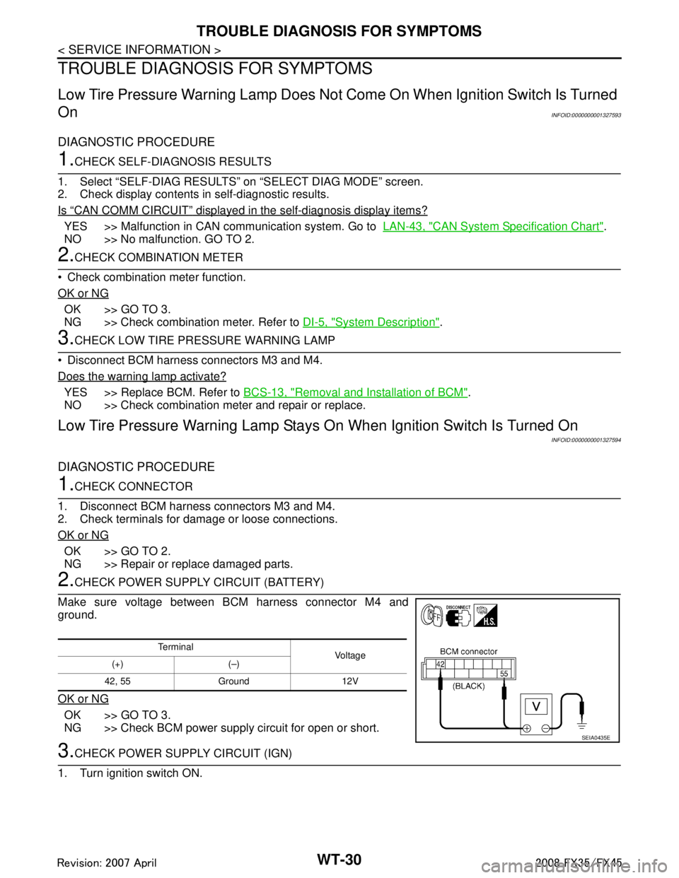
2.CHECK POWER SUPPLY CIRCUIT (BATTERY)
Make sure voltage between BCM harness connector M4 and
ground.
OK or NG
OK >> GO TO 3.
NG >> Check BCM power supply circuit for open or short.
3.CHECK POWER SUPPLY CIRCUIT (IGN)
1. Turn ignition switch ON.
Te r m i n a l Vol tag e
(+) (–)
42, 55 Ground 12V
SEIA0435E
3AA93ABC3ACD3AC03ACA3AC03AC63AC53A913A773A893A873A873A8E3A773A983AC73AC93AC03AC3
3A893A873A873A8F3A773A9D3AAF3A8A3A8C3A863A9D3AAF3A8B3A8C
Page 3873 of 3924
REMOVAL AND INSTALLATIONWT-33
< SERVICE INFORMATION >
C
DF
G H
I
J
K L
M A
B
WT
N
O P
REMOVAL AND INSTALLATION
TransmitterINFOID:0000000001327599
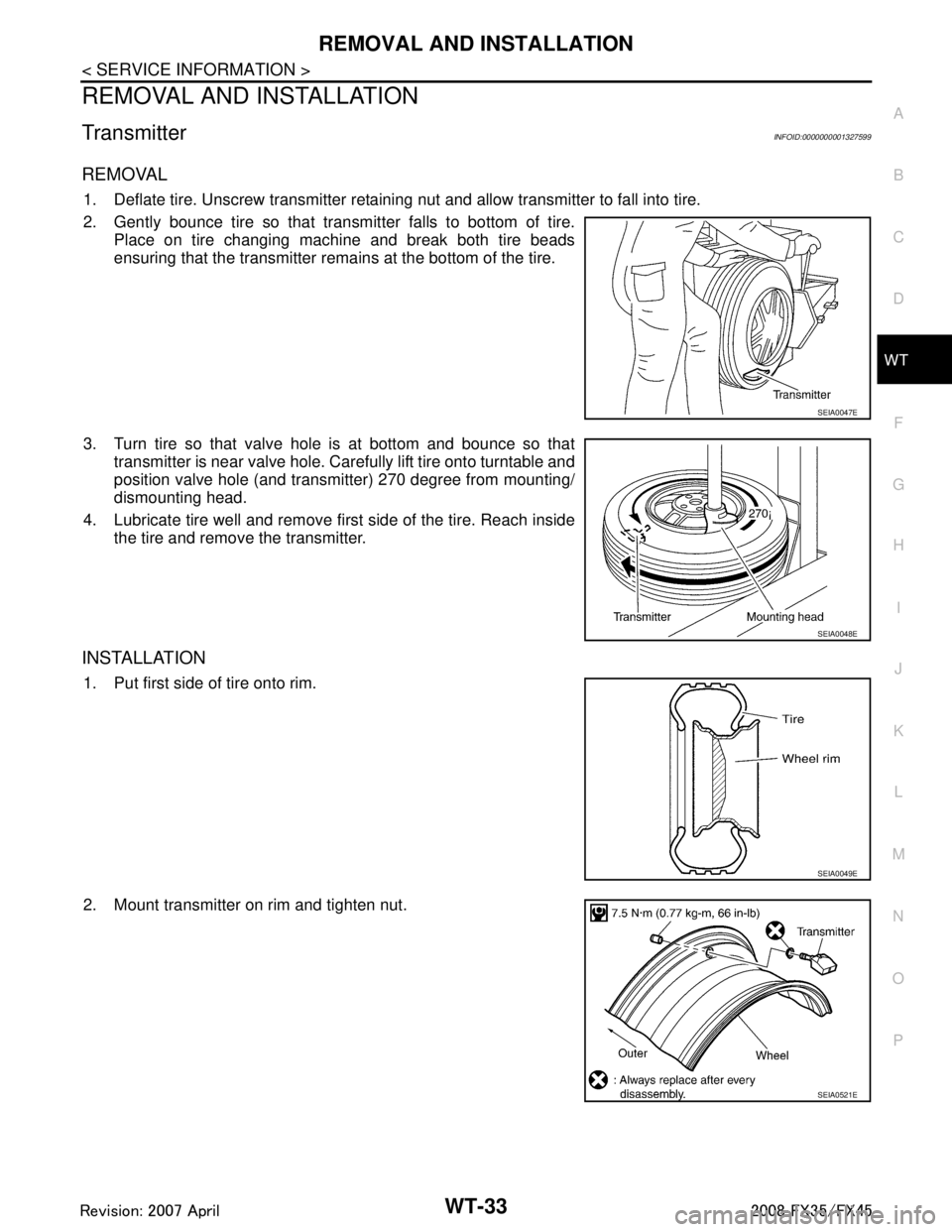
REMOVAL
1. Deflate tire. Unscrew transmitter retaining nut and allow transmitter to fall into tire.
2. Gently bounce tire so that transmitter falls to bottom of tire. Place on tire changing machine and break both tire beads
ensuring that the transmitter rema ins at the bottom of the tire.
3. Turn tire so that valve hole is at bottom and bounce so that transmitter is near valve hole. Carefully lift tire onto turntable and
position valve hole (and transmitter) 270 degree from mounting/
dismounting head.
4. Lubricate tire well and remove first side of the tire. Reach inside the tire and remove the transmitter.
INSTALLATION
1. Put first side of tire onto rim.
2. Mount transmitter on rim and tighten nut.
SEIA0047E
SEIA0048E
SEIA0049E
SEIA0521E
3AA93ABC3ACD3AC03ACA3AC03AC63AC53A913A773A893A873A873A8E3A773A983AC73AC93AC03AC3
3A893A873A873A8F3A773A9D3AAF3A8A3A8C3A863A9D3AAF3A8B3A8C