2008 INFINITI FX35 installation
[x] Cancel search: installationPage 3874 of 3924
WT-34
< SERVICE INFORMATION >
REMOVAL AND INSTALLATION
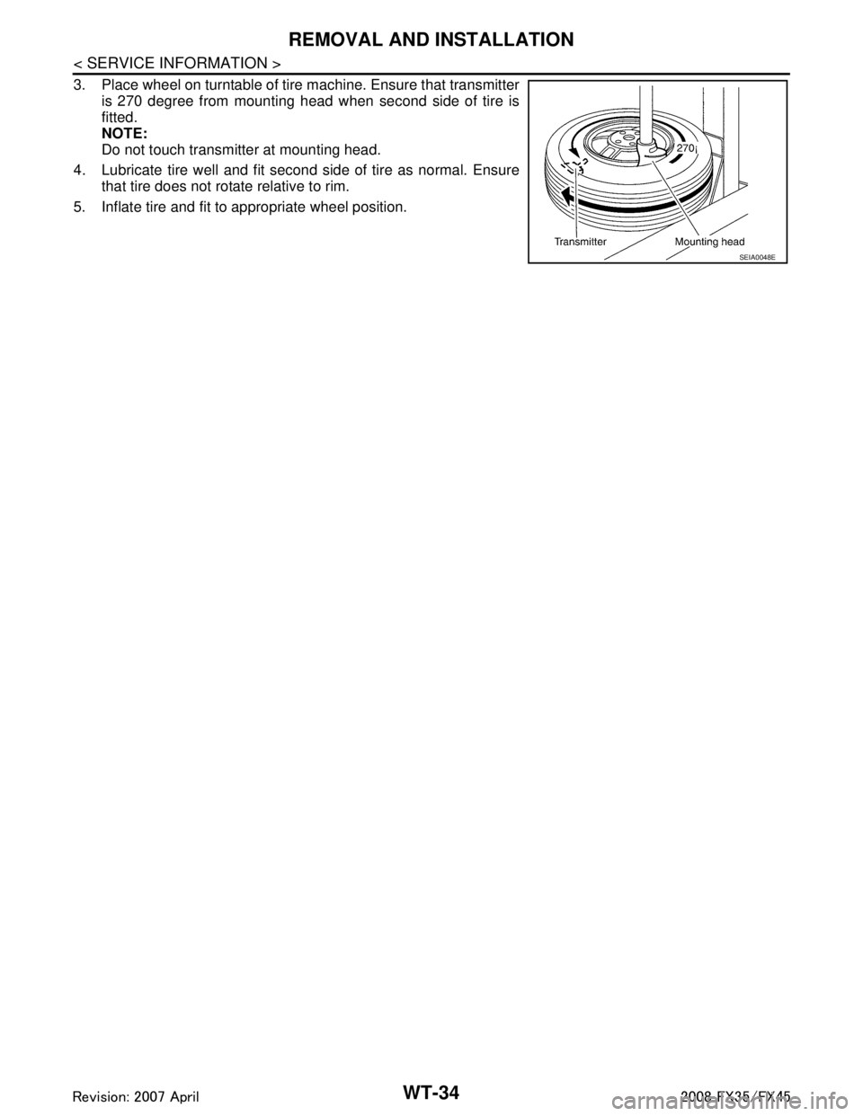
3. Place wheel on turntable of tire machine. Ensure that transmitteris 270 degree from mounting head when second side of tire is
fitted.
NOTE:
Do not touch transmitter at mounting head.
4. Lubricate tire well and fit second side of tire as normal. Ensure that tire does not rotate relative to rim.
5. Inflate tire and fit to appropriate wheel position.
SEIA0048E
3AA93ABC3ACD3AC03ACA3AC03AC63AC53A913A773A893A873A873A8E3A773A983AC73AC93AC03AC3
3A893A873A873A8F3A773A9D3AAF3A8A3A8C3A863A9D3AAF3A8B3A8C
Page 3876 of 3924

WW-1
ELECTRICAL
C
DE
F
G H
I
J
L
M
SECTION WW
A
B
WW
N
O P
CONTENTS
WIPER, WASHER & HORN
SERVICE INFORMATION .. ..........................3
PRECAUTION ................................................ .....3
Precaution for Supplemental Restraint System
(SRS) "AIR BAG" and "SEAT BELT PRE-TEN-
SIONER" ............................................................. ......
3
Precaution for Procedure without Cowl Top Cover ......3
FRONT WIPER AND WASHER SYSTEM ..........4
Component Parts and Harness Connector Loca-
tion ...................................................................... ......
4
System Description ...................................................4
CAN Communication System Description .................6
CAN Communication Unit .........................................7
Schematic .................................................................7
Wiring Diagram - WIPER - ........................................8
Terminal and Reference Value for BCM .................10
Terminal and Reference Value for IPDM E/R .........14
How to Proceed with Trouble Diagnosis .................14
Preliminary Check ...................................................14
CONSULT-III Functions (BCM) ...............................15
CONSULT-III Functions (IPDM E/R) .......................16
Front Wiper Does Not Operate ...............................17
Front Wiper Does Not Return to Stop Position .......18
Only Front Wiper Low Does Not Operate ...............19
Only Front Wiper High Does Not Operate ...............20
Only Front Wiper Intermittent Does Not Operate ....21
Front Wiper Interval Time Is Not Controlled by Ve-
hicle Speed .............................................................
21
Front Wiper Intermittent Operation Switch Posi-
tion Cannot Be Adjusted .........................................
22
Wiper Does Not Wipe When Front Washer Oper-
ates .........................................................................
22
After Front Wiper Operate for 10 Seconds, They
Stop for 20 Seconds, and After Repeating the Op-
eration Five Times, They Become Inoperative ........
22
Front Wiper Does Not Stop .....................................23
Removal and Installation of Front Wiper Arms, Ad-
justment of Wiper Arms Stop Location ....................
23
Removal and Installation of Front Wiper Drive As-
sembly ................................................................. ....
24
Disassembly and Assembly of Front Wiper Drive
Assembly ............................................................. ....
25
Washer Nozzle Adjustment .....................................25
Washer Tube Layout ...............................................27
Removal and Installation of Front Washer Nozzle ....27
Removal and Installation of Front Washer Tube
Joint .........................................................................
27
Inspection of Washer Nozzle ...................................27
Inspection of Front Wiper and Washer Switch Cir-
cuit ...........................................................................
28
Removal and Installation of Front Wiper and
Washer Switch .........................................................
28
Removal and Installation of Washer Tank ...............28
Removal and Installation of Front and Rear Wash-
er Pump ...................................................................
29
REAR WIPER AND WASHER SYSTEM ..........30
Component Parts and Harness Connector Loca-
tion ...........................................................................
30
System Description ..................................................30
Wiring Diagram - WIP/ R - .......................................32
Terminal and Reference Value for BCM ..................33
How to Proceed with Trouble Diagnosis ..................35
Preliminary Check ...................................................36
CONSULT-III Functions (BCM) ...............................36
Rear Wiper Does Not Operate ................................37
Rear Wiper Does Not Return to Stop Position ........39
Only Rear Wiper ON Does Not Operate ..................40
Only Rear Wiper INT Does Not Operate .................40
Wiper Does Not Wipe When Rear Washer Oper-
ates ..........................................................................
40
Rear Wipers Do Not Stop ........................................40
Removal and Installation of Rear Wiper Arm, Ad-
justment of Wiper Arms Stop Location ....................
40
Removal and Installation of Rear Wiper Blade ........41
Removal and Installation of Rear Wiper Motor ........42
Washer Nozzle Adjustment .....................................43
Washer Tube Layout ...............................................43
Removal and Installation of Washer Nozzle ............43
Check Valve ............................................................44
3AA93ABC3ACD3AC03ACA3AC03AC63AC53A913A773A893A873A873A8E3A773A983AC73AC93AC03AC3
3A893A873A873A8F3A773A9D3AAF3A8A3A8C3A863A9D3AAF3A8B3A8C
Page 3877 of 3924

WW-2
Inspection of Front Wiper and Washer Switch Cir-
cuit ..........................................................................
44
Removal and Installation of Rear Wiper and
Washer Switch ........................................................
44
Removal and Installation of Washer Tank ..............44
Removal and Installation of Front and Rear Wash-
er pump ..................................................................
44
POWER SOCKET ..............................................45
Wiring Diagram - P/SCKT - ................................. ...45
Removal and Installation of Front Power Socket -
1 ........................................................................... ...
45
Removal and Installation of Front Power Socket -
2 ..............................................................................
46
Removal and Installation of Rear Power Socket .....46
Removal and Installation of Luggage Room Power
Socket .................................................................. ...
46
HORN .................................................................48
Wiring Diagram - HORN - .................................... ...48
Removal and Installation .........................................48
3AA93ABC3ACD3AC03ACA3AC03AC63AC53A913A773A893A873A873A8E3A773A983AC73AC93AC03AC3
3A893A873A873A8F3A773A9D3AAF3A8A3A8C3A863A9D3AAF3A8B3A8C
Page 3878 of 3924
PRECAUTIONWW-3
< SERVICE INFORMATION >
C
DE
F
G H
I
J
L
M A
B
WW
N
O P
SERVICE INFORMATION
PRECAUTION
Precaution for Supplemental Restraint System (SRS) "AIR BAG" and "SEAT BELT
PRE-TENSIONER"
INFOID:0000000001612916
The Supplemental Restraint System such as “A IR BAG” and “SEAT BELT PRE-TENSIONER”, used along
with a front seat belt, helps to reduce the risk or severi ty of injury to the driver and front passenger for certain
types of collision. This system includes seat belt switch inputs and dual stage front air bag modules. The SRS
system uses the seat belt switches to determine the front air bag deployment, and may only deploy one front
air bag, depending on the severity of a collision and whether the front occupants are belted or unbelted.
Information necessary to service the system safely is included in the “SUPPLEMENTAL RESTRAINT SYS-
TEM” and “SEAT BELTS” of this Service Manual.
WARNING:
• To avoid rendering the SRS inoper ative, which could increase the risk of personal injury or death in
the event of a collision which would result in air bag inflation, all maintenance must be performed by
an authorized NISSAN/INFINITI dealer.
Improper maintenance, including in correct removal and installation of the SRS, can lead to personal
injury caused by unintentional act ivation of the system. For removal of Spiral Cable and Air Bag
Module, see the “SUPPLEMEN TAL RESTRAINT SYSTEM”.
Do not use electrical test equipm ent on any circuit related to the SRS unless instructed to in this
Service Manual. SRS wiring harnesses can be identi fied by yellow and/or orange harnesses or har-
ness connectors.
Precaution for Procedur e without Cowl Top CoverINFOID:0000000001612917
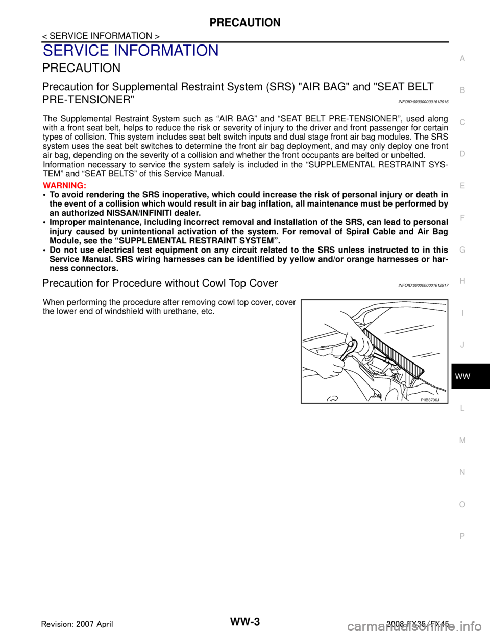
When performing the procedure after removing cowl top cover, cover
the lower end of windshield with urethane, etc.
PIIB3706J
3AA93ABC3ACD3AC03ACA3AC03AC63AC53A913A773A893A873A873A8E3A773A983AC73AC93AC03AC3
3A893A873A873A8F3A773A9D3AAF3A8A3A8C3A863A9D3AAF3A8B3A8C
Page 3893 of 3924
WW-18
< SERVICE INFORMATION >
FRONT WIPER AND WASHER SYSTEM
With CONSULT-III
1. Connect IPDM E/R connector and front wiper motor connector.
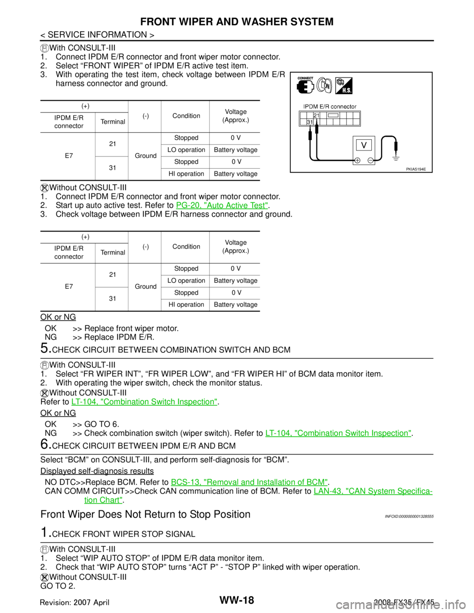
2. Select “FRONT WIPER” of IPDM E/R active test item.
3. With operating the test item , check voltage between IPDM E/R
harness connector and ground.
Without CONSULT-III
1. Connect IPDM E/R connector and front wiper motor connector.
2. Start up auto active test. Refer to PG-20, "
Auto Active Test".
3. Check voltage between IPDM E/R harness connector and ground.
OK or NG
OK >> Replace front wiper motor.
NG >> Replace IPDM E/R.
5.CHECK CIRCUIT BETWEEN COMB INATION SWITCH AND BCM
With CONSULT-III
1. Select “FR WIPER INT”, “FR WIPER LOW”, and “FR WIPER HI” of BCM data monitor item.
2. With operating the wiper switch, check the monitor status.
Without CONSULT-III
Refer to LT-104, "
Combination Switch Inspection".
OK or NG
OK >> GO TO 6.
NG >> Check combination switch (wiper switch). Refer to LT-104, "
Combination Switch Inspection".
6.CHECK CIRCUIT BETWEEN IPDM E/R AND BCM
Select “BCM” on CONSULT-III, and perform self-diagnosis for “BCM”.
Displayed self
-diagnosis results
NO DTC>>Replace BCM. Refer to BCS-13, "Removal and Installation of BCM".
CAN COMM CIRCUIT>>Check CAN communi cation line of BCM. Refer to LAN-43, "
CAN System Specifica-
tion Chart".
Front Wiper Does Not Return to Stop PositionINFOID:0000000001328555
1.CHECK FRONT WIPER STOP SIGNAL
With CONSULT-III
1. Select “WIP AUTO STOP” of IPDM E/R data monitor item.
2. Check that “WIP AUTO STOP” turns “ACT P” - “STOP P” linked with wiper operation.
Without CONSULT-III
GO TO 2.
(+)
(-) Condition Vol tag e
(Approx.)
IPDM E/R
connector Te r m i n a l
E7 21
Ground Stopped 0 V
LO operation Battery voltage
31 Stopped 0 V
HI operation Battery voltage
(+) (-) Condition Vol tag e
(Approx.)
IPDM E/R
connector Te r m i n a l
E7 21
Ground Stopped 0 V
LO operation Battery voltage
31 Stopped 0 V
HI operation Battery voltage
PKIA5194E
3AA93ABC3ACD3AC03ACA3AC03AC63AC53A913A773A893A873A873A8E3A773A983AC73AC93AC03AC3
3A893A873A873A8F3A773A9D3AAF3A8A3A8C3A863A9D3AAF3A8B3A8C
Page 3896 of 3924
FRONT WIPER AND WASHER SYSTEMWW-21
< SERVICE INFORMATION >
C
DE
F
G H
I
J
L
M A
B
WW
N
O P
2. Disconnect IPDM E/R connector and front wiper motor connector.
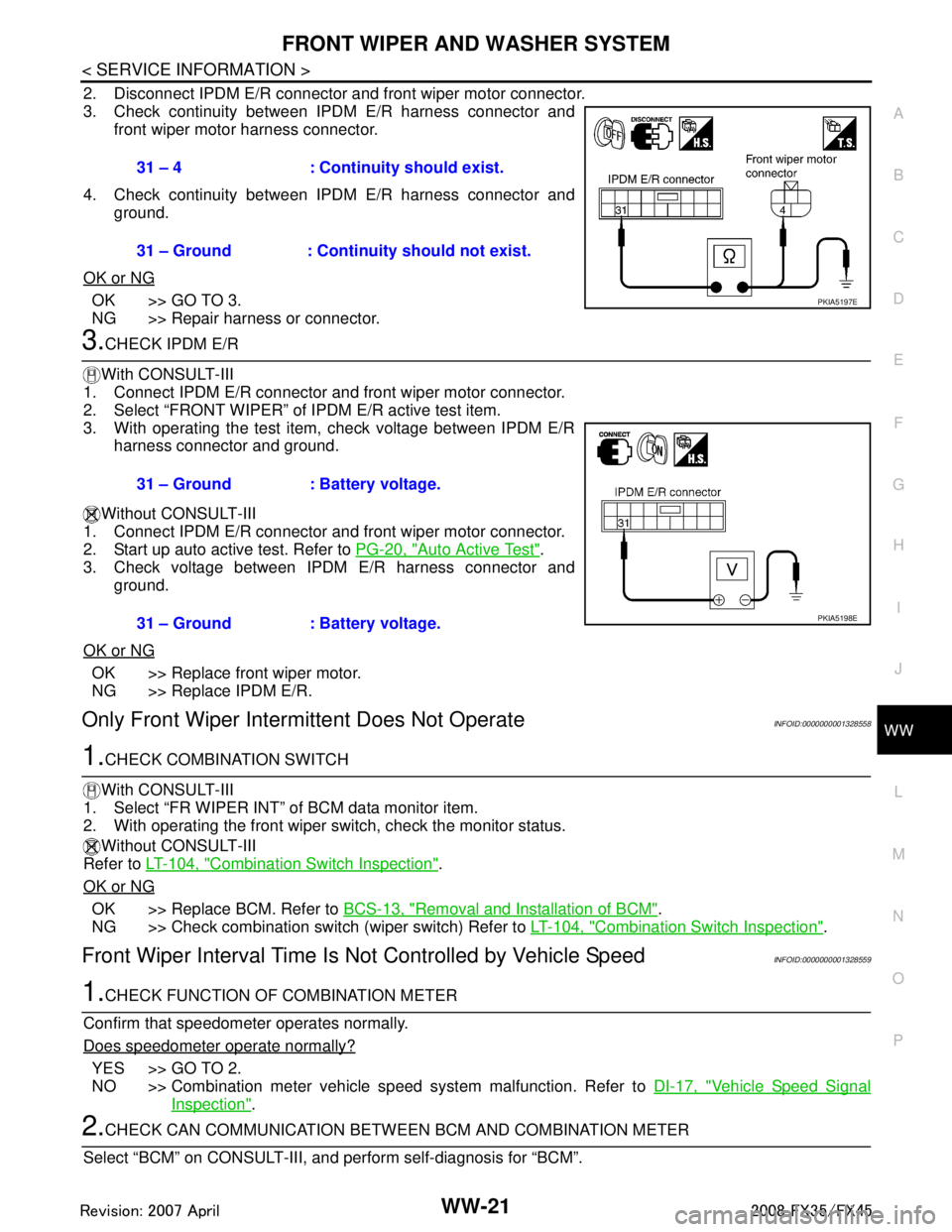
3. Check continuity between IPDM E/R harness connector and front wiper motor harness connector.
4. Check continuity between IPDM E/R harness connector and ground.
OK or NG
OK >> GO TO 3.
NG >> Repair harness or connector.
3.CHECK IPDM E/R
With CONSULT-III
1. Connect IPDM E/R connector and front wiper motor connector.
2. Select “FRONT WIPER” of IPDM E/R active test item.
3. With operating the test item, check voltage between IPDM E/R harness connector and ground.
Without CONSULT-III
1. Connect IPDM E/R connector and front wiper motor connector.
2. Start up auto active test. Refer to PG-20, "
Auto Active Test".
3. Check voltage between IPDM E/R harness connector and
ground.
OK or NG
OK >> Replace front wiper motor.
NG >> Replace IPDM E/R.
Only Front Wiper Intermi ttent Does Not OperateINFOID:0000000001328558
1.CHECK COMBINATION SWITCH
With CONSULT-III
1. Select “FR WIPER INT” of BCM data monitor item.
2. With operating the front wiper switch, check the monitor status.
Without CONSULT-III
Refer to LT-104, "
Combination Switch Inspection".
OK or NG
OK >> Replace BCM. Refer to BCS-13, "Removal and Installation of BCM".
NG >> Check combination switch (wiper switch) Refer to LT-104, "
Combination Switch Inspection".
Front Wiper Interval Time Is Not Controlled by Vehicle SpeedINFOID:0000000001328559
1.CHECK FUNCTION OF COMBINATION METER
Confirm that speedometer operates normally.
Does speedometer operate normally?
YES >> GO TO 2.
NO >> Combination meter vehicle speed system malfunction. Refer to DI-17, "
Vehicle Speed Signal
Inspection".
2.CHECK CAN COMMUNICATION BETWEEN BCM AND COMBINATION METER
Select “BCM” on CONSULT-III, and perform self-diagnosis for “BCM”.
31 – 4 : Continui
ty should exist.
31 – Ground : Continuity should not exist.
PKIA5197E
31 – Ground : Battery voltage.
31 – Ground : Battery voltage.
PKIA5198E
3AA93ABC3ACD3AC03ACA3AC03AC63AC53A913A773A893A873A873A8E3A773A983AC73AC93AC03AC3
3A893A873A873A8F3A773A9D3AAF3A8A3A8C3A863A9D3AAF3A8B3A8C
Page 3897 of 3924
WW-22
< SERVICE INFORMATION >
FRONT WIPER AND WASHER SYSTEM
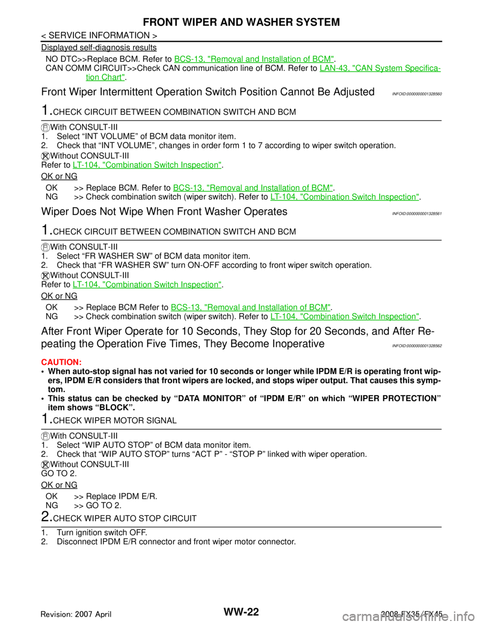
Displayed self-diagnosis results
NO DTC>>Replace BCM. Refer to BCS-13, "Removal and Installation of BCM".
CAN COMM CIRCUIT>>Check CAN communi cation line of BCM. Refer to LAN-43, "
CAN System Specifica-
tion Chart".
Front Wiper Intermittent Operation S witch Position Cannot Be AdjustedINFOID:0000000001328560
1.CHECK CIRCUIT BETWEEN COMB INATION SWITCH AND BCM
With CONSULT-III
1. Select “INT VOLUME” of BCM data monitor item.
2. Check that “INT VOLUME”, changes in order fo rm 1 to 7 according to wiper switch operation.
Without CONSULT-III
Refer to LT-104, "
Combination Switch Inspection".
OK or NG
OK >> Replace BCM. Refer to BCS-13, "Removal and Installation of BCM".
NG >> Check combination switch (wiper switch). Refer to LT-104, "
Combination Switch Inspection".
Wiper Does Not Wipe When Front Washer OperatesINFOID:0000000001328561
1.CHECK CIRCUIT BETWEEN COMB INATION SWITCH AND BCM
With CONSULT-III
1. Select “FR WASHER SW” of BCM data monitor item.
2. Check that “FR WASHER SW” turn ON-OFF according to front wiper switch operation.
Without CONSULT-III
Refer to LT-104, "
Combination Switch Inspection".
OK or NG
OK >> Replace BCM Refer to BCS-13, "Removal and Installation of BCM".
NG >> Check combination switch (wiper switch). Refer to LT-104, "
Combination Switch Inspection".
After Front Wiper Operate for 10 Seconds, They Stop for 20 Seconds, and After Re-
peating the Operation Five Time s, They Become Inoperative
INFOID:0000000001328562
CAUTION:
When auto-stop signal has not varied for 10 seconds or longer while IPDM E/R is operating front wip-
ers, IPDM E/R considers that front wipers are locked, and stops wiper output. That causes this symp-
tom.
This status can be checked by “DATA MONITOR” of “IPDM E/R” on which “WIPER PROTECTION”
item shows “BLOCK”.
1.CHECK WIPER MOTOR SIGNAL
With CONSULT-III
1. Select “WIP AUTO STOP” of BCM data monitor item.
2. Check that “WIP AUTO STOP” turns “ACT P” - “STOP P” linked with wiper operation.
Without CONSULT-III
GO TO 2.
OK or NG
OK >> Replace IPDM E/R.
NG >> GO TO 2.
2.CHECK WIPER AUTO STOP CIRCUIT
1. Turn ignition switch OFF.
2. Disconnect IPDM E/R connector and front wiper motor connector.
3AA93ABC3ACD3AC03ACA3AC03AC63AC53A913A773A893A873A873A8E3A773A983AC73AC93AC03AC3
3A893A873A873A8F3A773A9D3AAF3A8A3A8C3A863A9D3AAF3A8B3A8C
Page 3898 of 3924
FRONT WIPER AND WASHER SYSTEMWW-23
< SERVICE INFORMATION >
C
DE
F
G H
I
J
L
M A
B
WW
N
O P
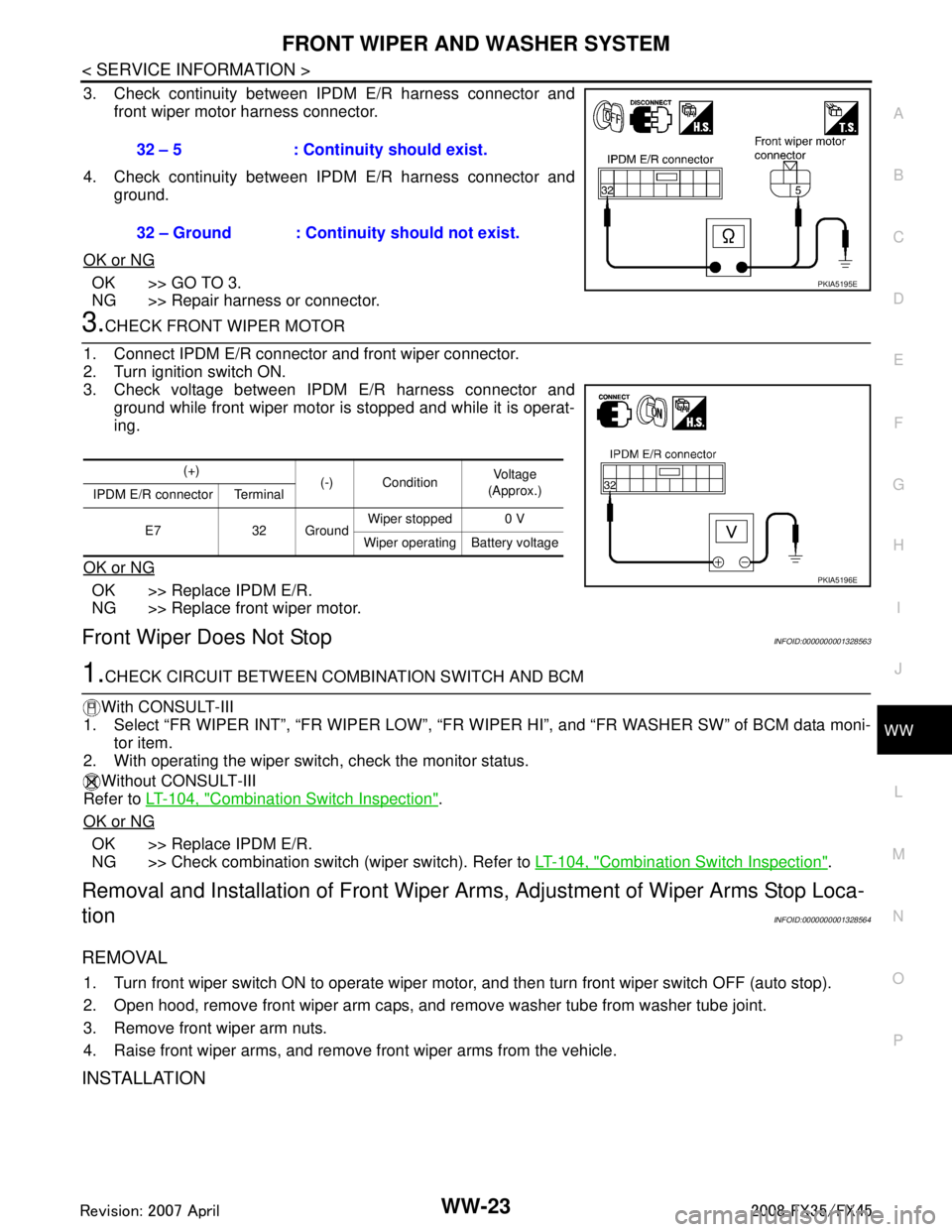
3. Check continuity between IPDM E/R harness connector and front wiper motor harness connector.
4. Check continuity between IPDM E/R harness connector and ground.
OK or NG
OK >> GO TO 3.
NG >> Repair harness or connector.
3.CHECK FRONT WIPER MOTOR
1. Connect IPDM E/R connector and front wiper connector.
2. Turn ignition switch ON.
3. Check voltage between IPDM E/R harness connector and ground while front wiper motor is stopped and while it is operat-
ing.
OK or NG
OK >> Replace IPDM E/R.
NG >> Replace front wiper motor.
Front Wiper Does Not StopINFOID:0000000001328563
1.CHECK CIRCUIT BETWEEN COMB INATION SWITCH AND BCM
With CONSULT-III
1. Select “FR WIPER INT”, “FR WI PER LOW”, “FR WIPER HI”, and “FR WASHER SW” of BCM data moni-
tor item.
2. With operating the wiper switch, check the monitor status.
Without CONSULT-III
Refer to LT-104, "
Combination Switch Inspection".
OK or NG
OK >> Replace IPDM E/R.
NG >> Check combination switch (wiper switch). Refer to LT-104, "
Combination Switch Inspection".
Removal and Installation of Front Wiper Arms, Adjustment of Wiper Arms Stop Loca-
tion
INFOID:0000000001328564
REMOVAL
1. Turn front wiper switch ON to operate wiper moto r, and then turn front wiper switch OFF (auto stop).
2. Open hood, remove front wiper arm caps, and remove washer tube from washer tube joint.
3. Remove front wiper arm nuts.
4. Raise front wiper arms, and remove front wiper arms from the vehicle.
INSTALLATION
32 – 5 : Continuity should exist.
32 – Ground : Continuity should not exist.
PKIA5195E
(+) (-) Condition Vo l ta g e
(Approx.)
IPDM E/R connector Terminal
E7 32 Ground Wiper stopped 0 V
Wiper operating Battery voltage
PKIA5196E
3AA93ABC3ACD3AC03ACA3AC03AC63AC53A913A773A893A873A873A8E3A773A983AC73AC93AC03AC3
3A893A873A873A8F3A773A9D3AAF3A8A3A8C3A863A9D3AAF3A8B3A8C