Page 361 of 404

_________________________________________________ F_ u_ s_ e_s _ a_n _d_ b_ u
_ lb_ s _ __.11111
[ i J Tips
You are well advised to keep a supply of spare fuses in your vehicle.
Fuses with the proper ampere ratings are available at your Audi
dealer. •
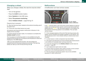
Fuse Location , Instrument Panel left
Fig . 293 Fuse panel
layout
Some of the equipment items listed are optional or only available on
certain model configurations.
Note that the following table is accurate at the time of going to
press and is subject to change. In the event of discrepancies, the
label on the inside of the cover always takes precedence.
The power windows and the power seats are protected by circuit
breakers, which automatically reset after a few seconds after the
overload -for example if a window is frozen -has been remedied.
No. Equipment
1 Garage door opener (Homelinkl 5
2
Parking assist system 5
3
Parking assist system 5
4
Headlight range control/light control device 10
No.
5
6
7
8
9
10
11
12
13
14
15
16
17
18
19
20
21
22
23
24
25
26
27
28
29
Equipment Amps
Instrument cluster 5
Steering column electronics system control 10
Diagnostic connector 5
Diagnostic connector/oil level sensor 5
ESP control unit/steering angle sensor 5
Instrument cluster 5
Audi lane assist 10
Brake light switch 5
Telephone/cell phone 10
Vacant
Access/start control module
5
RSE system 10
Adaptive Cruise Control 5
Heated washer jets 5
Vacant
Tire pressure mon itoring system
5
Vacant
Brake light switch
5
Cell phone preparation 5
Horn 15
Windshield wiper system 40
Vacant Electronic Stabilization Program (ESP)
25
Vacant
Switch illumination
1
Vehicle care Do-it-yourself service irechnical data
Page 362 of 404

111!1....__F_ u_ s_ e_s _ a_n _ d_ b_ u_lb _ s _______________________________________________ _
No. Equipm ent
30 Vacant
31
32
33
34
35
36
37
38
39
40
On board power supply, light control (right headlight)
Vacant L eft rear footwell heater
Vacant
Vacant
Audi side assist Cooler
Onboard power supply, light control (left head light)
Door control unit, driver 's side
Power ste ering column adjustment
41 Door control unit, rear left
Amps
30
25
5
15
30
7.5
25
7.5
25 42 Access/start control module
43 Adaptive Light, left ______ _,., __
--44 Adaptive Light, right 10 10
.
•
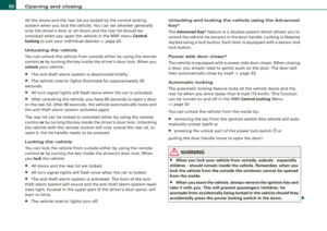
Fuse Location
, Instrument Panel right
Fig. 29 4 Fuse pa nel
lay ou t
Some of the equipment items listed are optional or only available on
certain model configurations.
Not e th at th e follo wing t able is acc urate at th e tim e o f going to
pr ess and is s ubject t o c hange . In th e event o f di screp ancies, the
la bel on the in side of the cov er a lways ta k es prece de nce.
The power window regulators and the power seats are protected by
cir cuit br eak ers, which automatically reset after a few seconds after
the over load -for example if a window is frozen - has been reme
died .
No. Equipm ent
1 Parking brake
2
3
4
5
6
7
Air conditioning Shi ft gate
Vacant
Engine control
Oxygen senso r before the three-way
catalytic converter
Oxygen sensor behind the three-way
catalytic converter
Amp s
5
10
5
15
15
15
-
Page 363 of 404

_________________________________________________ F_ u_ s_ e_s _ a_n _d_ b_ u
_ lb_ s _ __,_
-
No . II Equipm ent
8 Engine control, auxiliary water pump
9
10 C
limate control front /rear, dash panel buttons
Suspension level control system
(Adaptive Air Suspension)
11 Light and rain sensor
1 2 Display -/control unit
13 Roof electronics control unit
CD/DVD d rive
15 Energy managemen t
16 Vacant
17 Radiator fan e lectronics
18 Airbag front passenger recognition
(weight sensor)
19 Vacant
20 Heated/ventilated seats
21 Engine control module
22 Vacant
23 Parking brake (switch)
24 Vehicle electrical syste m
25
26
27
Automatic transmission Air condi tioning water valves wate r pump,
rea r climate control
Sunroof
28 Engine control module
29 Fuel injectors
30 Ignition coils
Amps
10
5
1 0
5
5
10
5
5
5
5
5
5
5
1 0
15
10
20
5
1 5
30
-
No . Equipm ent
31 Fuel pump , right/fue l pump e lectronics
32 Automatic transmission
33
34
Right rear footwe ll heater
Heated/ventila ted seats, rear
35 Heated/ventilated seats, front
36 Cigarette lighter, front
37 Cigarette lighter, rear/socket, rear
38 Auxil iary cooler fan
39 Door contro l unit, front right
40 Brake booster
41 Door contro l unit, rear right
42 Vacant
43 Headlight washer system
44 A ir co nditioning heater fan
Amps
20/40
5
25
20
20
20
20/25 20
7.5
1 5
7.5
30
30 •
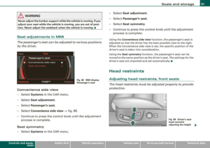
Fuse Location , Luggage Compartment left
0
Fig . 2 95 Fuse pan el
l a you t _.
Vehicle care Do-it-yourself service irechnical data
Page 364 of 404

111!1....__F_ u_ s_ e_s _ a_n _ d_ b_ u_lb _ s _______________________________________________ _
No. Equipment Amps
1
Vacant
2 Vacant
3 Vacant
4 Vacant
5 Digital sound system control module 30
6 Navigation 5
7
TV Tuner 10
8 Rear -view camera 5
9 Communications box 5
10 Subwoofer in rear window shelf (BOSE)/ 15/30 Amplifier (Bang & Olufsen)
--
1 1 Socket 20
12
Vacant
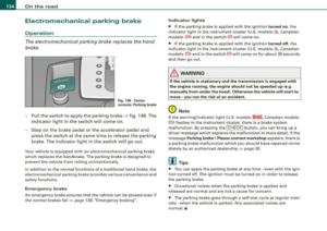
Fuse Location, Luggage Compartment right
Fig. 296 Fuse pan el
l a y out
I
•
N o. Equipm ent Amps
1
Vacant
2 Fuel pump, left 20
3 Vacant
4 Vacant
5 Central control module for comfort system 20 (left light)
-
6 Central control module for comfo rt system 10 (right light)
Central control module for comfort system 7 (door closing) 20
8 Electronic parking brake control module, left 30
9 Electronic parking brake control module, right 30
Vacant
11 Vacant
12 Vacant
Bulbs
Replacing light bulbs
For your safety, we recommend that you have your autho
rized Audi dealer replace burned out bulbs for you.
It is becoming increasing ly more and more difficult to replace
vehic le light bulbs since in many cases, other parts of the car must
first be removed before you are able to get to the bu lb. This applies
especially to the light bulbs in the front of your car which you can
only reach through the engine compartment.
•
Sheet metal and bulb holders can have sharp edges that can cause
serious cuts, and parts must be correctly taken apart and then prop -
...
Page 365 of 404

_________________________________________________ F_ u_ s_ e_s _ a_n _ d_ b_ u_lb _ s __ lllll
•
erly put back together to help prevent breakage of parts and long
t erm damage from water t hat can enter housings that have not
been properly resealed .
For your safety, we recommend that you have your authorized Audi
dea ler replace any bu lbs for you, s ince your dealer has the proper
tools, the correct bu lbs and the expertise .
Ga s di scharge lamp s (Xenon light s):
Due to the high e lectrical voltage, have the bu lbs replaced by a qual
ified technician. Headlights with Xenon light can be identified by the
h ig h voltage st icker .
& WARNING
Contact with high -voltage component s of the ele ctric al sys tem
and improper repla cement of ga s di sch arge (Xenon ) headlight
bulb s can cau se ser iou s per son al injury and death .
• Xen on bulbs are pres suri zed and can explode when be ing
c h anged .
• Changing Xenon lamp s require s the special training , in struc
tion s and equipment .
• Only an authorized Audi dealer or othe r qualified work shop
s hould ch ange the bulbs in g as dis charge l amp s.
& WARNING
There are parts with sharp edges on the open ings and on the bulb
holder s th at can c ause seriou s cuts.
• If you are uncert ain about what to do , have the work perform ed
b y a n author ized Audi de aler or other qu alified work shop. Seri ous
personal injur y ma y re sult from improperl y perfo rmed work.
[ i] Tips
• I f you must replace the light bulbs yourself, a lways remember
that t he engine compartment of any vehicle is a hazardous area to work in
. Always read and heed all
WARNINGS=> page 299, "Engine
compartment" =>& .
• I t is best to ask your authorized Audi dealer whenever you need
t o change a bulb. •
Do-it -yourself service
Page 366 of 404

___ E
_ m_ e_r-=g =-e_ n_c ..:y,_ s_ i_ t _u _a_ t_ i_ o _n_ s _______________________________________________ _
Emergency situations
General
This section is intended for trained emergency crews and per sonnel
who have the necessary tools and equipment to perform these operations.
•
Starting by pushing or towing
0 Note
Yo ur vehicle is equipped wi th an auto matic trans mis sio n. C onse
quent ly, the engine cannot be started by pushing or tow ing .•
Starting with jumper cables
If n ece ssar y, the eng in e c an b e star ted by connecting it to
the battery of anoth er veh icle .
If th e engin e shou ld fail to start because of a discharged or weak
ba ttery , the bat te ry can be co nnected to the ba ttery of
another
vehic le, usin g a pair of jumper cables to start the engine.
Jumper cables
Use on/yjumper cabl es of sufficient ly lar gecross section to carry the
s tarte r current safe ly . R efe r to th e manu fac tur er's speci fica tions.
Us e on ly jump er cabl es w it h
insulate d terminal clamps w hic h are
distinct ly marked:
plus (+l cable in m ost c ases c olor ed red
minus
(-l cable in most cases co lored black .
& WARNING
Batteries contain electricity , acid , and gas. Any of these can cause
very serious or fatal injury. Follow the instructions below for safe
handling of your vehicle 's battery.
• Always shield your eyes and avoid leaning over the battery
whenever possible .
• A discharged battery can freeze at temperatures just below
32 °F (0 °C l. Before connecting a jumper cable, you must thaw the
frozen battery completely , otherwise it could explode .
• Do not allow battery a cid to contact eyes or skin . Flush any
contacted area with water immediately .
• Improper use of a booster battery to start a vehicle may cause
an explosion.
• Vehicle batteries generate e xplosive gases . Keep sparks, flame
and lighted cigarettes away from batteries.
• Do not try to jump start any vehicle with a low ac id level in the
battery.
• The voltage of the booster battery must also have a 12-Volt
rating . The capacity (Ahl of the booster battery should not be
lower than that of the discharged battery . Use of batteries of
different voltage or substantially different
" Ah " rating may cause
an explosion and personal injury .
• Never charge a frozen battery. Gas trapped in the ice may cause
an explosion .
• Never charge or use a battery that has been frozen . The battery
case may have be weakened.
• Use of batteries of different voltage or substantially different
capacity (Ah) rating may cause an explosion and injury . The
capacity (Ah l of the booster battery should not be lower than that
of the discharged battery .
...,
Page 367 of 404

________________________________________________ E=..:.; m:..:.:: e:.:.r.::g ~e::.:..: n:.:c ~y~ s:: i:.:t .=u :.:a:. t:: i:.:o :.:n..:.:: s~_JIIII
fl::. WARNING (continued)
• Before you check anything in the engine compartment, always
read and heed all
WARNINGS~ page 299, "Engine compartment".
0 Note
• Applying a higher voltage booster battery will cause expensive
damage to sensitive electronic components, such as control units,
relays, radio, etc .
• There must be no electrical contact between the vehicles as
otherwise current could already start to flow as soon as the positive
( + ) terminals are connected.
[ i) Tips
• The discharged battery must be properly connected to the
vehicle's electrical system. When jump starting or charging the battery , never connect the negative ground cable to the battery
negative post because the battery manager system must be able to
detect the battery's state of charge. Always connect the negative
ground cable to the negative ground post of the battery manager
control unit .•
Use of jumper cables
Make sure to connect the jumper cable clamps in exactly
the order described below!
Fig. 297 Jump starting
with the battery of
another vehicle: A -
discharged vehicle
battery, B -booster
battery
The procedure described below for connecting jumper
cables is intended to provide a jump start for your vehicle.
Vehicle with discharged battery:
-Turn off lights and accessories, move lever of automatic
transmission to
N (Neutral) or P (Park) and set parking
brake.
Connect POSITIVE (+) to POSITIVE (+) (red)
1. Connect one end to the positive terminal => fig. 297 G)
of your battery @.
2. Connect the other end to the positive terminal
@ of the
booster battery
@.
Connect NEGATIVE (-) to NEGATIVE (-) (black)
3. Connect one end to the negative terminal @ of the
booster battery
@.
Vehicle care Do-it-yourself service irechnical data
Page 368 of 404

____ E_m _ e_r-=g =- e_ n_c ..: y,_ s_ i_ t _u _a_ t_ i_ o _ n_ s ______________________________________________ _
4. Connect the other end to the negative ground post of the
battery manager control unit located next to the battery.
Starting the engine
-Start the engine of the vehicle with the booster battery.
Run the engine at a moderate speed.
- Start engine with discharged vehicle battery in the usual
manner .
- If the engine fails to start: do not keep the starter
cranking for longer than 10 seconds. Wait for about 30
seconds and then try again.
- With engine running, remove jumper cables from both vehicles in the exact
reverse order.
The battery is vented to the outside to prevent gases from entering
the vehicle interior . Make sure that the jumper clamps are well
connected with their metal ports in full contact with the battery
terminals.
& WARNING
To avoid serious personal injury and damage to the vehicle, heed all warnings and instructions of the jumper cable manufacturer. If
in doubt, call for road service.
• Jumper cables must be long enough so that the vehicles do not
touch.
• When connecting jumper cables, make sure that they cannot
get caught in any moving parts in the engine compartment.
• Before you check anything in the engine compartment, always
read and heed all
WARNINGS ~ page 299, "Engine compartment".
0 Note
Improper hook -up of jumper cables can ruin the generator. •
Always connect POSITIVE(+) to POSITIVE(+), and NEGATIVE(-) to
NEGATIVE( -) ground post of the battery manager control unit.
• Check that all screw plugs on the battery cells are screwed in
firmly. If not, tighten plugs prior to connecting clamp on negative
battery terminal.
• Please note that the procedure for connecting a jumper cable as
described above applies specifically to the case of your vehicle
being jump started. When you are giving a jump start to another
vehicle, do not connect the negative(-) cable to the negative(-)
terminal on the discharged
battery @~ page 365, fig. 297. Instead,
securely connect the negative(-) cable to either a solid metal
component that is firmly bolted to the engine block or to the engine
block itself. If the battery that is being charged does not vent to the
outside, escaping battery gas could ignite and explode! •
Emergency towing with commercial
tow truck
General hints
Your Audi requires special handling for towing.
The following information is to be used by commercial tow truck
operators who know how to operate their equipment safely.
• Never tow your Audi, towing will cause damage to the engine
and transmission.
• Never wrap the safety chains or winch cables around the brake
lines.
• To prevent unnecessary damage, your Audi must be transported
with a flat bed truck.
• To load the vehicle on to the flat bed, use the towing loop found
in the vehicle tools and attach to the front or rear anchorage
~ page 367 and ~ page 368 . .,,_