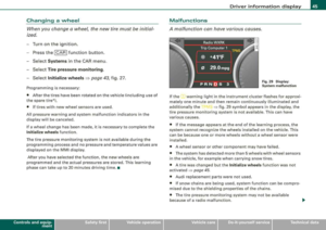
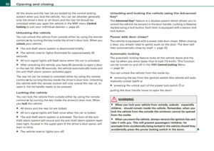
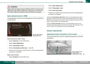
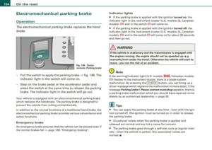
Page 25 of 404

If the ABS, ESP and brake force distribution fail, the ABS indicator
l ig ht ABS (USA
mod els)/ 0 (Cana da mod els) and t he ESP i nd ica tor
light
f;. come on along with the brake system ma lfunction light
BRAKE (USA m ode ls)/ (@ (C an ada model s). The mes sage Brake fault !
Drive carefully to nearest workshop appears in the instrument
cluster d isp lay and three consec utive wa rning tones
sound =>& .
& WARNING
• USA models: If the BRAKE warning light , the $';. warning light and
the ABS warning light come on together , the rear wheels could
lock up first under hard braking . Rear wheel lock-up can cause loss
of vehicle control and an accident . Ha ve your vehicle repaired
immediately by your authorized Audi dealer or a qualified work
shop. Drive slowly and avoid sudden , hard brake applications.
• Canada model s: If the brake warning light
(CD) , the ~ warning
light and the ABS warning light
8 c ome on together , the rear
wheels could lock up first under hard braking. Rear wheel lock-up
can cau se los s of vehicle control and an accident. Have your
vehicle repaired immediately by your authorized Audi dealer or a qualified workshop. Drive slowly and avoid sudden , hard brake
applications.
• If the brake warning /indicator light does not go out after a few
seconds and the parking brake released , or lights up while you are
driving , the fluid level in the brake fluid reservoir is too low. If you
believe that it is safe to do so , pro ceed immediately at low speed
to the nearest authorized Audi dealer or qualified repair facility and have the brake system inspected .
• Always keep in mind that after several brake applications, you
will need greater pressure on the brake pedal to stop your vehicle.
Do not rely on strained brakes to respond with maximum stopping
power in critical situations . You must allow for increased braking
distances . The extra distance used up by fading brakes could lead
to an a ccident . •
Controls and equip ment
Instruments and warning /indicator lights
Page 26 of 404

Driver inf orma tio n displ ay
Driver information display
Introduction
General notes
The driver information display inside the instrument
cluster provides you, the driver, with much useful infor
mation.
F ig. 8 Inst rum ent
c luster : center d is pl ay
Information from the Driver Information System is shown in the
display in the center of the instrument cluster.
When you turn on the ignition and while you are driving, some func
tions and vehicle components are scanned for their operating status. Malfunctions or required service procedures are signalled
audibly and shown by red and yellow lighted symbols and
reminders to the driver in the display.
The driver is also shown information about radio and CD operation and directions for the navigation system. You can find additional
information on these subjects in the MMI manual.
The Driver Information System provides the fol lowing functions : Sound system display
=> page25
Outside air temperature => page25
Digital speedometer
=> page25
Door open indicator => page26
Defective light bulb
=> page26
Service interval display => page27
Auto Check system
=> page28
Driver information => page29
Speed limiter
=> page28
Trip computer => page38
Tire pressure monitoring
=> page 40
Selector lever position => page 764
[ i ] Tips
In the event of a malfunction either a red or yellow icon appears in
the display. Red symbols indicate
D ang er => page 30. Yellow
symbols indicate a
W arning => page 34 . •
Page 27 of 404

Sound system display
Fig. 9 Display : sound
system
T he name of the radio station you are tuned to o r its frequency and
r ece ptio n ra n ge are s hown i n the upper area o f the di sp la y.
W hen the C D is i n us e, th e t itl e of the track being played is s hown .
T he nu mber of the CD (CD 1 to CD6) currently being played is al so
sho wn. •
Outside temperature display
Fig . 1 O Display:
outside temperature
At t emp eratu re s below 41 °F ( +5 °C l a s nowfl ake s ymb ol a ppea rs
ahead of the temperature display . It is inte nde d to remind the driver
t o pay sp ecial a tten tio n to
ice on the road.
Contro ls a nd eq uip
ment
Driver information display
I f th e ve hic le is stationary, or if you a re driving at a v ery low spe ed,
t he te mper atu re sho wn i n the d isplay m ig ht be sli ght ly hig her th an
th e actua l outside t emperature . T h is is caused by the heat be ing
r ad ia ted from the e ngi ne.
If yo u h av e se lect ed the °C ( deg ree s Celsiu s) u nit fo r t em pe ratur e in
the MM I, the outs ide tempe rat ure display also appears automati
cally in °C .
& WARNING
• Never rely exclusively on the outside temperature display to
determine if a road surface is icy or not. Keep in mind that road
surfaces , especially bridges and overpasses , could be ice covered
and slippery even at an outside temperature above 41 °F (+5
°Cl.
• Always remember , even if the "snowflake " symbol (ice
warning) does not appear in the display , black ice could be on the
road .
• Always reduce your speed and drive with special care in cold
weather conditions when the chance of encountering icy road
surfaces increases .•
Digital speedometer
Vehicle care I I
Fig . 1 1 Display : Digital
speedometer
irechnical data
Page 28 of 404

Driver information display
The current speed appears on the display. The speed is displayed in
1 mph (US model) or 1 km/h (Canadian model) increments.
You can switch the display from miles to kilometers and vice versa
via the MMI.
•
Open door or trunk lid warning
The pictogram alerts you when doors or the rear lid have
been left open.
Fig. 12 Display: open
door or rear lid
warning
With the ignition switched on, the open door or rear lid warning illu
minates when at least
one door or the hood or the trunk lid is not
closed. The symbol also shows you
which door!s) or lid is not
closed .
In the
illustration=:> fig. 12 it is the driver's door, the left rear door
and the rear lid. As soon as al l the doors, the hood, the rear lid and
the fuel filler cap are properly closed, the door and rear lid warning
turns off and the Driver Information System functions selected are
displayed again .•
Defective light bulb warning
The defective light bulb warning tells you when a vehicle
light bulb has become defective.
Fig. 13 Display: defec
tive light bulb warning
The defective light bulb warning monitors the function of the light
bulbs. If a defective light bulb is detected, or if a light bulb has
burned out, a yellow symbol appears as well as a pictogram in which
the defective light bulb is
shown =:> fig. 13 In the case of certain bulb
failures (e.g. failure of the rear fog lamp), an additional symbol is
displayed to the left or right of the pictogram of the vehicle.
Defective brake light
(USA models )/
_, (Canada models)
If the symbol illuminates, a brake light has failed. The burned out
light is shown in the pictogram.
Defective bulb
If this symbol illuminates, a turn signa l (front or rear), a headlight,
the backup light, a fog light or a rear fog light has failed . T he burned
out light is shown in the pictogram.
& WARNING
• Light bulbs are pressurized and could explode while they are
being changed causing serious personal injury.
.,_
Page 29 of 404

fl::. WARNING (c o ntinue d)
• Wo rk with d ue care when handl in g th e high -v o lt age secti on of
gas disc harge !xe non) lig ht s. Fa ilur e to d o so c ould re sult i n de ath
or seriou s injur y.
[ i J Tips
Have the bulb replaced or the connection repaired by your autho
rized Aud i Service department .•
Service interval display
The service interval display reminds you when your next
service is due.
Fi g. 14 D isplay:
Se rvice i nterval displ ay
The date for service is calculated automa tically. Based on the
average distance driven in previous months, a monthly driving
distance is calculated. As soon as the distance remaining to the next
service drops below the distance driven monthly, the service
reminder is initiated. The maximum period from one service to the
next is one year.
S erv ice reminder
30 days before the next service is due, a service reminder appears
in the display when you turn on the
i gnition => fig. 14.
Contro ls a nd eq uip
ment
Dr ive r inf ormati on d ispl ay
After about 5 seconds the display switches back to normal. The
distance and time remain ing are updated each time the ignition is
turned on unti l the date due for service is reached.
Servi ce
When the due date for service is reached, the message Serv ice due
! appears in the disp lay immediately after you turn on the ignition.
Additionally, a warning tone sounds. After about 5 seconds the
display switches back to normal.
0 Note
I f you disconnect the battery terminals, no calculations can be
made for the service interval display during this time and no service
reminder will appear. Remember that observing the proper service
intervals is vita lly important to extending the life of you r vehicle,
particularly the engine, and maintaining its value. Even if the
mileage driven is low, the maximum period of one year from one
service to the next must not be exceeded. •
On-Board Diagnostic system (OBD)
Malfunction Indicator Lamp (MIL)
The Malfunction Indicator Lamp (MIU in the instrument cluster
=> page 16, fig. 7 is part of the On -Board Diagnostic (OBD II) system.
The warn ing/indicator light illum inates when the ignition is
switched on and goes out after the engine starts and the idle has
stabilized . This indicates that the MIL is working properly.
If the light d oes not go out after the engine is started, or illuminates
while you are driving, a ma lfunction may exist in the engine system.
If the light starts flashing, the catalytic converter cou ld be damaged.
Continue driving
w ith redu ced po wer (avoiding sustained high
speeds and/or rapid accelerat ions) and have the condition
corrected. Contact your authorized Audi dea ler.
Vehicle care I I irechnical data
Page 30 of 404

Driver inf ormation displ ay
If the light illuminates, the e lectronic speed limiter may also be
malfunction ing. For more
information => page 28, "Electronic speed
limiter".
An impro perl y c los ed fu el fi ller c ap m ay also ca use the MIL light t o
illumina te
=> page 303. •
On-Board Diagnostics
Fig . 15 Locatio n of
D ata Link Connecto r
(DL Cl
On-Board Diagnost ics mon itors the components of your emission
control system. Each monitored component in your engine system
has been assigned a code . In case of a malfunction, the component
wi ll be identified and the fault stored as a code in the control
module memo ry.
The MIL light may a lso illuminate if there is a leak in the on-board
fue l vapor recovery system . If the light ill uminates after a refue lling,
stop the vehicle and make sure the fue l fi ller cap is proper ly closed
=> page 303.
In order to make an accurate diagnosis, the stored data can o nly be
displayed using special diagnostic equipment (generic scan tool for
OBD).
In order to connect the spec ial diagnostic equipment, push the p lug
into the Data Link Connector (DLC). The DLC is located to the right of
the hood re lease
=> fig. 15. Your authorized Audi dealer or a qua
lified service station can inter
pret the code and perform the necessary repair. •
Electronic speed limiter
Your vehicle may be factory equipped with tires t hat are rated for a
maximum speed of 130 mph (210 km/h). This is less than the
maximum speed of your vehicle. To reduce the risk of sudden t ire
failure and loss of control if the vehicle is operated at excessive
speeds, your vehicle also has an electronic speed limiter. The e lec
tronic speed limiter prevents your vehic le from going faster than the
tire speed rating . For more
information => page 336.
lf the veh ic le approaches the tire speed rating, the engine control
unit wi ll turn off the fue l injectors. You will notice an immediate loss
of engine power and a drop in road speed.
If the engine contro l unit receives faulty vehic le road speed signals,
the Ma lfunction Indicator Lamp (MIU
C:, wi ll i lluminate . If this
occurs, contact the nearest authorized Audi dealer for ass istance.
& WARNING
Al ways obser ve the po ste d speed limit s and adju st yo ur speed to
s uit prevailing road , traffic and we ath er condition s. N ever driv e
yo ur ve hicle f aster than the m aximum speed rating of the tire s
i nstalled .•
Auto Check Control
Introduction
T he Auto -Check contro l monitors the function of certain vehic le
features and components. I t simply makes sure these features and
components are working properly. The Auto -Check control works as
l ong as t he igni tion is on, as wel l as whenever the vehicle is
driven. ~
Page 31 of 404

If a component is malfunctioning or if the need for an urgent repair
has been detected, this will appear in the instrument clus ter display .
You will a lso hear an audible warning tone . The displays are co lor
coded in either red or yellow depending on their level of priority.
A red symbol means
D anger , a yellow symbo l ind icates W arning . In
certain situations, information message for the driver appear in
addit ion to the red and yellow symbo ls .
Fun ction t est: au tom atic transmission
The Auto-Check Contro l will automat ically perform a test each time
you switch on the ignition. With the selector lever in
P or N , the
f ollowing message appears in the display:
When stati onar y appl y fo ot brake while selecting gea r.
When you a select a different gear (for example : R, D , etc.l, the
message will disappear and the Auto -Check function is disp layed.
If there is a malfunction , then the malfunction message will appear
about 15 seconds after the you start the vehicle . At the same time
you will hear a warning tone .•
Driver information messages
Driver i nfo rmation messages are shown in the instrument
cluster display in addition to the red and yellow symbols.
Controls and equip ment
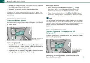
Fig. 16 CHEC K button
in th e instru ment
c lu ster
Driv er information di splay
For example, if the transmission selector lever is not in the P posi
ti on when the engine is turned off, the following message appears:
Shift t o P, otherwi se ve hic le can roll away. Doors do not lo ck if
le ver i s not in P .
The igni tion key can only be removed with the selector in this pos i
tion. This and other messages are brought up if a function cannot
be car ried ou t.
Dri ver messa ges and r ed symbols
If a red symbo l appears in the display, a driver message can be
shown by pressing the [ CH ECK] button.
For example, the symbol f or a problem with engine oi l
pressure~
appears in the disp lay . If you then press the [ CHECK] button , the
fo llowing driver message appears in the d isp lay:
S witch off engine and che ck oil level
The driver message in the display goes out after about 5 seconds .
The dr iver message can be d isplayed aga in by briefly pressing the
[ CHECK] button .
Driver me ssages and yellow symbols
If a yellow symbol appears in the display, a driver message is also
displayed automat ica lly .
For examp le, the symbol
G> appears in the disp lay, indicating low
windshield washer fluid level. The following message also appears :
Please top up wa sher fluid
The driver message disappears after a few seconds . The driver
message can be d isplayed aga in by briefly pressing the [ CHECK]
button. •
Page 32 of 404

Driver inf orma tio n displ ay
Red symbols
A red symbol means DANGER.
Pull off the road.
-Stop the vehicle .
-Turn off the engine.
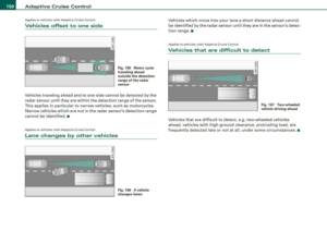
Fig . 17 Dis play: en gine
co ola nt leve l warnin g
(pr iori ty 1)
-Check the malfunctioning system. Contact your aut ho-
rized Audi dea ler or a qua lified workshop for assistance.
Red symbols indicate a prio rity malfunction -Danger!
With a priority 1 malfunction, a large symbol appears in the center area of the
disp lay => fig. 17. When the symbol appears, three
warning tones sound in succession . The symbol continues to blink
until the malfunction has been repaired .
After a few seconds, the large symbol is replaced by a small symbol shown at the top left of the display. This symbol is displayed until
the fault is corrected.
If there are more than one priority 1 malfunctions, the symbo ls
appear one after the other for about 2 seconds .
An additional driver message can a lso be d isplayed by briefly
pressing the
( CHECK) button .
The red symbols mean:
BRAKE
-
((l))
©
.....
[ i ] Tips
U SA m od els: => page 30
Brake system malfunction
C anad a mod els:
B rake system malfunction
II=> page 30
Engine coolant level too
=> page 31
low/engine coolant temperature
too high
En gine o il p ress ure too lo w
=> page 32
Faulty steering
=> page 33
Fa ult y ig nition s witch
=> page 33
• If the warning/indicator light
BRAKE (USA mode ls)/ <@ (Canada
models) in the instrument cluster flashes, there is a brake system
malfunction. By pressing the [
CHECK) button, you can bring up a
driver message which exp lains the malfunction in more detail.
Please
note=> page 30.
• Speed warnings threshold 1
8 (USA modelsl /8 (Canada
models) and threshold 2
8 . (USA models)/ 0, (Canada models) are
also shown as red symbo ls . The warning is a lways shown as a small
symbol in the upper area of the
display => page 36 . •
Brake system malfunction
A malfunction in the brake system must be repaired as
soon as possible.
If the warning /indi cator light BRAKE (USA models)/ ((D)
(Canada models) in the instr ument cluster flashes, there is
a brake system malfunction . By pressing the [
CHECK] ~