Page 2420 of 3000
BRAKE CONTROL – ANTI-LOCK BRAKE SYSTEMBC–59
BC
(b) Measure the resistance according to the value(s) in the
table below.
Standard resistance
NG
OK
(a) Turn the ignition switch off.
(b) Disconnect the combination meter connector.
C119429E03
Tester Connection Specified Condition
C10-13 - B1-1 Below 1
C10-13 - Body ground 10 k or higher
B1-2 - Body ground Below 1
REPAIR OR REPLACE HARNESS OR
CONNECTOR (BRAKE FLUID LEVEL
WARNING SWITCH CIRCUIT)
10CHECK HARNESS AND CONNECTOR (BETWEEN SKID CONTROL ECU AND
COMBINATION METER ASSEMBLY)
Page 2433 of 3000
BRAKE CONTROL – VEHICLE STABILITY CONTROL SYSTEMBC–69
BC
HOW TO PROCEED WITH
TROUBLESHOOTING
The intelligent tester can be used at step 2, 5, 8, 11.
HINT:
See page BC-82 and BC-84.
HINT:
See page BC-82.
HINT:
See page BC-79.
HINT:
See page BC-88.
1Vehicle Brought to Workshop
2Check and Clear DTCs and Freeze Frame Data
3Problem Symptom Confirmation
Symptom does not occur: Go to step 5
Symptom occurs: Go to step 6
4Symptom Simulation
5DTC Check
There is no output: Go to step 7
There is output: Go to step 8
6Problem Symptoms Table
Check for fluid leakage and Go to step 10
7DTC Chart
Page 2437 of 3000

BRAKE CONTROL – VEHICLE STABILITY CONTROL SYSTEMBC–73
BC
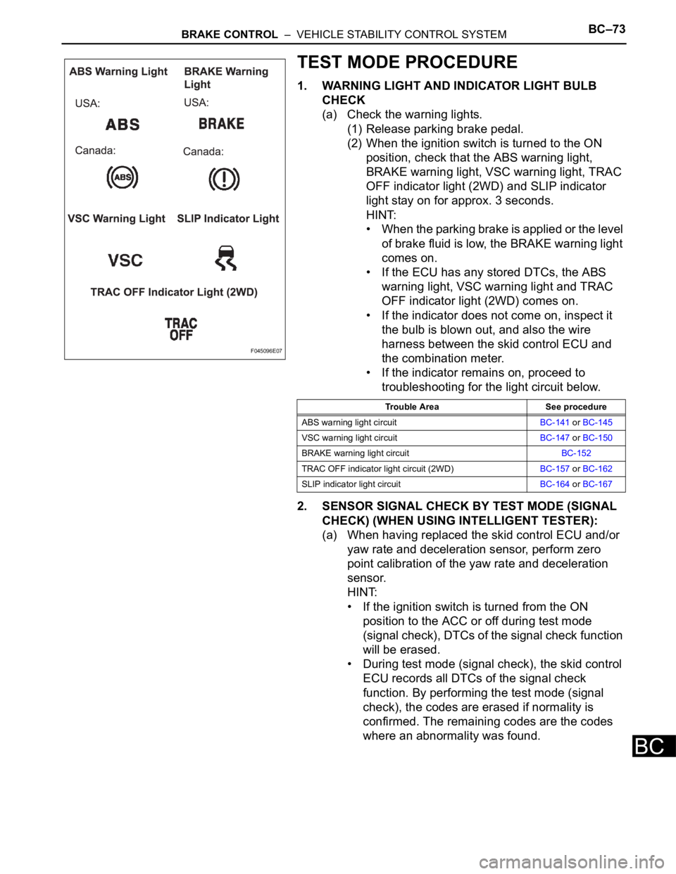
TEST MODE PROCEDURE
1. WARNING LIGHT AND INDICATOR LIGHT BULB
CHECK
(a) Check the warning lights.
(1) Release parking brake pedal.
(2) When the ignition switch is turned to the ON
position, check that the ABS warning light,
BRAKE warning light, VSC warning light, TRAC
OFF indicator light (2WD) and SLIP indicator
light stay on for approx. 3 seconds.
HINT:
• When the parking brake is applied or the level
of brake fluid is low, the BRAKE warning light
comes on.
• If the ECU has any stored DTCs, the ABS
warning light, VSC warning light and TRAC
OFF indicator light (2WD) comes on.
• If the indicator does not come on, inspect it
the bulb is blown out, and also the wire
harness between the skid control ECU and
the combination meter.
• If the indicator remains on, proceed to
troubleshooting for the light circuit below.
2. SENSOR SIGNAL CHECK BY TEST MODE (SIGNAL
CHECK) (WHEN USING INTELLIGENT TESTER):
(a) When having replaced the skid control ECU and/or
yaw rate and deceleration sensor, perform zero
point calibration of the yaw rate and deceleration
sensor.
HINT:
• If the ignition switch is turned from the ON
position to the ACC or off during test mode
(signal check), DTCs of the signal check function
will be erased.
• During test mode (signal check), the skid control
ECU records all DTCs of the signal check
function. By performing the test mode (signal
check), the codes are erased if normality is
confirmed. The remaining codes are the codes
where an abnormality was found.
F045096E07
Trouble Area See procedure
ABS warning light circuitBC-141 or BC-145
VSC warning light circuitBC-147 or BC-150
BRAKE warning light circuitBC-152
TRAC OFF indicator light circuit (2WD)BC-157 or BC-162
SLIP indicator light circuitBC-164 or BC-167
Page 2493 of 3000

BRAKE CONTROL – VEHICLE STABILITY CONTROL SYSTEMBC–131
BC
DESCRIPTION
Master cylinder pressure sensor is connected to the skid control ECU in the actuator.
INSPECTION PROCEDURE
(a) Connect the intelligent tester to the DLC3.
(b) Start the engine.
(c) Select the DATA LIST mode on the intelligent tester.
ABS / VSC:
(d) Check that the brake fluid pressure value of the master
cylinder pressure sensor indicated on the intelligent
tester, changes when the brake pedal is depressed.
OK:
Brake fluid pressure value should change.
NOTICE:
When replacing the brake actuator assembly,
perform zero point calibration (See page BC-70).
NG
OK
DTC C1246/46 Master Cylinder Pressure Sensor Malfunction
DTC Code DTC Detection Condition Trouble Area
C1246/46When any of the following is detected:
1. When the vehicle speed is 7 km/h (4 mph) or more
and PMC terminal voltage of skid control ECU
exceeds 0.86 V, the condition that the voltage does
not change by 0.005 V or more continues for 30
sec.
2. Noise in terminal PMC of skid control ECU occurs 7
times or more within 5 sec.
3. When the stop light switch is off, the condition that
PMC terminal voltage of skid control ECU is 0.86 V
or more, or less than 0.3 V continues for 5 sec. or
more.
4. When IG1 terminal voltage is between 9.5 and 17.2
V, the condition that the VCM terminal voltage of
skid control ECU is out of the range from 4.4 to 5.6
V continues for 1.2 sec. or more.
5. When VCM terminal voltage of skid control ECU is
between 4.4 and 5.6 V, the condition that the PMC
terminal voltage of skid control ECU is out of the
range from 0.14 to 4.85 V continues for 1.2 sec. or
more.• Master cylinder pressure sensor
• Master cylinder pressure sensor circuit
1READ VALUE ON INTELLIGENT TESTER (MASTER CYLINDER PRESSURE SENSOR)
Tester Display Measurement Item/Range Normal Condition
MAS CYL PRS 1Master cylinder pressure sensor 1 reading /
min.: 0 V, max.: 5 VWhen brake pedal is released : 0.3 to 0.9 V
Go to step 2
REPLACE BRAKE ACTUATOR ASSEMBLY
Page 2516 of 3000
BC–154BRAKE CONTROL – VEHICLE STABILITY CONTROL SYSTEM
BC
DESCRIPTION
The BRAKE warning light comes on when the brake fluid is insufficient, the parking brake is applied or the
EBD is defective.
WIRING DIAGRAM
INSPECTION PROCEDURE
HINT:
When releasing the parking brake, move the shift lever into the P position in an AT vehicle, and choke in
an MT vehicle to hold the vehicle for safety.
Brake Warning Light Remains ON
C160966E02
Page 2517 of 3000

BRAKE CONTROL – VEHICLE STABILITY CONTROL SYSTEMBC–155
BC
(a) Check that the brake fluid level is proper.
NG
OK
(a) Are the DTC recorded? (See page BC-82)
Result
B
A
(a) WHEN USING INTELLIGENT TESTER:
(1) Connect the intelligent tester to the DLC3.
(2) Start the engine.
(3) Select the item "BRAKE WARN LIGHT" in the
ACTIVE TEST and operate the BRAKE warning
light on the intelligent tester.
ABS / VSC:
(4) Check that "ON" and "OFF" of the BRAKE warning
light are indicated on the combination meter when
using the intelligent tester.
OK:
Turn the BRAKE warning light on or off in
accordance with the intelligent tester.
(b) WHEN NOT USING INTELLIGENT TESTER:
(1) Turn the ignition switch off and disconnect the
connector from the skid control ECU.
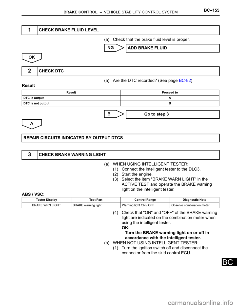
1CHECK BRAKE FLUID LEVEL
ADD BRAKE FLUID
2CHECK DTC
Result Proceed to
DTC is outputA
DTC is not outputB
Go to step 3
REPAIR CIRCUITS INDICATED BY OUTPUT DTCS
3CHECK BRAKE WARNING LIGHT
Tester Display Test Part Control Range Diagnostic Note
BRAKE WRN LIGHT BRAKE warning light Warning light ON / OFF Observe combination meter
Page 2519 of 3000
BRAKE CONTROL – VEHICLE STABILITY CONTROL SYSTEMBC–157
BC
OK
(a) Remove the reservoir tank cap and strainer.
(b) Disconnect the brake fluid level warning switch
connector.
(c) Measure the resistance according to the value(s) in the
table below.
Standard resistance
NG
OK
(a) Disconnect the combination meter connector and the
brake fluid level warning switch connector.
6INSPECT BRAKE FLUID LEVEL WARNING SWITCH
C119428E02
Tester Connection Switch Condition Specified Condition
(B1-1) - (B1-2) Float UP 10 k
or higher
(B1-1) - (B1-2) Float DOWN Below 1
REPLACE BRAKE MASTER CYLINDER
RESERVOIR SUB-ASSEMBLY (BRAKE
FLUID LEVEL WARNING SWITCH)
7CHECK HARNESS AND CONNECTOR (BRAKE FLUID LEVEL WARNING SWITCH -
COMBINATION METER)
Page 2546 of 3000
BC–180BRAKE CONTROL – BRAKE ACTUATOR (w/ VSC)
BC
REMOVAL
1. DRAIN BRAKE FLUID
NOTICE:
Wash brake fluid off immediately if it adheres to any
painted surface.
2. DISCONNECT BATTERY NEGATIVE TERMINAL
3. REMOVE AIR CLEANER ASSEMBLY WITH HOSE
4. REMOVE BRAKE ACTUATOR WITH BRACKET
(a) Release the latch of the brake actuator connector to
disconnect the connector.
(b) Using SST, disconnect the 6 brake tubes from the
actuator with bracket.
SST 09023-00101
(c) Use tags or make a memo to identify the places to
reconnect.
(d) Remove the 3 bolts and the actuator with bracket.
NOTICE:
Be careful not to damage the brake tubes and
wire harness.
5. REMOVE BRAKE ACTUATOR
(a) Remove the 2 nuts and the brake actuator assembly
from the brake actuator bracket.
G024309
F045511E01
G024308