2007 TOYOTA SIENNA throttle position
[x] Cancel search: throttle positionPage 465 of 3000
2GR-FE ENGINE CONTROL SYSTEM – SFI SYSTEMES–159
ES
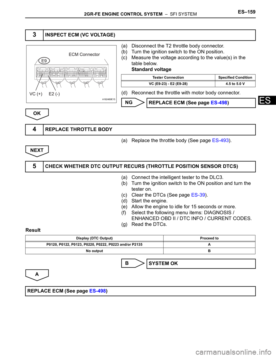
(a) Disconnect the T2 throttle body connector.
(b) Turn the ignition switch to the ON position.
(c) Measure the voltage according to the value(s) in the
table below.
Standard voltage
(d) Reconnect the throttle with motor body connector.
NG
OK
(a) Replace the throttle body (See page ES-493).
NEXT
(a) Connect the intelligent tester to the DLC3.
(b) Turn the ignition switch to the ON position and turn the
tester on.
(c) Clear the DTCs (See page ES-39).
(d) Start the engine.
(e) Allow the engine to idle for 15 seconds or more.
(f) Select the following menu items: DIAGNOSIS /
ENHANCED OBD II / DTC INFO / CURRENT CODES.
(g) Read the DTCs.
Result
B
A
3INSPECT ECM (VC VOLTAGE)
A162489E15
Tester Connection Specified Condition
VC (E9-23) - E2 (E9-28) 4.5 to 5.0 V
REPLACE ECM (See page ES-498)
4REPLACE THROTTLE BODY
5CHECK WHETHER DTC OUTPUT RECURS (THROTTLE POSITION SENSOR DTCS)
Display (DTC Output) Proceed to
P0120, P0122, P0123, P0220, P0222, P0223 and/or P2135 A
No output B
SYSTEM OK
REPLACE ECM (See page ES-498)
Page 466 of 3000

ES–1602GR-FE ENGINE CONTROL SYSTEM – SFI SYSTEM
ES
HINT:
This DTC relates to the Throttle Position (TP) sensor.
DESCRIPTION
Refer to DTC P0120 (See page ES-145).
MONITOR DESCRIPTION
The ECM uses the TP sensor to monitor the throttle valve opening angle.
This sensor transmits two signals: VTA1 and VTA2. VTA1 is used to detect the throttle opening angle and
VTA2 is used to detect malfunctions in VTA1. The ECM performs several checks to confirm the proper
operation of the TP sensor and VTA1.
For each throttle opening angle, a specific voltage difference is expected between the outputs of VTA1
and VTA2. If the voltage output difference between the two signals deviates from the normal operating
range, the ECM interprets this as a malfunction of the TP sensor. The ECM illuminates the MIL and sets
the DTC.
If the malfunction is not repaired successfully, the DTC is set 2 seconds after the engine is next started.
MONITOR STRATEGY
TYPICAL ENABLING CONDITIONS
TYPICAL MALFUNCTION THRESHOLDS
DTC P0121Throttle / Pedal Position Sensor / Switch "A"
Circuit Range / Performance Problem
DTC No. DTC Detection Condition Trouble Area
P0121Difference between VTA1 and VTA2 voltages less than
0.8 V, or more than 1.6 V for 2 seconds (1 trip detection
logic)TP sensor (built into throttle body)
Related DTCs P0121: TP sensor rationality
Required Sensors / Components (Main) TP sensor
Required Sensors / Components (Related) -
Frequency of Operation Continuous
Duration Within 2 seconds
MIL Operation Immediate
Sequence of Operation None
This monitor will not run whenever these DTCs are not
presentNone
Either of the following conditions is met: Condition 1 or 2
1. Ignition switch ON
2. Electric throttle motor power ON
TP sensor malfunction (P0120, P0122, P0123, P0220,
P0222, P0223, P2135)Not detected
Difference of TP sensor voltage between VTA1 and
VTA2 x 0.8Less than 0.8 V, or more than 1.6 V
Page 467 of 3000

2GR-FE ENGINE CONTROL SYSTEM – SFI SYSTEMES–161
ES
FAIL-SAFE
When this DTC, as well as other DTCs relating to ETCS (Electronic Throttle Control System)
malfunctions, is set, the ECM enters fail-safe mode. During fail-safe mode, the ECM cuts the current to
the throttle actuator off, and the throttle valve is returned to a 6.5
throttle angle by the return spring. The
ECM then adjusts the engine output by controlling the fuel injection (intermittent fuel-cut) and ignition
timing, in accordance with the accelerator pedal opening angle, to allow the vehicle to continue at a
minimal speed. If the accelerator pedal is depressed slowly, the vehicle can be driven slowly.
Fail-safe mode continues until a pass condition is detected, and the ignition switch is then turned off.
INSPECTION PROCEDURE
HINT:
Read freeze frame data using the intelligent tester. The ECM records vehicle and driving condition
information as freeze frame data the moment a DTC is stored. When troubleshooting, freeze frame data
can be helpful in determining whether the vehicle was running or stopped, whether the engine was
warmed up or not, whether the air-fuel ratio was lean or rich, as well as other data recorded at the time of
a malfunction.
(a) Connect the intelligent tester to the DLC3.
(b) Turn the ignition switch to the ON position.
(c) Turn the tester ON.
(d) Enter the following menus: DIAGNOSIS / ENHANCED
OBD II / DTC INFO / CURRENT CODES.
(e) Read the DTC.
Result
HINT:
If any DTCs other than P0121 are output, troubleshoot
those DTCs first.
B
A
1CHECK ANY OTHER DTC OUTPUT (IN ADDITION TO DTC P0121)
Display (DTC output) Proceed to
P0121 A
P0121 and other DTCs B
GO TO DTC CHART
REPLACE THROTTLE BODY
Page 478 of 3000
ES–1722GR-FE ENGINE CONTROL SYSTEM – SFI SYSTEM
ES
High or Low Impedance of Heated Oxygen (HO2) Sensor (DTCs P0136 and P0156 or P0137 and
P0157)
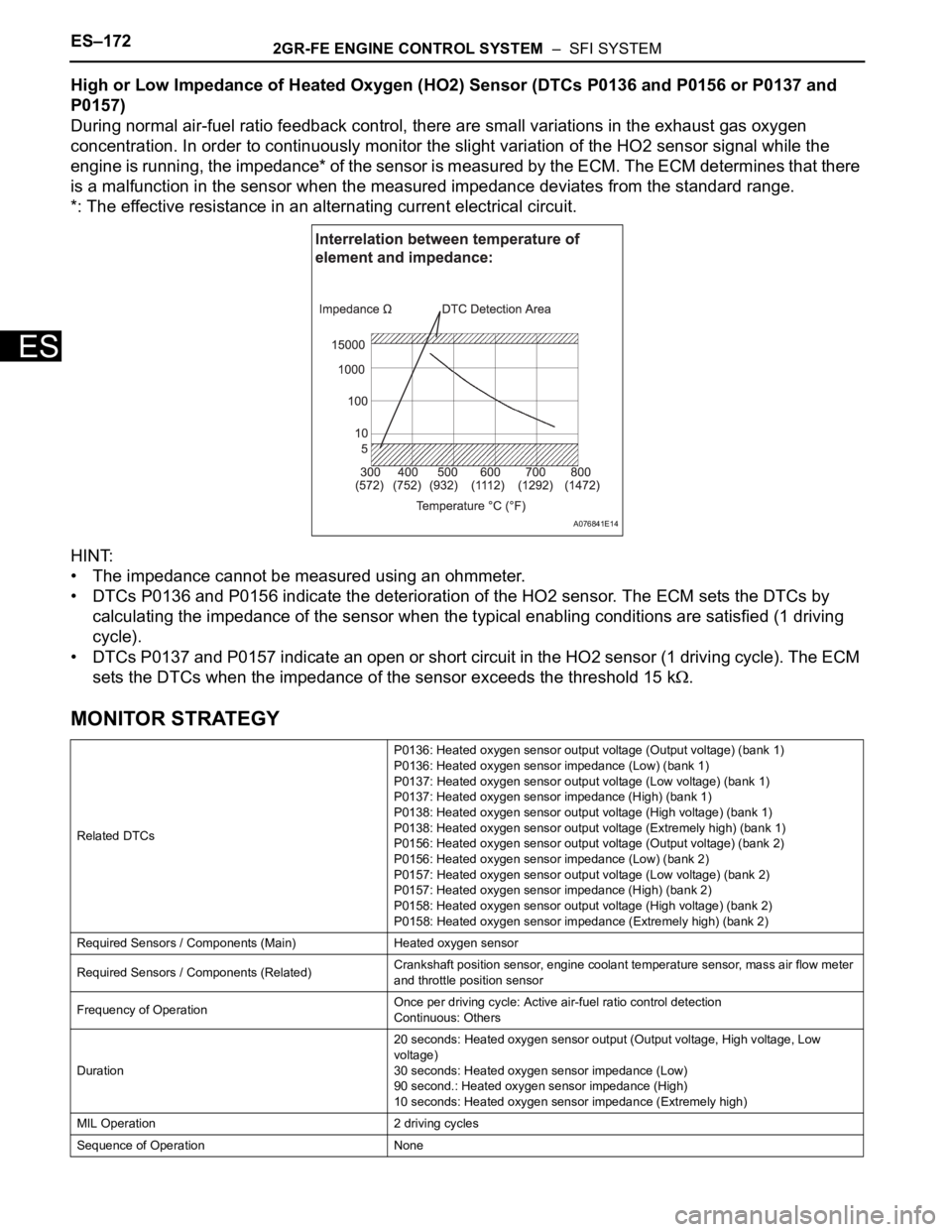
During normal air-fuel ratio feedback control, there are small variations in the exhaust gas oxygen
concentration. In order to continuously monitor the slight variation of the HO2 sensor signal while the
engine is running, the impedance* of the sensor is measured by the ECM. The ECM determines that there
is a malfunction in the sensor when the measured impedance deviates from the standard range.
*: The effective resistance in an alternating current electrical circuit.
HINT:
• The impedance cannot be measured using an ohmmeter.
• DTCs P0136 and P0156 indicate the deterioration of the HO2 sensor. The ECM sets the DTCs by
calculating the impedance of the sensor when the typical enabling conditions are satisfied (1 driving
cycle).
• DTCs P0137 and P0157 indicate an open or short circuit in the HO2 sensor (1 driving cycle). The ECM
sets the DTCs when the impedance of the sensor exceeds the threshold 15 k
.
MONITOR STRATEGY
Related DTCsP0136: Heated oxygen sensor output voltage (Output voltage) (bank 1)
P0136: Heated oxygen sensor impedance (Low) (bank 1)
P0137: Heated oxygen sensor output voltage (Low voltage) (bank 1)
P0137: Heated oxygen sensor impedance (High) (bank 1)
P0138: Heated oxygen sensor output voltage (High voltage) (bank 1)
P0138: Heated oxygen sensor output voltage (Extremely high) (bank 1)
P0156: Heated oxygen sensor output voltage (Output voltage) (bank 2)
P0156: Heated oxygen sensor impedance (Low) (bank 2)
P0157: Heated oxygen sensor output voltage (Low voltage) (bank 2)
P0157: Heated oxygen sensor impedance (High) (bank 2)
P0158: Heated oxygen sensor output voltage (High voltage) (bank 2)
P0158: Heated oxygen sensor impedance (Extremely high) (bank 2)
Required Sensors / Components (Main) Heated oxygen sensor
Required Sensors / Components (Related)Crankshaft position sensor, engine coolant temperature sensor, mass air flow meter
and throttle position sensor
Frequency of OperationOnce per driving cycle: Active air-fuel ratio control detection
Continuous: Others
Duration20 seconds: Heated oxygen sensor output (Output voltage, High voltage, Low
voltage)
30 seconds: Heated oxygen sensor impedance (Low)
90 second.: Heated oxygen sensor impedance (High)
10 seconds: Heated oxygen sensor impedance (Extremely high)
MIL Operation 2 driving cycles
Sequence of Operation None
A076841E14
Page 593 of 3000

ES–3002GR-FE ENGINE CONTROL SYSTEM – SFI SYSTEM
ES
DESCRIPTION
The idling speed is controlled by the ETCS (Electronic Throttle Control System). The ETCS is comprised
of: 1) the one valve type throttle body; 2) the throttle actuator, which operates the throttle valve; 3) the
Throttle Position (TP) sensor, which detects the opening angle of the throttle valve; 4) the Accelerator
Pedal Position (APP) sensor, which detects the accelerator pedal position; and 5) the ECM, which
controls the ETCS.
Based on the target idling speed, the ECM controls the throttle actuator to provide the proper throttle valve
opening angle.
MONITOR DESCRIPTION
The ECM monitors the idling speed and idling air flow volume to conduct Idle Speed Control (ISC). The
ECM determines that the ISC system is malfunctioning if the following conditions are met:
• The learned idling air flow volume remains at the maximum or minimum volume 5 times or more in a
drive cycle.
• While driving at 6 mph (10 km/h) or more, the actual engine idling speed varies from the target idling
speed by between 100 rpm and 200 rpm, 5 times or more in a drive cycle.
DTC P0505 Idle Control System Malfunction
DTC No. DTC Detection Condition Trouble Area
P0505Idling speed continues to vary greatly from target idling
speed (2 trip detection logic)•ETCS
• Intake system
• PCV hose connection
•ECM
Page 595 of 3000
ES–3022GR-FE ENGINE CONTROL SYSTEM – SFI SYSTEM
ES
INSPECTION PROCEDURE
HINT:
• The following conditions may also cause DTC P0505 to be set:
(a) The floor carpet overlapping slightly onto the accelerator pedal, causing the accelerator pedal to be
slightly depressed and therefore the throttle valve position to be slightly open.
(b) The accelerator pedal being not fully released.
• Read freeze frame data using the intelligent tester. The ECM records vehicle and driving condition
information as freeze frame data the moment a DTC is stored. When troubleshooting, freeze frame
data can be helpful in determining whether the vehicle was running or stopped, whether the engine
was warmed up or not, whether the air-fuel ratio was lean or rich, as well as other data recorded at the
time of a malfunction.
(a) Connect the intelligent tester to the DLC3.
(b) Turn the ignition switch to the ON position.
(c) Turn the tester on.
(d) Select the following menu items: DIAGNOSIS /
ENHANCED OBD II / DTC INFO / CURRENT CODES.
(e) Read the DTCs.
Result
HINT:
If any DTCs other than P0505 are output, troubleshoot
those DTCs first.
B
A
OK:
PCV hose is connected correctly and is not damaged.
NG
OK
(a) Check the intake system for vacuum leakage.
(a) Engine RPM - target engine RPM Below -100 rpm, or 150 rpm or more
(b) Vehicle condition Stop after vehicle was driven by 6.25 mph (10.06 km/h) or more
2. Frequency that both of the following conditions (a)
and (b) are metOnce
(a) Engine RPM - target engine RPM Below -100 rpm, or 150 rpm or more
(b) IAC flow rate learning valve 1.3 L/sec. or less, or 8.5 L/sec. or more
1CHECK ANY OTHER DTCS OUTPUT (IN ADDITION TO DTC P0505)
Display (DTC Output) Proceed to
P0505 A
P0505 and other DTCs B
GO TO DTC CHART (See page ES-56)
2CHECK PCV HOSE CONNECTIONS
REPAIR OR REPLACE PCV HOSE
3CHECK INTAKE SYSTEM
Page 598 of 3000
2GR-FE ENGINE CONTROL SYSTEM – SFI SYSTEMES–305
ES
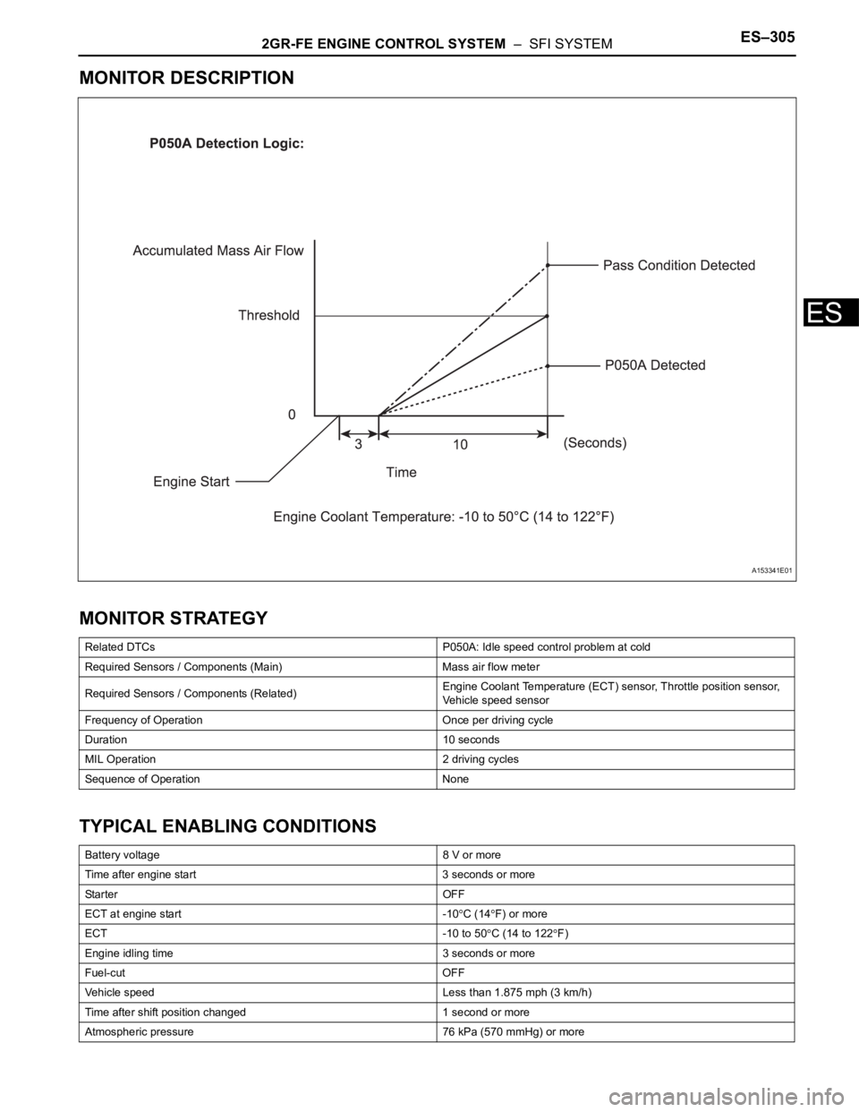
MONITOR DESCRIPTION
MONITOR STRATEGY
TYPICAL ENABLING CONDITIONS
Related DTCs P050A: Idle speed control problem at cold
Required Sensors / Components (Main) Mass air flow meter
Required Sensors / Components (Related)Engine Coolant Temperature (ECT) sensor, Throttle position sensor,
Vehicle speed sensor
Frequency of Operation Once per driving cycle
Duration 10 seconds
MIL Operation 2 driving cycles
Sequence of Operation None
Battery voltage 8 V or more
Time after engine start 3 seconds or more
Sta r t e r OF F
ECT at engine start -10
C (14F) or more
ECT -10 to 50
C (14 to 122F)
Engine idling time 3 seconds or more
Fuel-cut OFF
Vehicle speed Less than 1.875 mph (3 km/h)
Time after shift position changed 1 second or more
Atmospheric pressure 76 kPa (570 mmHg) or more
A153341E01
Page 604 of 3000
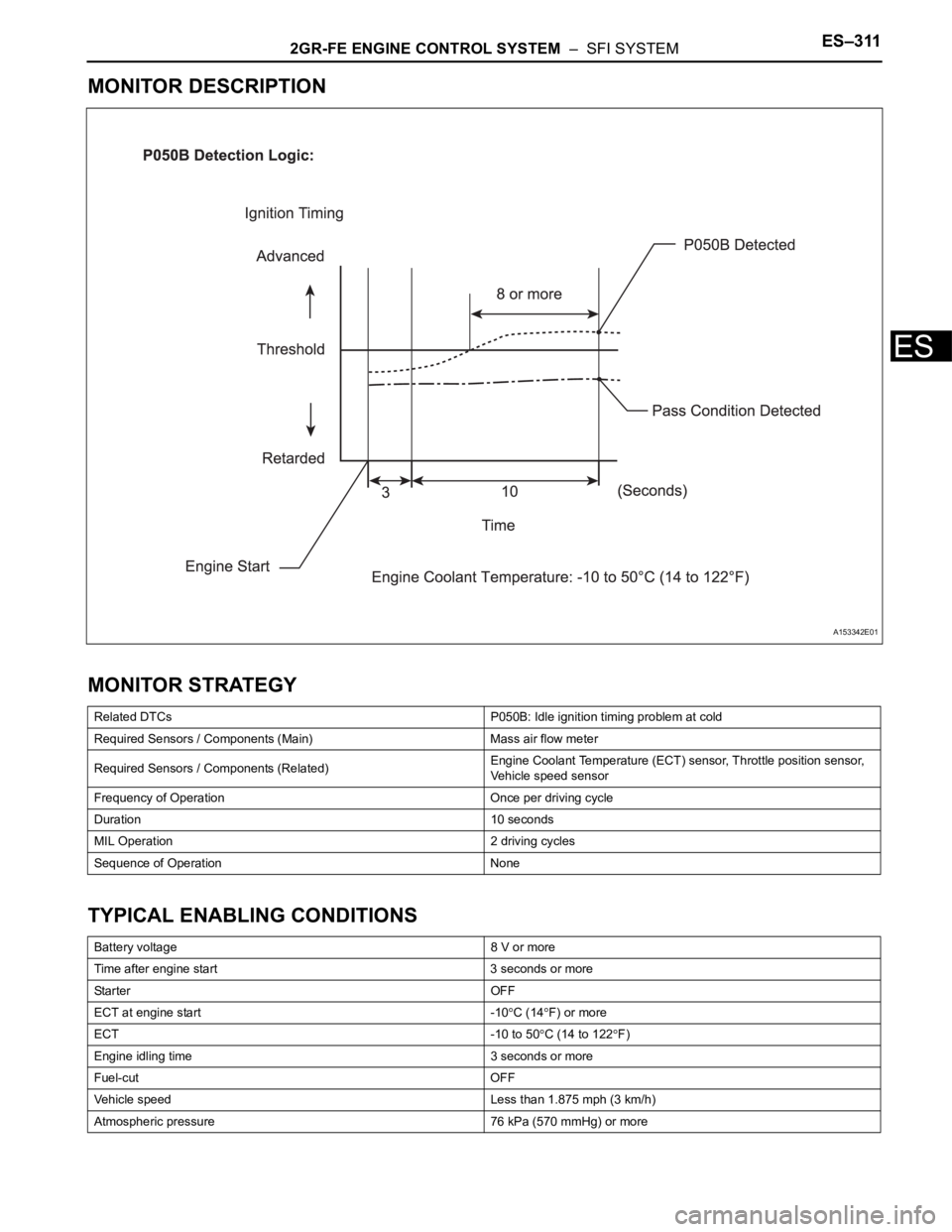
2GR-FE ENGINE CONTROL SYSTEM – SFI SYSTEMES–311
ES
MONITOR DESCRIPTION
MONITOR STRATEGY
TYPICAL ENABLING CONDITIONS
Related DTCs P050B: Idle ignition timing problem at cold
Required Sensors / Components (Main) Mass air flow meter
Required Sensors / Components (Related)Engine Coolant Temperature (ECT) sensor, Throttle position sensor,
Vehicle speed sensor
Frequency of Operation Once per driving cycle
Duration 10 seconds
MIL Operation 2 driving cycles
Sequence of Operation None
Battery voltage 8 V or more
Time after engine start 3 seconds or more
Sta r t e r OF F
ECT at engine start -10
C (14F) or more
ECT -10 to 50
C (14 to 122F)
Engine idling time 3 seconds or more
Fuel-cut OFF
Vehicle speed Less than 1.875 mph (3 km/h)
Atmospheric pressure 76 kPa (570 mmHg) or more
A153342E01