Page 2904 of 3000
AIR CONDITIONING – AIR CONDITIONING SYSTEM (for Automatic Air Conditioning Sys-
tem)AC–15
AC
NOTICE:
*: Before measuring the resistance, leave the
vehicle as is for at least 1 minute and do not
operate the ignition switch, any other switches
or the doors.
DTC CHECK / CLEAR
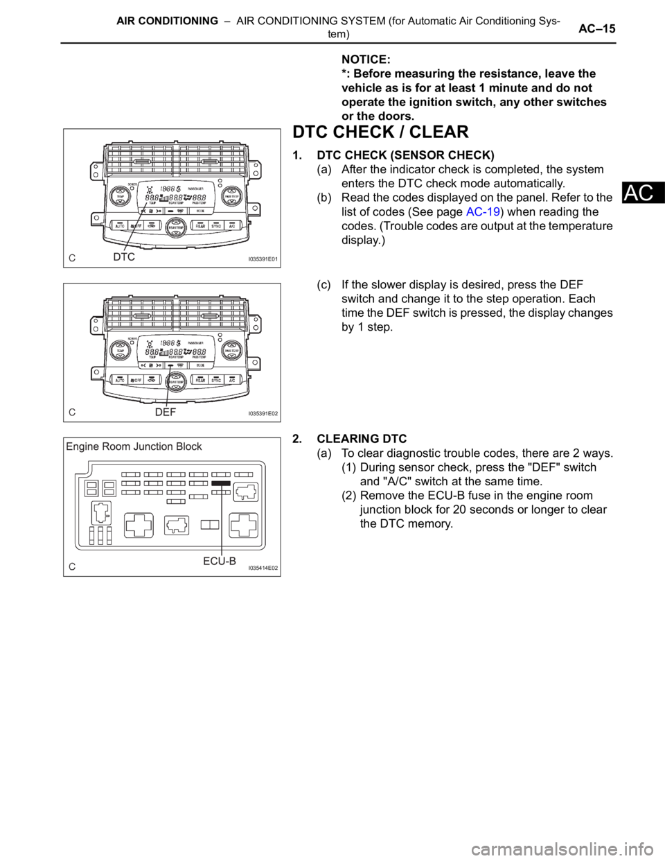
1. DTC CHECK (SENSOR CHECK)
(a) After the indicator check is completed, the system
enters the DTC check mode automatically.
(b) Read the codes displayed on the panel. Refer to the
list of codes (See page AC-19) when reading the
codes. (Trouble codes are output at the temperature
display.)
(c) If the slower display is desired, press the DEF
switch and change it to the step operation. Each
time the DEF switch is pressed, the display changes
by 1 step.
2. CLEARING DTC
(a) To clear diagnostic trouble codes, there are 2 ways.
(1) During sensor check, press the "DEF" switch
and "A/C" switch at the same time.
(2) Remove the ECU-B fuse in the engine room
junction block for 20 seconds or longer to clear
the DTC memory.
I035391E01
I035391E02
I035414E02
Page 2992 of 3000

SUPPLEMENTAL RESTRAINT SYSTEM – AIRBAG SYSTEMRS–15
RS
SYSTEM DESCRIPTION
1. GENERAL
(a) In conjunction with impact absorbing structure for a
frontal collision, the SRS (Supplemental Restraint
System) driver airbag and front passenger airbag
were designed to supplement seat belts in the event
of a frontal collision in order to help reduce shock to
the head and chest. This system is a 3-sensor type
airbag system to detect the impact during a frontal
collision using the center airbag sensor assembly
and front airbag sensors. It also operates the airbag
system and seat belt pretensioner.
(b) In order to detect the extent of the collision during
the initial stages of the collision in further detail, the
front airbag sensors have been changed from
mechanical type to electrical type deceleration
sensors. Accordingly, the deployment of the driver
airbag and front passenger airbag is controlled in
two stages according to the severity of the impact.
(c) In conjunction with impact absorbing structure for a
side collision, the front seat side airbag and curtain
shield airbag were designed to help reduce shock to
the driver, front passenger, and rear outer
passengers in the event of a side collision or
rollover.
(d) RSCA (Roll Sensing of Curtain Shield Airbags) is
used in order to deploy the curtain shield airbags
and the seat belt pretensioner for the driver and
front passenger, in the event that the vehicle rolls
over.
(e) The curtain shield airbag that helps reduce shock to
the front and rear seat occupants with a single
curtain shield airbag has been adopted. In
conjunction with this system, the side airbag
sensors have been installed at the bottom of the
center pillars and the rear airbag sensors have been
installed at the bottom of the rear pillars
respectively.
(f) In this system, a front side collision is detected by
the side airbag sensors in order to deploy the front
seat side airbag and curtain shield airbag. A rear
side collision is detected by the rear airbag sensors
and the center airbag sensor assembly in order to
deploy the curtain shield airbag.
(g) The center airbag sensor assembly sends the
airbag deployment signal to the ECM through BEAN
(Body Electronics Area Network) and CAN
(Controller Area Network) to operate the fuel pump
control.
(h) The center airbag sensor assembly sends the
airbag deployment signal to the body ECU via a
discrete line to operate collision door lock release
control.
Page 2994 of 3000

SUPPLEMENTAL RESTRAINT SYSTEM – AIRBAG SYSTEMRS–17
RS
• The center airbag sensor assembly receives
signals from the deceleration sensor and the
safing sensor built into the center airbag
sensor assembly and the side airbag sensor
and the rear airbag sensor, and determines
whether or not the front seat side airbag and
curtain shield airbag assemblies should be
activated, and diagnoses system
malfunctions.
• The center airbag sensor assembly sends the
airbag deployment signal to the ECM through
BEAN and CAN to operate fuel pump control.
• The center airbag sensor assembly sends the
airbag deployment signal to the main body
ECU through a discrete line to operate
collision door lock release control.
(2) Deceleration sensor and ignition control circuit
• The deceleration sensor is built into the
center airbag sensor assembly, front airbag
sensor, side airbag sensor and rear airbag
sensor, and the distortion created based on
the deceleration of the vehicle during a
frontal, front side or rear side collision is
converted into an electric signal.
• The ignition control circuit performs
calculations based on the signal output from
the deceleration sensors of the center airbag
sensor assembly, front airbag sensor, side
airbag sensor and rear airbag sensor. If the
calculated values are greater than the
specified values, it activates an ignition
operation.
(3) Safing sensor
• The safing sensor is built into the center
airbag sensor assembly. During a frontal
collision, the sensor turns on and outputs an
ON signal to the center airbag sensor
assembly if a deceleration rate greater than
the specified value is applied to the safing
sensor.
(4) Backup power source
• The backup power source consists of a
power supply capacitor and a DC-DC
converter. If the power system does not
function during a collision, the power supply
capacitor discharges and supplies electric
power to the system. The DC-DC converter
operates as a boosting transformer when the
battery voltage falls below a predetermined
level.
Page:
< prev 1-8 9-16 17-24