Page 582 of 3000

2GR-FE ENGINE CONTROL SYSTEM – SFI SYSTEMES–289
ES
Key-off monitor sequence 1 to 8
1. Atmospheric pressure measurement
2. First reference pressure measurement
3. EVAP canister vent valve close stuck check
4. Vacuum introduction
5. EVAP canister purge valve close stuck check
6. Second reference pressure measurement
7. Leak check
8. Atmospheric pressure measurement
TYPICAL MALFUNCTION THRESHOLDS
P0455: EVAP gross leak
P0456: EVAP 0.02 inch leak
2. EVAP purge operation Performed
ECT 4.4 to 35
C (40 to 95F)
IAT 4.4 to 35
C (40 to 95F)
Next sequence is run if the following condition is met -
Atmospheric pressure change Less than 0.3 kPa (2.25 mmHg) in 1 second
Next sequence is run if the following conditions are met Conditions 1, 2 and 3
1. EVAP pressure just after reference pressure
measurement-1 kPa (-7.5 mmHg) or less
2. Reference pressure -4.85 to -1.057 kPa (-36.384 to -7.929 mmHg)
3. Reference pressure Saturated within 1 minutes
Next sequence is run if the following condition is met -
EVAP pressure change after vent valve is ON 0.3 kPa (2.25 mmHg) or more
Next sequence is run if the following condition is met -
EVAP pressure Saturated within 15 minutes
Next sequence is run if the following condition is met -
EVAP pressure change after purge valve is open 0.3 kPa (2.25 mmHg) or more
Next sequence is run if the following conditions are met Conditions 1, 2, 3 and 4
1. EVAP pressure just after reference pressure
measurement-1 kPa (-7.5 mmHg) or less
2. Reference pressure -4.85 to -1.057 kPa (-36.384 to -7.929 mmHg)
3. Reference pressure Saturated
4. Difference between first reference pressure and
second reference pressureLess than 0.7 kPa (5.25 mmHg)
Next sequence is run if the following condition is met -
EVAP pressure when vacuum introduction was
completeLower than second reference pressure
EVAP monitor is complete if the following condition was
met-
Atmospheric pressure difference between sequence 1
and 8Within 0.3 kPa (2.25 mmHg)
EVAP pressure when vacuum introduction is complete Between reference pressure and reference pressure x 0.2
EVAP pressure when vacuum introduction is complete Higher than reference pressure x 0.2
Page 583 of 3000
ES–2902GR-FE ENGINE CONTROL SYSTEM – SFI SYSTEM
ES
MONITOR RESULT
Refer to CHECKING MONITOR STATUS (See page ES-19).
Page 586 of 3000

2GR-FE ENGINE CONTROL SYSTEM – SFI SYSTEMES–293
ES
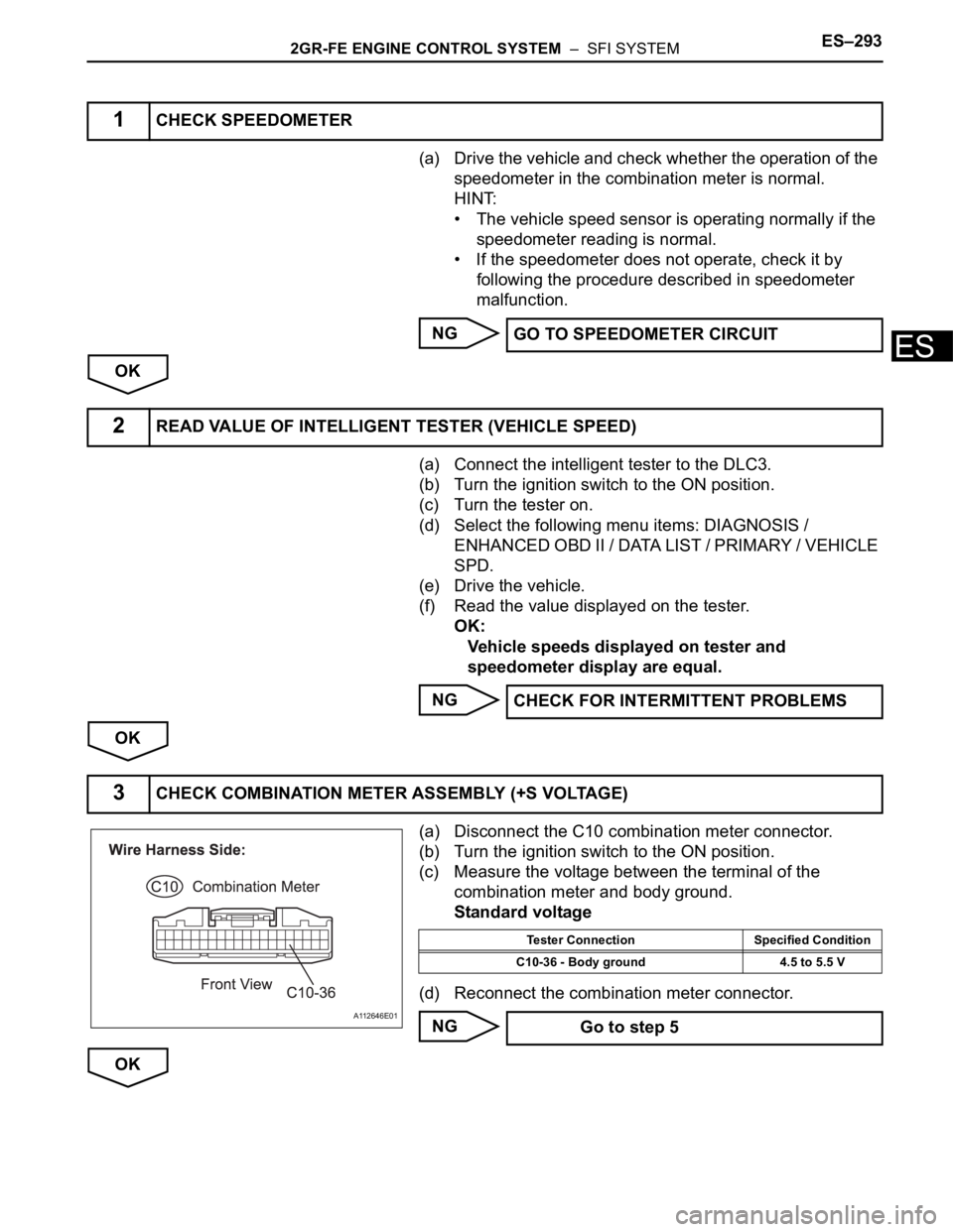
(a) Drive the vehicle and check whether the operation of the
speedometer in the combination meter is normal.
HINT:
• The vehicle speed sensor is operating normally if the
speedometer reading is normal.
• If the speedometer does not operate, check it by
following the procedure described in speedometer
malfunction.
NG
OK
(a) Connect the intelligent tester to the DLC3.
(b) Turn the ignition switch to the ON position.
(c) Turn the tester on.
(d) Select the following menu items: DIAGNOSIS /
ENHANCED OBD II / DATA LIST / PRIMARY / VEHICLE
SPD.
(e) Drive the vehicle.
(f) Read the value displayed on the tester.
OK:
Vehicle speeds displayed on tester and
speedometer display are equal.
NG
OK
(a) Disconnect the C10 combination meter connector.
(b) Turn the ignition switch to the ON position.
(c) Measure the voltage between the terminal of the
combination meter and body ground.
Standard voltage
(d) Reconnect the combination meter connector.
NG
OK
1CHECK SPEEDOMETER
GO TO SPEEDOMETER CIRCUIT
2READ VALUE OF INTELLIGENT TESTER (VEHICLE SPEED)
CHECK FOR INTERMITTENT PROBLEMS
3CHECK COMBINATION METER ASSEMBLY (+S VOLTAGE)
A112646E01
Tester Connection Specified Condition
C10-36 - Body ground 4.5 to 5.5 V
Go to step 5
Page 587 of 3000
ES–2942GR-FE ENGINE CONTROL SYSTEM – SFI SYSTEM
ES
(a) Shift the transmission gear selector lever to the neutral
position.
(b) Jack up the vehicle.
(c) Turn the ignition switch to the ON position.
(d) Measure the voltage between the terminal of the
combination meter and body ground while the wheel is
turned slowly.
Standard voltage
HINT:
The output voltage should fluctuate up and down,
similarly to the diagram, when the wheel is turned slowly.
NG
OK
4CHECK COMBINATION METER ASSEMBLY (SPD SIGNAL WAVEFORM)
I034622E02
A062954E06
Tester Connection Specified Condition
C10-36 - Body ground Voltage generated intermittently
REPLACE COMBINATION METER
ASSEMBLY
Page 588 of 3000
2GR-FE ENGINE CONTROL SYSTEM – SFI SYSTEMES–295
ES
(a) Disconnect the C10 combination meter connector.
(b) Disconnect the E5 ECM connector.
(c) Measure the resistance.
Standard resistance (Check for open)
Standard resistance (Check for short)
(d) Reconnect the combination meter connector.
(e) Reconnect the ECM connector.
NG
OK
5CHECK HARNESS AND CONNECTOR (COMBINATION METER ASSEMBLY - ECM)
A163122E01
Tester Connection Specified Condition
C10-36 - SPD (E5-8) Below 1
Tester Connection Specified Condition
C10-36 or SPD (E5-8) - Body ground 10 k
or higher
REPAIR OR REPLACE HARNESS OR
CONNECTOR (COMBINATION METER
ASSEMBLY - ECM)
REPLACE ECM (See page ES-498)
Page 590 of 3000
2GR-FE ENGINE CONTROL SYSTEM – SFI SYSTEMES–297
ES
TYPICAL MALFUNCTION THRESHOLDS
WIRING DIAGRAM
INSPECTION PROCEDURE
HINT:
Read freeze frame data using the intelligent tester. The ECM records vehicle and driving condition
information as freeze frame data the moment a DTC is stored. When troubleshooting, freeze frame data
can be helpful in determining whether the vehicle was running or stopped, whether the engine was
warmed up or not, whether the air-fuel ratio was lean or rich, as well as other data recorded at the time of
a malfunction.
(a) Check whether the stop lights turn on and off normally
when the brake pedal is depressed and released.
OK:
Stop lights turn on when brake pedal is depressed.
NG
OK
Switch status ON stuck Remain ON during GO and STOP 5 times
1CHECK OPERATION OF STOP LIGHT
A162496E02
GO TO TAILLIGHT RELAY CIRCUIT (See
page LI-114)
Page 591 of 3000

ES–2982GR-FE ENGINE CONTROL SYSTEM – SFI SYSTEM
ES
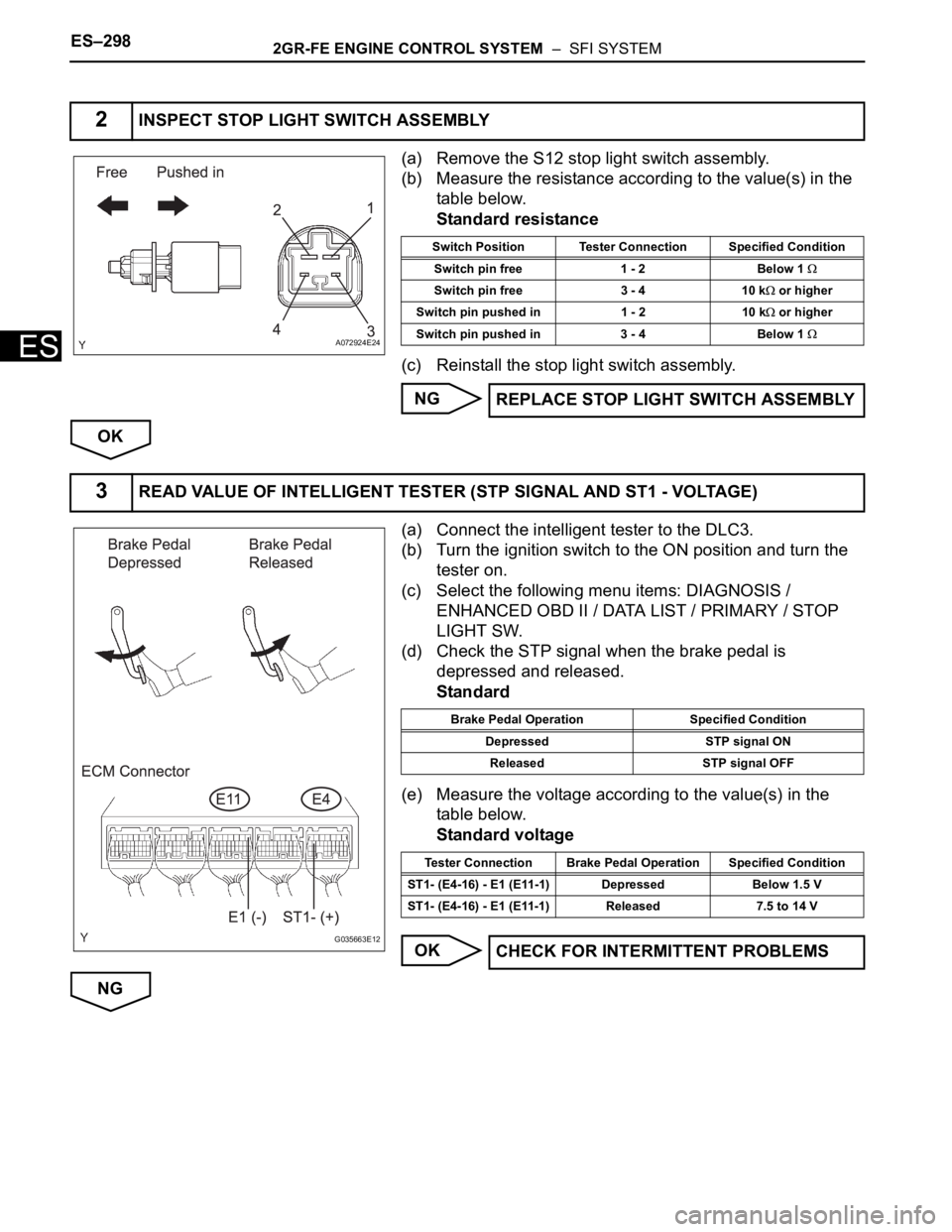
(a) Remove the S12 stop light switch assembly.
(b) Measure the resistance according to the value(s) in the
table below.
Standard resistance
(c) Reinstall the stop light switch assembly.
NG
OK
(a) Connect the intelligent tester to the DLC3.
(b) Turn the ignition switch to the ON position and turn the
tester on.
(c) Select the following menu items: DIAGNOSIS /
ENHANCED OBD II / DATA LIST / PRIMARY / STOP
LIGHT SW.
(d) Check the STP signal when the brake pedal is
depressed and released.
Standard
(e) Measure the voltage according to the value(s) in the
table below.
Standard voltage
OK
NG
2INSPECT STOP LIGHT SWITCH ASSEMBLY
A072924E24
Switch Position Tester Connection Specified Condition
Switch pin free 1 - 2 Below 1
Switch pin free 3 - 4 10 k or higher
Switch pin pushed in 1 - 2 10 k
or higher
Switch pin pushed in 3 - 4 Below 1
REPLACE STOP LIGHT SWITCH ASSEMBLY
3READ VALUE OF INTELLIGENT TESTER (STP SIGNAL AND ST1 - VOLTAGE)
G035663E12
Brake Pedal Operation Specified Condition
Depressed STP signal ON
Released STP signal OFF
Tester Connection Brake Pedal Operation Specified Condition
ST1- (E4-16) - E1 (E11-1) Depressed Below 1.5 V
ST1- (E4-16) - E1 (E11-1) Released 7.5 to 14 V
CHECK FOR INTERMITTENT PROBLEMS
Page 592 of 3000
2GR-FE ENGINE CONTROL SYSTEM – SFI SYSTEMES–299
ES
(a) Disconnect the S12 stop light switch connector.
(b) Disconnect the E4 ECM connector.
(c) Measure the resistance according to the value(s) in the
table below.
Standard resistance :
Check for open
Check for short
(d) Reconnect the stop light switch connector.
(e) Reconnect the ECM connector.
NG
OK
4CHECK HARNESS AND CONNECTOR (STOP LIGHT SWITCH - ECM)
A114629E09
Tester Connection Specified Condition
Stop light switch (S12-1) - STP (E4-15) Below 1
Stop light switch (S12-4) - ST1- (E4-16) Below 1
Tester Connection Specified Condition
Stop light switch (S12-1) or STP (E4-15) - Body
ground10 k
or higher
Stop light switch (S12-4) or ST1- (E4-16) - Body
ground10 k
or higher
REPAIR OR REPLACE HARNESS OR
CONNECTOR (STOP LIGHT SWITCH - ECM)
REPLACE ECM (See page ES-498)