Page 183 of 3000
BRAKE CONTROL – ANTI-LOCK BRAKE SYSTEMBC–7
BC
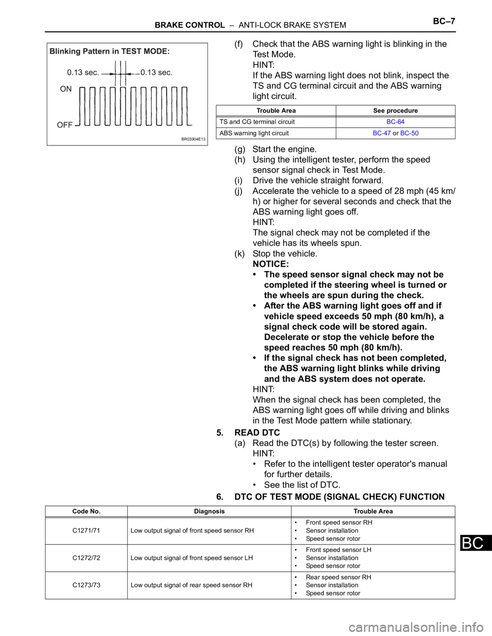
(f) Check that the ABS warning light is blinking in the
Test Mode.
HINT:
If the ABS warning light does not blink, inspect the
TS and CG terminal circuit and the ABS warning
light circuit.
(g) Start the engine.
(h) Using the intelligent tester, perform the speed
sensor signal check in Test Mode.
(i) Drive the vehicle straight forward.
(j) Accelerate the vehicle to a speed of 28 mph (45 km/
h) or higher for several seconds and check that the
ABS warning light goes off.
HINT:
The signal check may not be completed if the
vehicle has its wheels spun.
(k) Stop the vehicle.
NOTICE:
• The speed sensor signal check may not be
completed if the steering wheel is turned or
the wheels are spun during the check.
• After the ABS warning light goes off and if
vehicle speed exceeds 50 mph (80 km/h), a
signal check code will be stored again.
Decelerate or stop the vehicle before the
speed reaches 50 mph (80 km/h).
• If the signal check has not been completed,
the ABS warning light blinks while driving
and the ABS system does not operate.
HINT:
When the signal check has been completed, the
ABS warning light goes off while driving and blinks
in the Test Mode pattern while stationary.
5. READ DTC
(a) Read the DTC(s) by following the tester screen.
HINT:
• Refer to the intelligent tester operator's manual
for further details.
• See the list of DTC.
6. DTC OF TEST MODE (SIGNAL CHECK) FUNCTION
BR03904E13
Trouble Area See procedure
TS and CG terminal circuitBC-64
ABS warning light circuitBC-47 or BC-50
Code No. Diagnosis Trouble Area
C1271/71 Low output signal of front speed sensor RH• Front speed sensor RH
• Sensor installation
• Speed sensor rotor
C1272/72 Low output signal of front speed sensor LH• Front speed sensor LH
• Sensor installation
• Speed sensor rotor
C1273/73 Low output signal of rear speed sensor RH• Rear speed sensor RH
• Sensor installation
• Speed sensor rotor
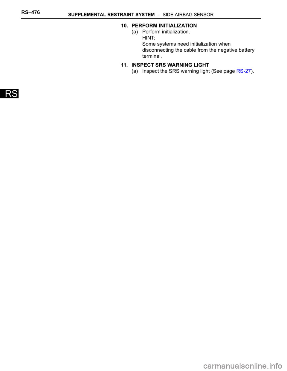
Page 234 of 3000
RS–476SUPPLEMENTAL RESTRAINT SYSTEM – SIDE AIRBAG SENSOR
RS
10. PERFORM INITIALIZATION
(a) Perform initialization.
HINT:
Some systems need initialization when
disconnecting the cable from the negative battery
terminal.
11. INSPECT SRS WARNING LIGHT
(a) Inspect the SRS warning light (See page RS-27).
Page 236 of 3000

THEFT DETERRENT – THEFT DETERRENT SYSTEMTD–3
TD
SYSTEM DESCRIPTION
1. OUTLINE OF THEFT DETERRENT SYSTEM
(a) When the theft deterrent system detects that the
vehicle is being tampered with, the system sets off
the alarm, causing the horns to sound and the lights
to light up or blink in order to alert people around the
vehicle to the theft.
(b) The theft deterrent system has 2 modes; one is the
active arming mode (see ACTIVE ARMING MODE)
and the other is passive arming mode (see
PASSIVE ARMING MODE). The passive arming
mode can be switched ON/OFF using the specified
method.
(c) Each mode has 4 states; a disarmed state, an
arming preparation state, an armed state and an
alarm sounding state.
(1) Disarmed state:
• The alarm function is not operating.
• The theft deterrent system is not operating.
(2) Arming preparation state:
• The time until the system goes into the armed
state.
• The theft deterrent system is not operating.
(3) Armed state:
• The theft deterrent system is operating.
(4) Alarm sounding state:
• Alarm function is operating.
Alarm time:
Approx. 60 sec.
Refer to table below for alarm method and time:
HINT:
If any of the doors are unlocked with no key in
the ignition key cylinder during the armed state,
a forced door lock signal will be output (see
FORCED DOOR LOCK CONTROL).
2. ACTIVE ARMING MODE
HINT:
• Active arming mode starts the alarm control
immediately after the doors are locked.
• This system activates as described in the diagram
below when one of items for each condition is met.
Alarm MethodHeadlight Blinking (approx. 0.4 second cycles)
Taillight Blinking (approx. 0.4 second cycles)
Hazard Warning Light Blinking (cycles of flasher relay)
Interior Light Illuminating
Vehicle HornSounding
(approx. 0.4 second cycles)
Security HornSounding
(approx. 0.4 second cycles)
Alarm Time Approx. 60 sec.
Page 244 of 3000
EI–4ENGINE IMMOBILISER – ENGINE IMMOBILISER SYSTEM
EI
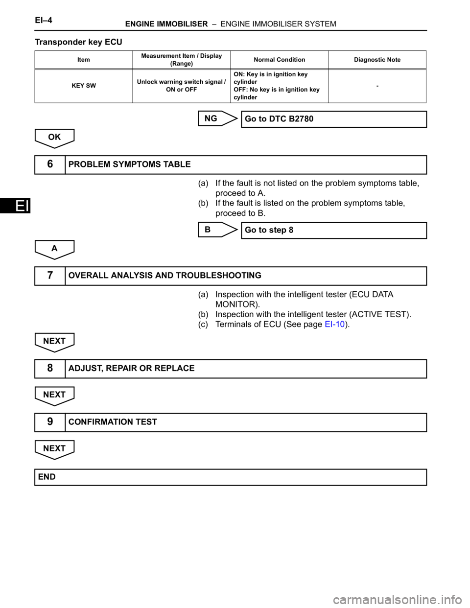
Transponder key ECU
NG
OK
(a) If the fault is not listed on the problem symptoms table,
proceed to A.
(b) If the fault is listed on the problem symptoms table,
proceed to B.
B
A
(a) Inspection with the intelligent tester (ECU DATA
MONITOR).
(b) Inspection with the intelligent tester (ACTIVE TEST).
(c) Terminals of ECU (See page EI-10).
NEXT
NEXT
NEXT
ItemMeasurement Item / Display
(Range)Normal Condition Diagnostic Note
KEY SWUnlock warning switch signal /
ON or OFFON: Key is in ignition key
cylinder
OFF: No key is in ignition key
cylinder-
Go to DTC B2780
6PROBLEM SYMPTOMS TABLE
Go to step 8
7OVERALL ANALYSIS AND TROUBLESHOOTING
8ADJUST, REPAIR OR REPLACE
9CONFIRMATION TEST
END
Page 283 of 3000
WS–66WINDSHIELD / WINDOWGLASS – WINDOW DEFOGGER SYSTEM
WS
PROBLEM SYMPTOMS TABLE
WINDOW DEFOGGER SYSTEM
ON-VEHICLE INSPECTION
1. INSPECT BACK WINDOW (DEFOGGER WIRE)
NOTICE:
• When cleaning the glass, wipe the glass along the
wire using a soft and dry cloth. Take care not to
damage the wires.
• Do not use detergents or glass cleaners including
abrasive ingredients.
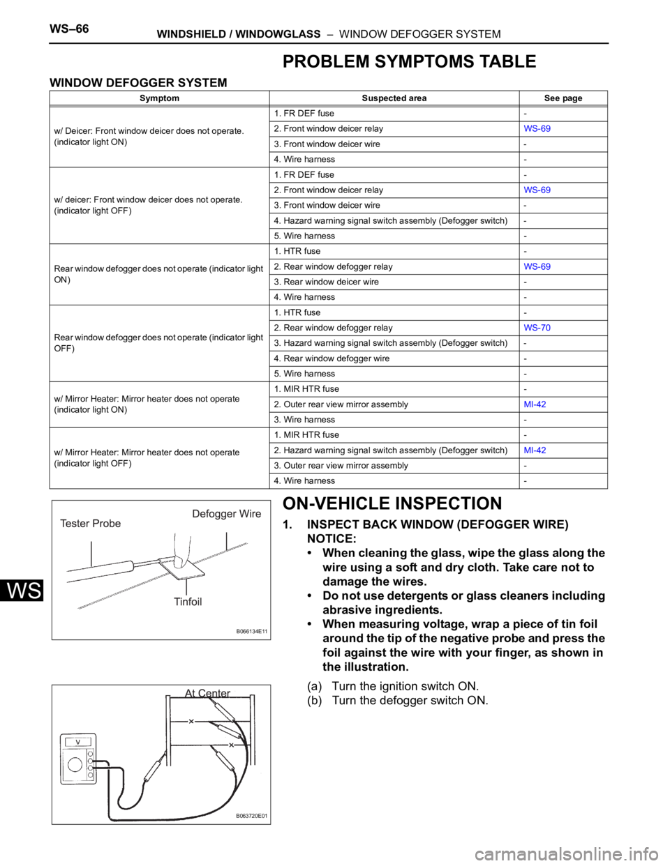
• When measuring voltage, wrap a piece of tin foil
around the tip of the negative probe and press the
foil against the wire with your finger, as shown in
the illustration.
(a) Turn the ignition switch ON.
(b) Turn the defogger switch ON.
Symptom Suspected area See page
w/ Deicer: Front window deicer does not operate.
(indicator light ON)1. FR DEF fuse -
2. Front window deicer relayWS-69
3. Front window deicer wire -
4. Wire harness -
w/ deicer: Front window deicer does not operate.
(indicator light OFF)1. FR DEF fuse -
2. Front window deicer relayWS-69
3. Front window deicer wire -
4. Hazard warning signal switch assembly (Defogger switch) -
5. Wire harness -
Rear window defogger does not operate (indicator light
ON)1. HTR fuse -
2. Rear window defogger relayWS-69
3. Rear window deicer wire -
4. Wire harness -
Rear window defogger does not operate (indicator light
OFF)1. HTR fuse -
2. Rear window defogger relayWS-70
3. Hazard warning signal switch assembly (Defogger switch) -
4. Rear window defogger wire -
5. Wire harness -
w/ Mirror Heater: Mirror heater does not operate
(indicator light ON)1. MIR HTR fuse -
2. Outer rear view mirror assemblyMI-42
3. Wire harness -
w/ Mirror Heater: Mirror heater does not operate
(indicator light OFF)1. MIR HTR fuse -
2. Hazard warning signal switch assembly (Defogger switch)MI-42
3. Outer rear view mirror assembly -
4. Wire harness -
B066134E11
B063720E01
Page 300 of 3000
SE–8SEAT – FRONT POWER SEAT CONTROL SYSTEM
SE
Main body ECUPower seat control switch and
ECU• Driver side door courtesy light
switch signal
• Key unlock warning switch
signal
• Ignition switch signalBEAN Transmitting ECU
(Transmitter)Receiving ECU Signals Communication method
Page 1342 of 3000
2GR-FE CHARGING – CHARGING SYSTEMCH–7
CH
(b) Check that the belt fits properly in the ribbed
grooves.
HINT:
Check with your hand to confirm that the belt has
not slipped out of the groove on the bottom of the
pulley.
If it has slipped out, replace the V-ribbed belt. Install
a new V-ribbed belt correctly.
7. INSPECT GENERATOR WIRING
(a) Visually check the generator wiring.
(1) Check that the wiring is in good condition.
8. CHECK FOR ABNORMAL NOISES
(a) Listen for abnormal noises from the generator.
(1) Check that no abnormal noises are heard from
the generator while the engine is running.
9. CHECK CHARGE WARNING LIGHT CIRCUIT
(a) Turn the ignition switch to the ON position. Check
that the charge warning light comes on.
(b) Start the engine and check that the light goes off.
If the light does not operate as specified,
troubleshoot the charge warning light circuit.
10. INSPECT CHARGING CIRCUIT WITHOUT LOAD
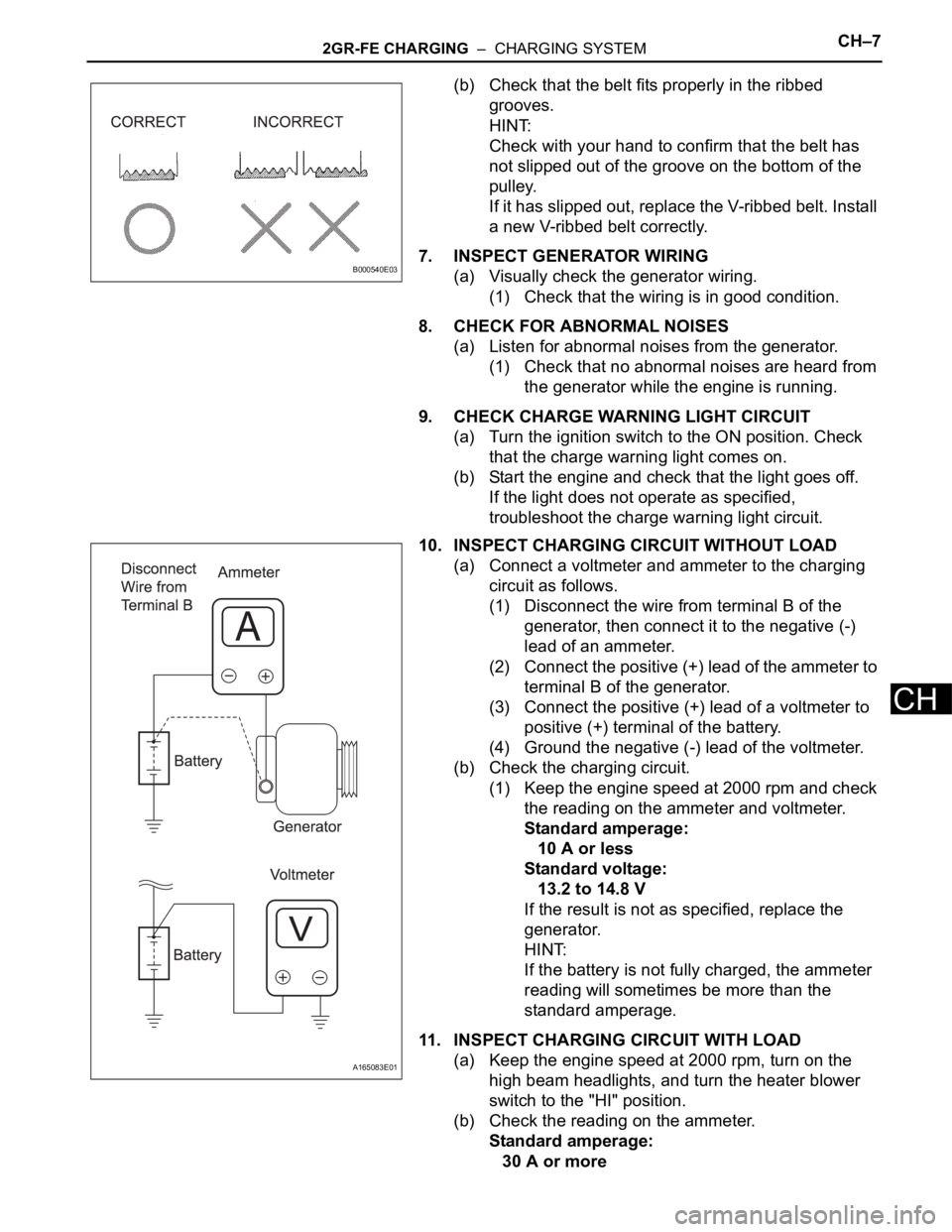
(a) Connect a voltmeter and ammeter to the charging
circuit as follows.
(1) Disconnect the wire from terminal B of the
generator, then connect it to the negative (-)
lead of an ammeter.
(2) Connect the positive (+) lead of the ammeter to
terminal B of the generator.
(3) Connect the positive (+) lead of a voltmeter to
positive (+) terminal of the battery.
(4) Ground the negative (-) lead of the voltmeter.
(b) Check the charging circuit.
(1) Keep the engine speed at 2000 rpm and check
the reading on the ammeter and voltmeter.
Standard amperage:
10 A or less
Standard voltage:
13.2 to 14.8 V
If the result is not as specified, replace the
generator.
HINT:
If the battery is not fully charged, the ammeter
reading will sometimes be more than the
standard amperage.
11. INSPECT CHARGING CIRCUIT WITH LOAD
(a) Keep the engine speed at 2000 rpm, turn on the
high beam headlights, and turn the heater blower
switch to the "HI" position.
(b) Check the reading on the ammeter.
Standard amperage:
30 A or more
B000540E03
A165083E01
Page 1344 of 3000
2GR-FE CHARGING – CHARGING SYSTEMCH–9
CH
INSPECTION PROCEDURE
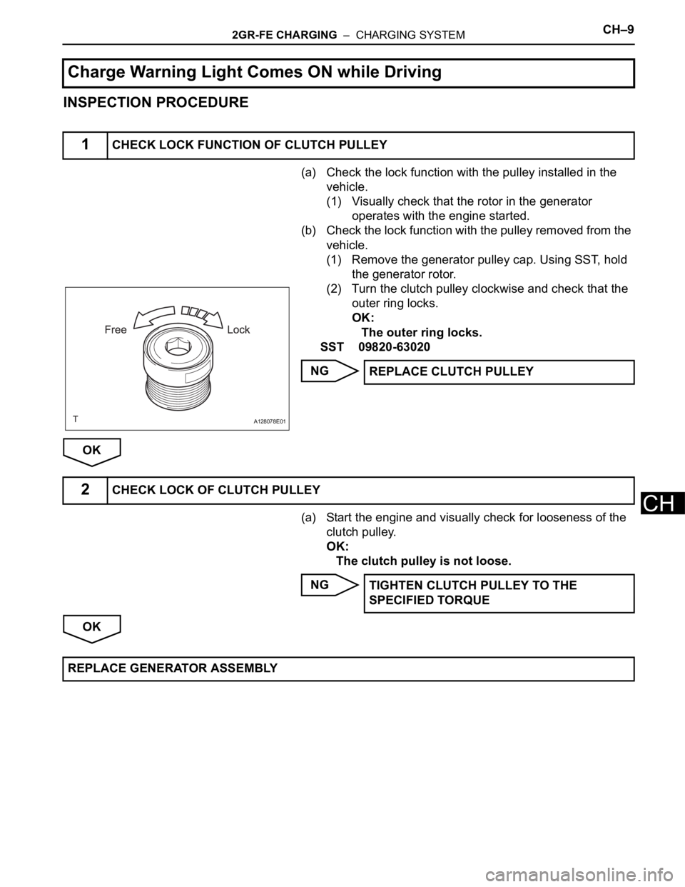
(a) Check the lock function with the pulley installed in the
vehicle.
(1) Visually check that the rotor in the generator
operates with the engine started.
(b) Check the lock function with the pulley removed from the
vehicle.
(1) Remove the generator pulley cap. Using SST, hold
the generator rotor.
(2) Turn the clutch pulley clockwise and check that the
outer ring locks.
OK:
The outer ring locks.
SST 09820-63020
NG
OK
(a) Start the engine and visually check for looseness of the
clutch pulley.
OK:
The clutch pulley is not loose.
NG
OK
Charge Warning Light Comes ON while Driving
1CHECK LOCK FUNCTION OF CLUTCH PULLEY
A128078E01
REPLACE CLUTCH PULLEY
2CHECK LOCK OF CLUTCH PULLEY
TIGHTEN CLUTCH PULLEY TO THE
SPECIFIED TORQUE
REPLACE GENERATOR ASSEMBLY