Page 1257 of 3000

2GR-FE COOLING – RADIATORCO–39
CO
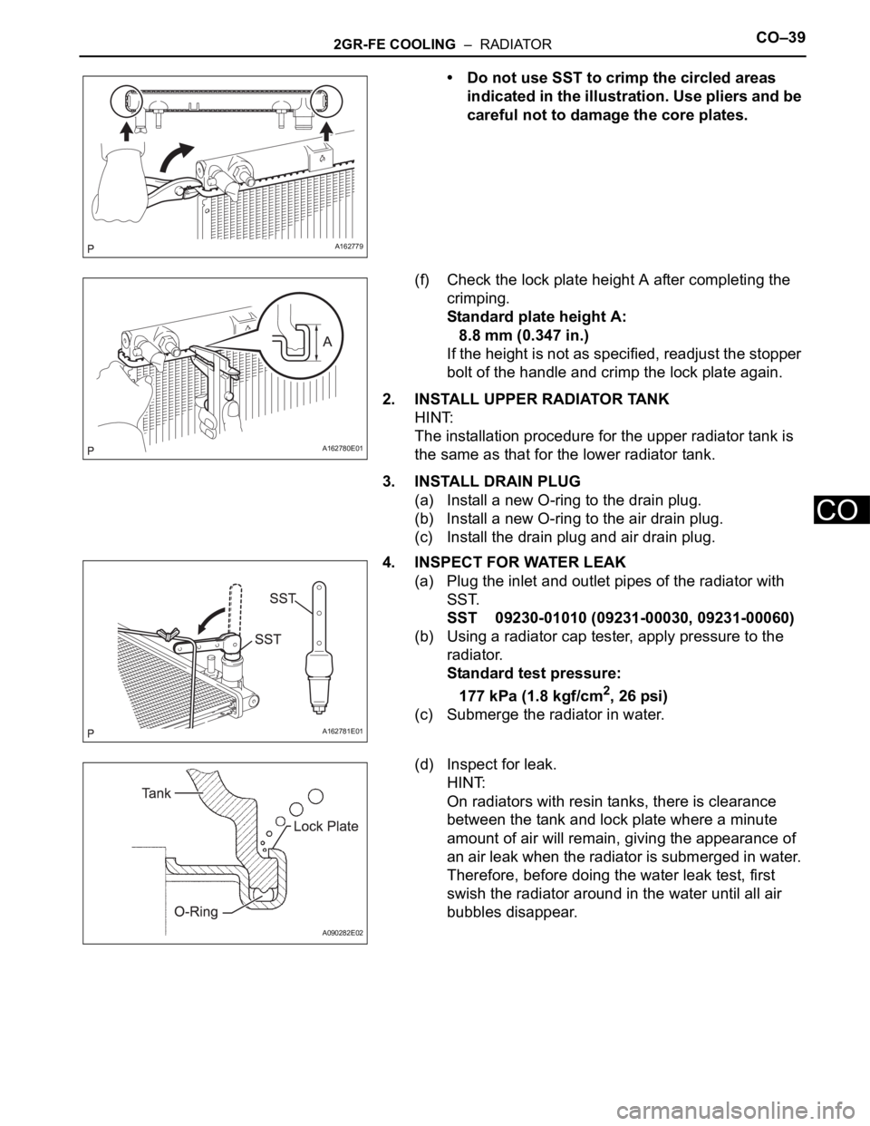
• Do not use SST to crimp the circled areas
indicated in the illustration. Use pliers and be
careful not to damage the core plates.
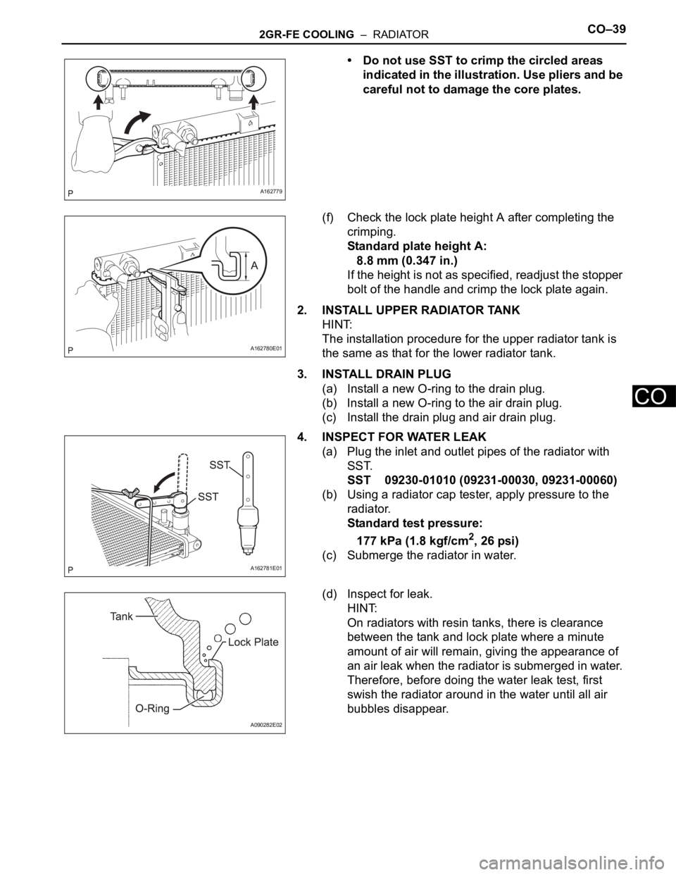
(f) Check the lock plate height A after completing the
crimping.
Standard plate height A:
8.8 mm (0.347 in.)
If the height is not as specified, readjust the stopper
bolt of the handle and crimp the lock plate again.
2. INSTALL UPPER RADIATOR TANK
HINT:
The installation procedure for the upper radiator tank is
the same as that for the lower radiator tank.
3. INSTALL DRAIN PLUG
(a) Install a new O-ring to the drain plug.
(b) Install a new O-ring to the air drain plug.
(c) Install the drain plug and air drain plug.
4. INSPECT FOR WATER LEAK
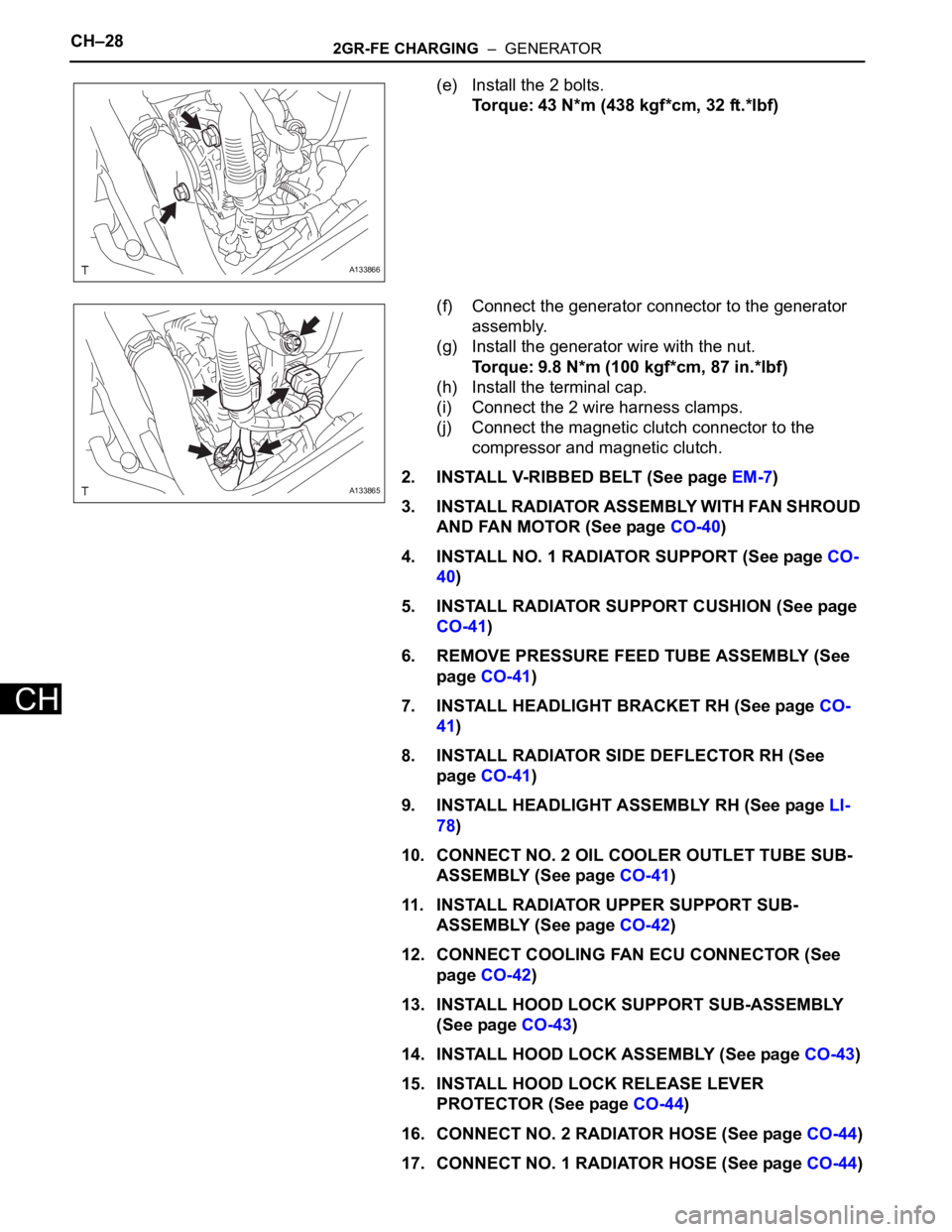
(a) Plug the inlet and outlet pipes of the radiator with
SST.
SST 09230-01010 (09231-00030, 09231-00060)
(b) Using a radiator cap tester, apply pressure to the
radiator.
Standard test pressure:
177 kPa (1.8 kgf/cm
2, 26 psi)
(c) Submerge the radiator in water.
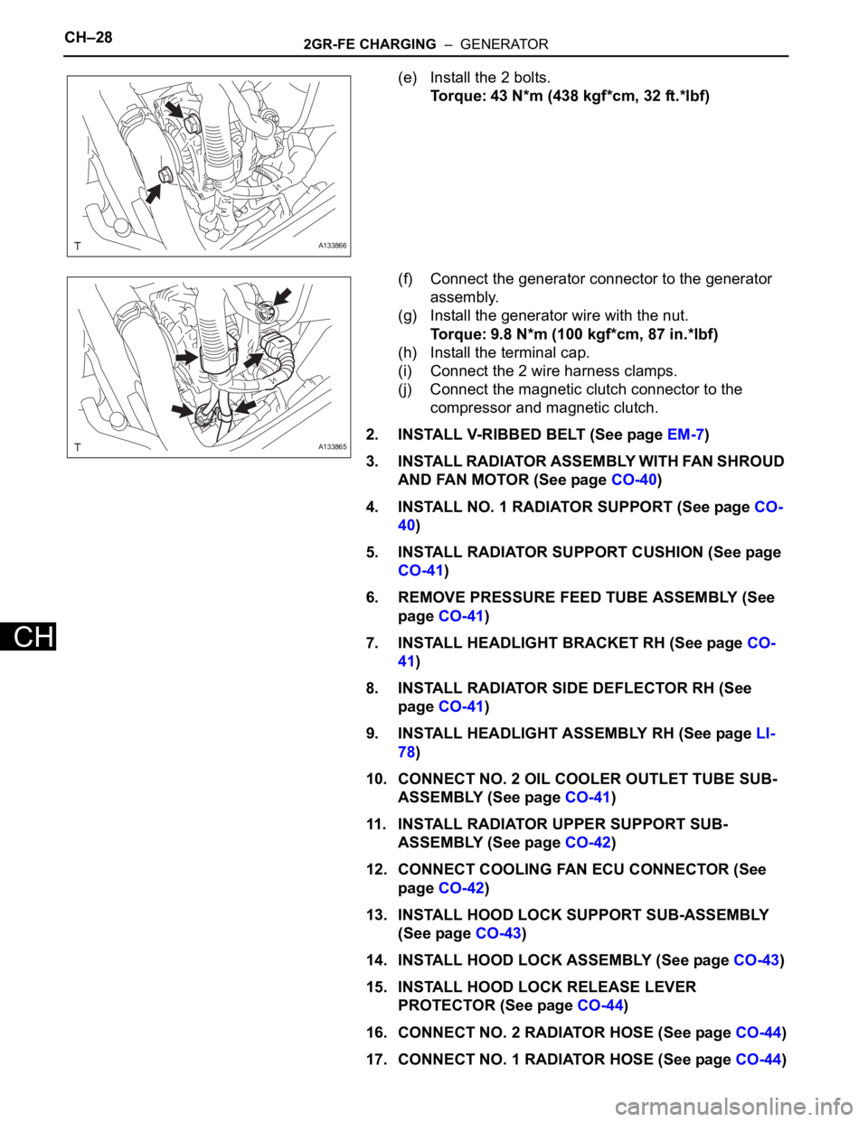
(d) Inspect for leak.
HINT:
On radiators with resin tanks, there is clearance
between the tank and lock plate where a minute
amount of air will remain, giving the appearance of
an air leak when the radiator is submerged in water.
Therefore, before doing the water leak test, first
swish the radiator around in the water until all air
bubbles disappear.
A162779
A162780E01
A162781E01
A090282E02
Page 1284 of 3000

2GR-FE COOLING – RADIATORCO–39
CO
• Do not use SST to crimp the circled areas
indicated in the illustration. Use pliers and be
careful not to damage the core plates.
(f) Check the lock plate height A after completing the
crimping.
Standard plate height A:
8.8 mm (0.347 in.)
If the height is not as specified, readjust the stopper
bolt of the handle and crimp the lock plate again.
2. INSTALL UPPER RADIATOR TANK
HINT:
The installation procedure for the upper radiator tank is
the same as that for the lower radiator tank.
3. INSTALL DRAIN PLUG
(a) Install a new O-ring to the drain plug.
(b) Install a new O-ring to the air drain plug.
(c) Install the drain plug and air drain plug.
4. INSPECT FOR WATER LEAK
(a) Plug the inlet and outlet pipes of the radiator with
SST.
SST 09230-01010 (09231-00030, 09231-00060)
(b) Using a radiator cap tester, apply pressure to the
radiator.
Standard test pressure:
177 kPa (1.8 kgf/cm
2, 26 psi)
(c) Submerge the radiator in water.
(d) Inspect for leak.
HINT:
On radiators with resin tanks, there is clearance
between the tank and lock plate where a minute
amount of air will remain, giving the appearance of
an air leak when the radiator is submerged in water.
Therefore, before doing the water leak test, first
swish the radiator around in the water until all air
bubbles disappear.
A162779
A162780E01
A162781E01
A090282E02
Page 1352 of 3000
2GR-FE CHARGING – GENERATORCH–17
CH
24. REMOVE RADIATOR SUPPORT CUSHION (See page
CO-32)
25. REMOVE NO. 1 RADIATOR SUPPORT (See page CO-
32)
26. REMOVE RADIATOR ASSEMBLY WITH FAN
SHROUD AND FAN MOTOR (See page CO-33)
27. REMOVE V-RIBBED BELT (See page EM-6)
28. REMOVE GENERATOR ASSEMBLY
(a) Remove the terminal cap.
(b) Remove the nut and disconnect the wire harness
from terminal B.
(c) Disconnect the generator connector from the
generator assembly.
(d) Disconnect the connector from the compressor and
magnetic clutch.
(e) Disconnect the 2 wire harness clamps.
(f) Remove the 2 bolts.
(g) Remove the bolt from the cylinder block.
(h) Disconnect the wire harness clamp and remove the
generator assembly.
(i) Remove the bolt and wire harness clamp stay.
A162681
A162682
A162683E01
A162684
Page 1357 of 3000
2GR-FE CHARGING – GENERATORCH–17
CH
24. REMOVE RADIATOR SUPPORT CUSHION (See page
CO-32)
25. REMOVE NO. 1 RADIATOR SUPPORT (See page CO-
32)
26. REMOVE RADIATOR ASSEMBLY WITH FAN
SHROUD AND FAN MOTOR (See page CO-33)
27. REMOVE V-RIBBED BELT (See page EM-6)
28. REMOVE GENERATOR ASSEMBLY
(a) Remove the terminal cap.
(b) Remove the nut and disconnect the wire harness
from terminal B.
(c) Disconnect the generator connector from the
generator assembly.
(d) Disconnect the connector from the compressor and
magnetic clutch.
(e) Disconnect the 2 wire harness clamps.
(f) Remove the 2 bolts.
(g) Remove the bolt from the cylinder block.
(h) Disconnect the wire harness clamp and remove the
generator assembly.
(i) Remove the bolt and wire harness clamp stay.
A162681
A162682
A162683E01
A162684
Page 1368 of 3000

CH–282GR-FE CHARGING – GENERATOR
CH
(e) Install the 2 bolts.
Torque: 43 N*m (438 kgf*cm, 32 ft.*lbf)
(f) Connect the generator connector to the generator
assembly.
(g) Install the generator wire with the nut.
Torque: 9.8 N*m (100 kgf*cm, 87 in.*lbf)
(h) Install the terminal cap.
(i) Connect the 2 wire harness clamps.
(j) Connect the magnetic clutch connector to the
compressor and magnetic clutch.
2. INSTALL V-RIBBED BELT (See page EM-7)
3. INSTALL RADIATOR ASSEMBLY WITH FAN SHROUD
AND FAN MOTOR (See page CO-40)
4. INSTALL NO. 1 RADIATOR SUPPORT (See page CO-
40)
5. INSTALL RADIATOR SUPPORT CUSHION (See page
CO-41)
6. REMOVE PRESSURE FEED TUBE ASSEMBLY (See
page CO-41)
7. INSTALL HEADLIGHT BRACKET RH (See page CO-
41)
8. INSTALL RADIATOR SIDE DEFLECTOR RH (See
page CO-41)
9. INSTALL HEADLIGHT ASSEMBLY RH (See page LI-
78)
10. CONNECT NO. 2 OIL COOLER OUTLET TUBE SUB-
ASSEMBLY (See page CO-41)
11. INSTALL RADIATOR UPPER SUPPORT SUB-
ASSEMBLY (See page CO-42)
12. CONNECT COOLING FAN ECU CONNECTOR (See
page CO-42)
13. INSTALL HOOD LOCK SUPPORT SUB-ASSEMBLY
(See page CO-43)
14. INSTALL HOOD LOCK ASSEMBLY (See page CO-43)
15. INSTALL HOOD LOCK RELEASE LEVER
PROTECTOR (See page CO-44)
16. CONNECT NO. 2 RADIATOR HOSE (See page CO-44)
17. CONNECT NO. 1 RADIATOR HOSE (See page CO-44)
A133866
A133865
Page 1377 of 3000

CH–282GR-FE CHARGING – GENERATOR
CH
(e) Install the 2 bolts.
Torque: 43 N*m (438 kgf*cm, 32 ft.*lbf)
(f) Connect the generator connector to the generator
assembly.
(g) Install the generator wire with the nut.
Torque: 9.8 N*m (100 kgf*cm, 87 in.*lbf)
(h) Install the terminal cap.
(i) Connect the 2 wire harness clamps.
(j) Connect the magnetic clutch connector to the
compressor and magnetic clutch.
2. INSTALL V-RIBBED BELT (See page EM-7)
3. INSTALL RADIATOR ASSEMBLY WITH FAN SHROUD
AND FAN MOTOR (See page CO-40)
4. INSTALL NO. 1 RADIATOR SUPPORT (See page CO-
40)
5. INSTALL RADIATOR SUPPORT CUSHION (See page
CO-41)
6. REMOVE PRESSURE FEED TUBE ASSEMBLY (See
page CO-41)
7. INSTALL HEADLIGHT BRACKET RH (See page CO-
41)
8. INSTALL RADIATOR SIDE DEFLECTOR RH (See
page CO-41)
9. INSTALL HEADLIGHT ASSEMBLY RH (See page LI-
78)
10. CONNECT NO. 2 OIL COOLER OUTLET TUBE SUB-
ASSEMBLY (See page CO-41)
11. INSTALL RADIATOR UPPER SUPPORT SUB-
ASSEMBLY (See page CO-42)
12. CONNECT COOLING FAN ECU CONNECTOR (See
page CO-42)
13. INSTALL HOOD LOCK SUPPORT SUB-ASSEMBLY
(See page CO-43)
14. INSTALL HOOD LOCK ASSEMBLY (See page CO-43)
15. INSTALL HOOD LOCK RELEASE LEVER
PROTECTOR (See page CO-44)
16. CONNECT NO. 2 RADIATOR HOSE (See page CO-44)
17. CONNECT NO. 1 RADIATOR HOSE (See page CO-44)
A133866
A133865