Page 192 of 3000
PS–10POWER STEERING – VANE PUMP
PS
8. REMOVE VANE PUMP ASSEMBLY
(a) Using SST, loosen bolt (A) and remove bolt (B), and
then remove the vane pump assembly.
SST 09249-63010
(b) Remove the bolt from the vane pump assembly.
DISASSEMBLY
1. HOLD VANE PUMP ASSEMBLY
(a) Using SST, hold the vane pump assembly in a vise.
SST 09630-00014 (09631-00132)
2. REMOVE POWER STEERING SUCTION PORT UNION
(a) Remove the bolt and the power steering suction port
union from the vane pump front housing.
(b) Using a screwdriver, remove the O-ring from the
power steering suction port union.
3. REMOVE POWER STEERING FLUID PRESSURE
SWITCH
NOTICE:
Perform this procedure only when the power
steering fluid pressure switch is replaced.
C158999E01
C135238
C141305E01
C133179
Page 193 of 3000
POWER STEERING – VANE PUMPPS–11
PS
(a) Remove the power steering fluid pressure switch
from the vane pump front housing.
4. REMOVE FLOW CONTROL VALVE ASSEMBLY
(a) Remove the pressure port union from the vane
pump front housing.
(b) Remove the O-ring from the pressure port union.
(c) Remove the flow control valve assembly and the
flow control valve compression spring from the vane
pump front housing.
5. REMOVE VANE PUMP REAR HOUSING
(a) Remove the 4 bolts and vane pump rear housing
from the vane pump front housing.
(b) Using a screwdriver, remove the O-ring from the
vane pump rear housing.
HINT:
Tape the screwdriver tip before use.
6. REMOVE VANE PUMP SHAFT WITH PULLEY
(a) Using 2 screwdrivers, remove the vane pump shaft
snap ring from the vane pump shaft with pulley.
(b) Remove the vane pump shaft with pulley.
C133180
C158998
C107024
C107025E02
C057767
Page 194 of 3000
PS–12POWER STEERING – VANE PUMP
PS
7. REMOVE VANE PUMP ROTOR
(a) Remove the 10 vane pump plates.
(b) Remove the vane pump rotor.
8. REMOVE VANE PUMP CAM RING
(a) Remove the vane pump cam ring from the vane
pump front housing.
9. REMOVE VANE PUMP FRONT SIDE PLATE
(a) Remove the vane pump front side plate from the
vane pump front housing.
(b) Using a screwdriver, remove the O-ring from the
vane pump front side plate.
HINT:
Tape the screwdriver tip before use.
(c) Remove the O-ring from the vane pump front
housing.
C114697
C114698
C114699
C107029E02
C114700
Page 195 of 3000

POWER STEERING – VANE PUMPPS–13
PS
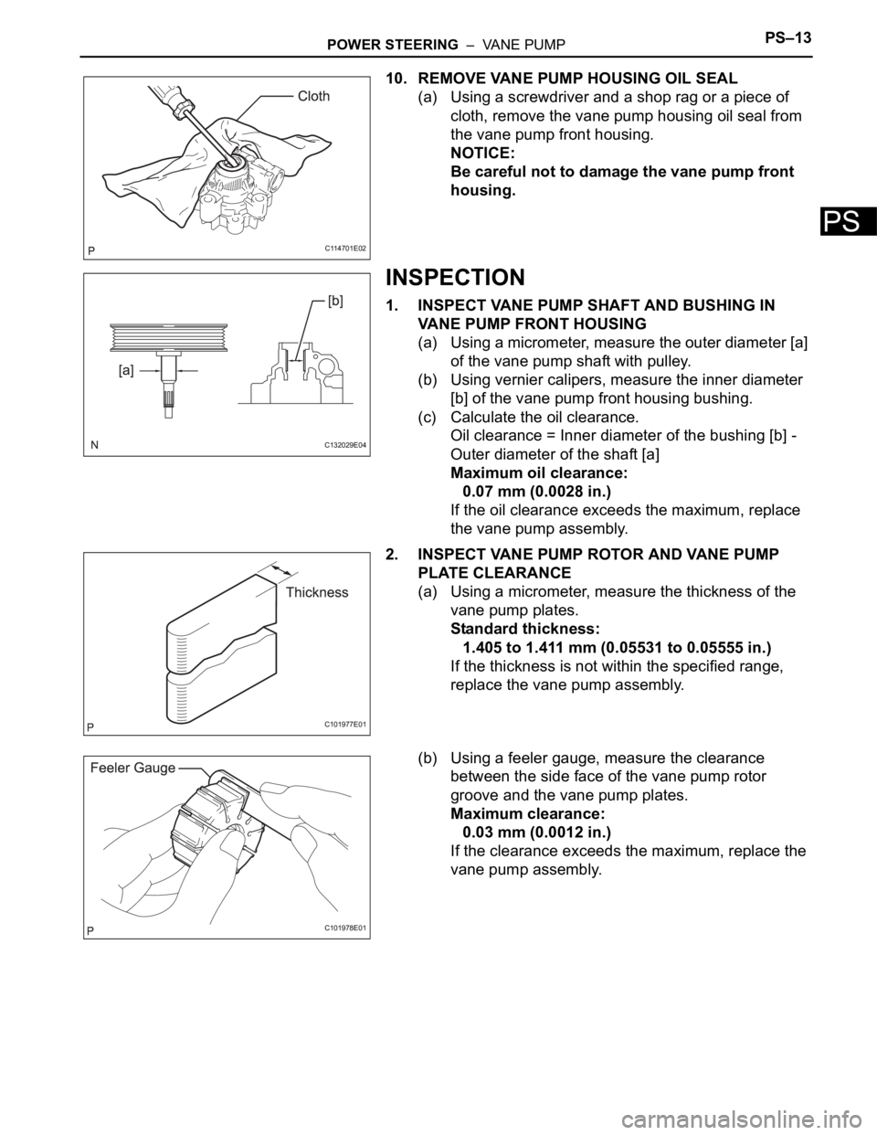
10. REMOVE VANE PUMP HOUSING OIL SEAL
(a) Using a screwdriver and a shop rag or a piece of
cloth, remove the vane pump housing oil seal from
the vane pump front housing.
NOTICE:
Be careful not to damage the vane pump front
housing.
INSPECTION
1. INSPECT VANE PUMP SHAFT AND BUSHING IN
VANE PUMP FRONT HOUSING
(a) Using a micrometer, measure the outer diameter [a]
of the vane pump shaft with pulley.
(b) Using vernier calipers, measure the inner diameter
[b] of the vane pump front housing bushing.
(c) Calculate the oil clearance.
Oil clearance = Inner diameter of the bushing [b] -
Outer diameter of the shaft [a]
Maximum oil clearance:
0.07 mm (0.0028 in.)
If the oil clearance exceeds the maximum, replace
the vane pump assembly.
2. INSPECT VANE PUMP ROTOR AND VANE PUMP
PLATE CLEARANCE
(a) Using a micrometer, measure the thickness of the
vane pump plates.
Standard thickness:
1.405 to 1.411 mm (0.05531 to 0.05555 in.)
If the thickness is not within the specified range,
replace the vane pump assembly.
(b) Using a feeler gauge, measure the clearance
between the side face of the vane pump rotor
groove and the vane pump plates.
Maximum clearance:
0.03 mm (0.0012 in.)
If the clearance exceeds the maximum, replace the
vane pump assembly.
C114701E02
C132029E04
C101977E01
C101978E01
Page 196 of 3000

PS–14POWER STEERING – VANE PUMP
PS
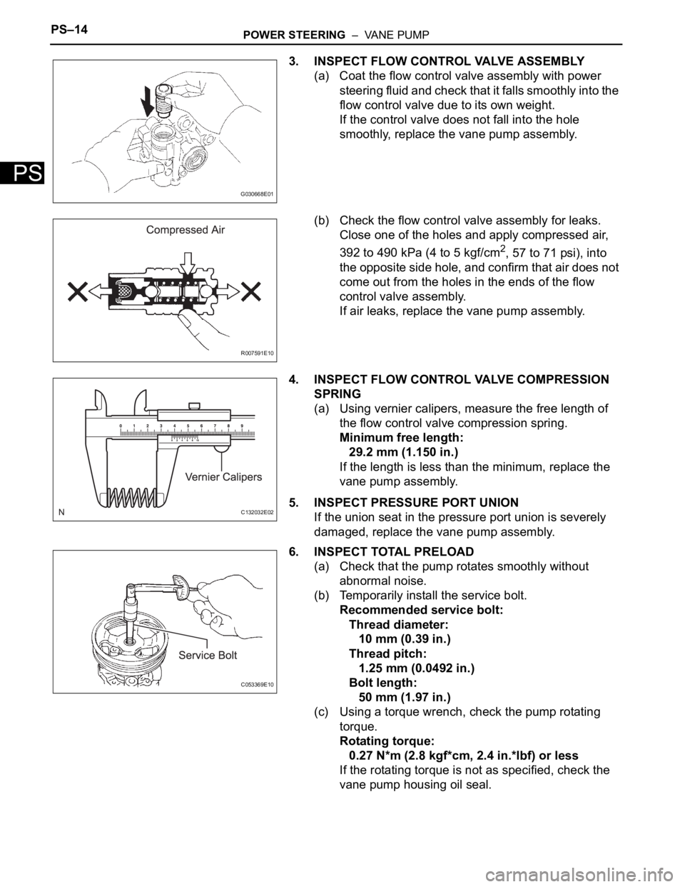
3. INSPECT FLOW CONTROL VALVE ASSEMBLY
(a) Coat the flow control valve assembly with power
steering fluid and check that it falls smoothly into the
flow control valve due to its own weight.
If the control valve does not fall into the hole
smoothly, replace the vane pump assembly.
(b) Check the flow control valve assembly for leaks.
Close one of the holes and apply compressed air,
392 to 490 kPa (4 to 5 kgf/cm
2, 57 to 71 psi), into
the opposite side hole, and confirm that air does not
come out from the holes in the ends of the flow
control valve assembly.
If air leaks, replace the vane pump assembly.
4. INSPECT FLOW CONTROL VALVE COMPRESSION
SPRING
(a) Using vernier calipers, measure the free length of
the flow control valve compression spring.
Minimum free length:
29.2 mm (1.150 in.)
If the length is less than the minimum, replace the
vane pump assembly.
5. INSPECT PRESSURE PORT UNION
If the union seat in the pressure port union is severely
damaged, replace the vane pump assembly.
6. INSPECT TOTAL PRELOAD
(a) Check that the pump rotates smoothly without
abnormal noise.
(b) Temporarily install the service bolt.
Recommended service bolt:
Thread diameter:
10 mm (0.39 in.)
Thread pitch:
1.25 mm (0.0492 in.)
Bolt length:
50 mm (1.97 in.)
(c) Using a torque wrench, check the pump rotating
torque.
Rotating torque:
0.27 N*m (2.8 kgf*cm, 2.4 in.*lbf) or less
If the rotating torque is not as specified, check the
vane pump housing oil seal.
G030668E01
R007591E10
C132032E02
C053369E10
Page 366 of 3000

ES–482GR-FE ENGINE CONTROL SYSTEM – SFI SYSTEM
ES
O2FT B2 S2 Fuel trim at heated oxygen sensor Same as SHORT FT #2
AF FT B1 S1 Fuel trim at A/F sensor -
AF FT B2 S1 Fuel trim at A/F sensor -
CAT TEMP B1 S1 Catalyst temperature -
CAT TEMP B2 S1 Catalyst temperature -
CAT TEMP B1 S2 Catalyst temperature -
CAT TEMP B2 S2 Catalyst temperature -
S O2S B1 S2 Heated oxygen sensor impedance (Sensor 2) -
S O2S B2 S2 Heated oxygen sensor impedance (Sensor 2) -
INI COOL TEMP Initial engine coolant temperature -
INI INTAKE TEMP Initial intake air temperature -
INJ VOL Injection volume -
STARTER SIG Starter signal -
PS SW Power steering signal -
PS SIGNAL Power steering signal (history)This signal status usually ON until ignition
switch turned off
CTP SW Closed throttle position switch -
A/C SIGNAL A/C signal -
ELECT LOAD SIG Electrical load signal -
STOP LIGHT SW Stop light switch -
BATTERY VOLTAGE Battery voltage -
ATM PRESSURE Atmospheric pressure -
FUEL PMP SP CTL Fuel pump speed control status -
ACIS VSVVSV for Air Intake Control Induction System
(AICS)-
VVT CTRL B2 VVT control (bank 2 Intake side) status -
EVAP (Purge) VSV EVAP purge VSV -
FUEL PUMP/SPD Fuel pump speed statusVSV for EVAP controlled by ECM (ground
side duty control)
VACUUM PUMP Key-off EVAP system pump status -
EVAP VENT VAL Key-off EVAP system vent valve status -
FAN MOTOR Electric fan motor -
TC/TE1 TC and TE1 terminals of DLC3 -
ACM ACM control status -
VVTL AIM ANGL #1 VVT aim angle -
VVT CHNG ANGL #1 VVT change angle -
VVT OCV DUTY B1 VVT OCV operation duty -
VVT EX HOLD B1VVT exhaust hold duty ratio learning value
(bank 1 Exhaust side)-
VVT EX CHG ANG1 VVT change angle (bank 1 Exhaust side) -
VVT EX OCV D B1VVT OCV (bank 1 Exhaust side) operation
duty-
VVTL AIM ANGL#2 VVT aim angle (bank 2 Intake side) -
VVT CHNG ANGL#2 VVT change angle (bank 2 Intake side) -
VVT OCV DUTY B2 VVT OCV (bank 2 Intake side) operation duty -
VVT EX HOLD B2VVT exhaust hold duty ratio learning value
(bank 2 Exhaust side)-
VVT EX CHG ANG2 VVT change angle (bank 2 Exhaust side) -
VVT EX OCV D B2VVT OCV (bank 2 Exhaust side) operation
duty- LABEL
(Intelligent Tester Display)Measurement Item Diagnostic Note
Page 832 of 3000

ES–482GR-FE ENGINE CONTROL SYSTEM – SFI SYSTEM
ES
O2FT B2 S2 Fuel trim at heated oxygen sensor Same as SHORT FT #2
AF FT B1 S1 Fuel trim at A/F sensor -
AF FT B2 S1 Fuel trim at A/F sensor -
CAT TEMP B1 S1 Catalyst temperature -
CAT TEMP B2 S1 Catalyst temperature -
CAT TEMP B1 S2 Catalyst temperature -
CAT TEMP B2 S2 Catalyst temperature -
S O2S B1 S2 Heated oxygen sensor impedance (Sensor 2) -
S O2S B2 S2 Heated oxygen sensor impedance (Sensor 2) -
INI COOL TEMP Initial engine coolant temperature -
INI INTAKE TEMP Initial intake air temperature -
INJ VOL Injection volume -
STARTER SIG Starter signal -
PS SW Power steering signal -
PS SIGNAL Power steering signal (history)This signal status usually ON until ignition
switch turned off
CTP SW Closed throttle position switch -
A/C SIGNAL A/C signal -
ELECT LOAD SIG Electrical load signal -
STOP LIGHT SW Stop light switch -
BATTERY VOLTAGE Battery voltage -
ATM PRESSURE Atmospheric pressure -
FUEL PMP SP CTL Fuel pump speed control status -
ACIS VSVVSV for Air Intake Control Induction System
(AICS)-
VVT CTRL B2 VVT control (bank 2 Intake side) status -
EVAP (Purge) VSV EVAP purge VSV -
FUEL PUMP/SPD Fuel pump speed statusVSV for EVAP controlled by ECM (ground
side duty control)
VACUUM PUMP Key-off EVAP system pump status -
EVAP VENT VAL Key-off EVAP system vent valve status -
FAN MOTOR Electric fan motor -
TC/TE1 TC and TE1 terminals of DLC3 -
ACM ACM control status -
VVTL AIM ANGL #1 VVT aim angle -
VVT CHNG ANGL #1 VVT change angle -
VVT OCV DUTY B1 VVT OCV operation duty -
VVT EX HOLD B1VVT exhaust hold duty ratio learning value
(bank 1 Exhaust side)-
VVT EX CHG ANG1 VVT change angle (bank 1 Exhaust side) -
VVT EX OCV D B1VVT OCV (bank 1 Exhaust side) operation
duty-
VVTL AIM ANGL#2 VVT aim angle (bank 2 Intake side) -
VVT CHNG ANGL#2 VVT change angle (bank 2 Intake side) -
VVT OCV DUTY B2 VVT OCV (bank 2 Intake side) operation duty -
VVT EX HOLD B2VVT exhaust hold duty ratio learning value
(bank 2 Exhaust side)-
VVT EX CHG ANG2 VVT change angle (bank 2 Exhaust side) -
VVT EX OCV D B2VVT OCV (bank 2 Exhaust side) operation
duty- LABEL
(Intelligent Tester Display)Measurement Item Diagnostic Note
Page 869 of 3000
EM–522GR-FE ENGINE MECHANICAL – ENGINE ASSEMBLY
EM
(c) Install the engine mounting insulator RR with the 2
bolts.
Torque: 78 N*m (795 kgf*cm, 58 ft.*lbf)
(d) Connect the connector and clamp.
40. INSTALL POWER STEERING LINK (See page PS-39)
41. INSTALL FRONT STABILIZER BAR
HINT:
(See page SP-36).
42. REMOVE ENGINE HANGERS
(a) Remove the 4 bolts and 2 engine hangers.
43. INSTALL VANE PUMP ASSEMBLY
(a) Install the vane pump with the 2 bolts and nut.
Torque: 43 N*m (438 kgf*cm, 32 ft.*lbf)
(b) Install the 2 pressure feed tube clamp nuts.
Torque: 7.8 N*m (80 kgf*cm, 69 in.*lbf)
(c) Connect the power steering oil pressure switch
connector.
44. INSTALL ENGINE ASSEMBLY WITH TRANSAXLE
(a) Set the engine assembly with transaxle on the
engine lifter.
(b) Install the engine assembly to the vehicle.
A155018
A155022
A129635E01
A139216
A155024