Page 879 of 3000

EM–622GR-FE ENGINE MECHANICAL – ENGINE ASSEMBLY
EM
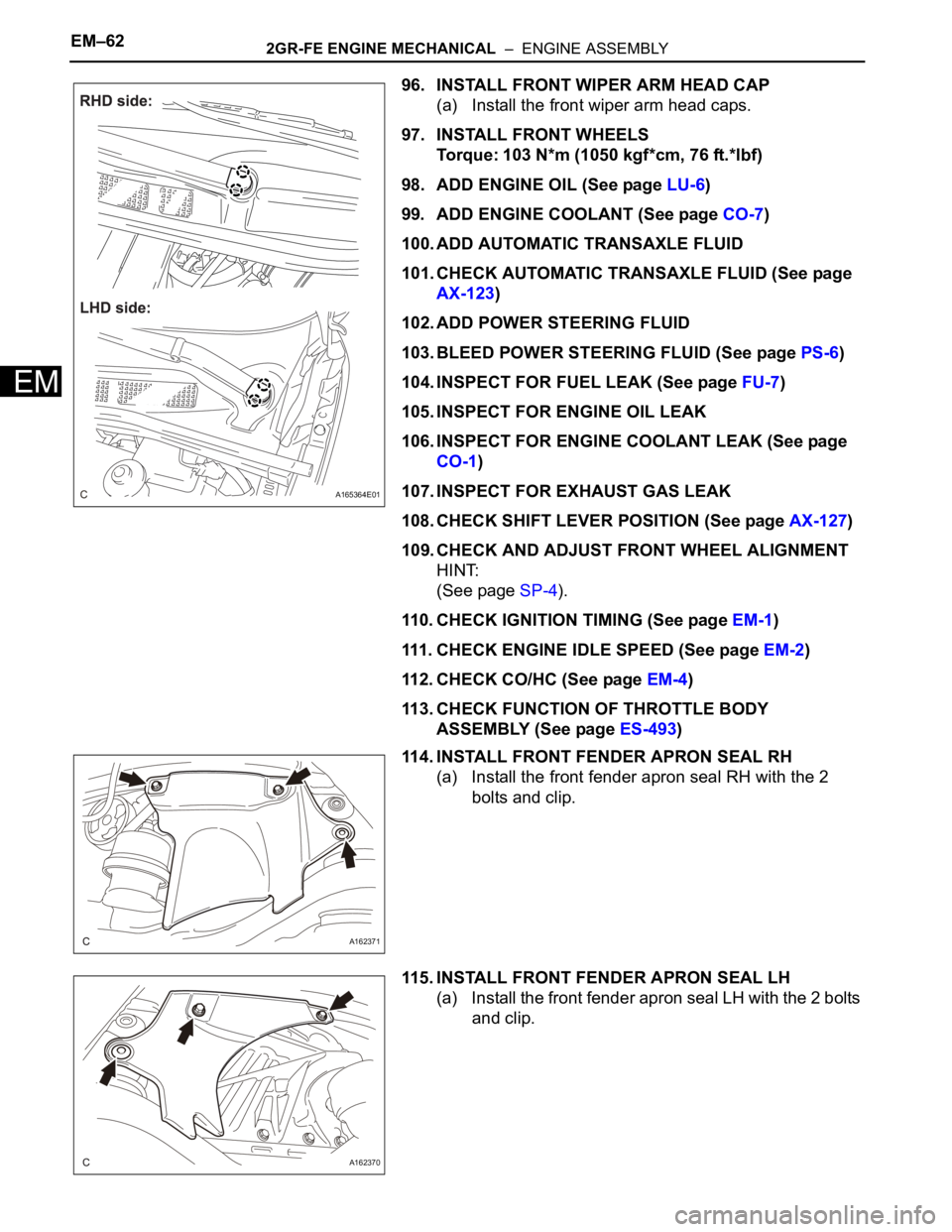
96. INSTALL FRONT WIPER ARM HEAD CAP
(a) Install the front wiper arm head caps.
97. INSTALL FRONT WHEELS
Torque: 103 N*m (1050 kgf*cm, 76 ft.*lbf)
98. ADD ENGINE OIL (See page LU-6)
99. ADD ENGINE COOLANT (See page CO-7)
100. ADD AUTOMATIC TRANSAXLE FLUID
101. CHECK AUTOMATIC TRANSAXLE FLUID (See page
AX-123)
102. ADD POWER STEERING FLUID
103. BLEED POWER STEERING FLUID (See page PS-6)
104. INSPECT FOR FUEL LEAK (See page FU-7)
105. INSPECT FOR ENGINE OIL LEAK
106. INSPECT FOR ENGINE COOLANT LEAK (See page
CO-1)
107. INSPECT FOR EXHAUST GAS LEAK
108. CHECK SHIFT LEVER POSITION (See page AX-127)
109. CHECK AND ADJUST FRONT WHEEL ALIGNMENT
HINT:
(See page SP-4).
110. CHECK IGNITION TIMING (See page EM-1)
111. CHECK ENGINE IDLE SPEED (See page EM-2)
112. CHECK CO/HC (See page EM-4)
113. CHECK FUNCTION OF THROTTLE BODY
ASSEMBLY (See page ES-493)
114. INSTALL FRONT FENDER APRON SEAL RH
(a) Install the front fender apron seal RH with the 2
bolts and clip.
115. INSTALL FRONT FENDER APRON SEAL LH
(a) Install the front fender apron seal LH with the 2 bolts
and clip.
A165364E01
A162371
A162370
Page 991 of 3000
EM–322GR-FE ENGINE MECHANICAL – ENGINE ASSEMBLY
EM
(c) Remove the clip and disconnect the transmission
control cable assembly from the control cable
bracket.
(d) Disconnect the control cable from the control cable
clamp.
38. DISCONNECT RETURN TUBE SUB-ASSEMBLY
(a) Using pliers, grip the claws of the 2 clips and slide
the 2 clips to disconnect the 2 return tube sub-
assemblies.
(b) Drain the power steering fluid.
NOTICE:
Take care not to damage the hose protector.
39. DISCONNECT NO. 1 OIL RESERVOIR TO PUMP
HOSE
(a) Using pliers, grip the claws of the clip and slide the
clip to disconnect the No. 1 oil reservoir to pump
hose from the oil reservoir tank.
40. DISCONNECT ENGINE WIRE
(a) Disconnect the engine wire from the engine room
junction block.
(1) Remove the nut and separate the wire harness.
(2) Using a screwdriver, unlock the engine room
junction block. Pull the engine room junction
block upward.
C089134E01
C090579
A163268
A155029
A155037
Page 994 of 3000
2GR-FE ENGINE MECHANICAL – ENGINE ASSEMBLYEM–35
EM
(b) Remove the 6 bolts, 2 nuts, and frame side rail
plates RH and LH.
(c) Remove the 6 bolts, 2 nuts, and front suspension
member brace rear RH and LH.
(d) Operate the engine lifter, then remove the engine
assembly from the vehicle.
NOTICE:
Make sure that the engine is clear of all wiring
and hoses.
62. REMOVE V-RIBBED BELT (See page EM-6)
63. REMOVE VANE PUMP ASSEMBLY
(a) Disconnect the power steering oil pressure switch
connector.
(b) Remove the 2 nuts.
(c) Loosen the bolt A.
(d) Remove the bolt B.
(e) Remove the bolt A and vane pump assembly.
64. REMOVE FRONT STABILIZER BAR (for 4WD)
HINT:
See page SP-35.
65. REMOVE POWER STEERING LINK
(a) Remove the 2 bolts and power steering link with
vane pump.
A162364
A162363
A155024
A139216E01
Page 1011 of 3000
EM–522GR-FE ENGINE MECHANICAL – ENGINE ASSEMBLY
EM
(c) Install the engine mounting insulator RR with the 2
bolts.
Torque: 78 N*m (795 kgf*cm, 58 ft.*lbf)
(d) Connect the connector and clamp.
40. INSTALL POWER STEERING LINK (See page PS-39)
41. INSTALL FRONT STABILIZER BAR
HINT:
(See page SP-36).
42. REMOVE ENGINE HANGERS
(a) Remove the 4 bolts and 2 engine hangers.
43. INSTALL VANE PUMP ASSEMBLY
(a) Install the vane pump with the 2 bolts and nut.
Torque: 43 N*m (438 kgf*cm, 32 ft.*lbf)
(b) Install the 2 pressure feed tube clamp nuts.
Torque: 7.8 N*m (80 kgf*cm, 69 in.*lbf)
(c) Connect the power steering oil pressure switch
connector.
44. INSTALL ENGINE ASSEMBLY WITH TRANSAXLE
(a) Set the engine assembly with transaxle on the
engine lifter.
(b) Install the engine assembly to the vehicle.
A155018
A155022
A129635E01
A139216
A155024
Page 1021 of 3000

EM–622GR-FE ENGINE MECHANICAL – ENGINE ASSEMBLY
EM
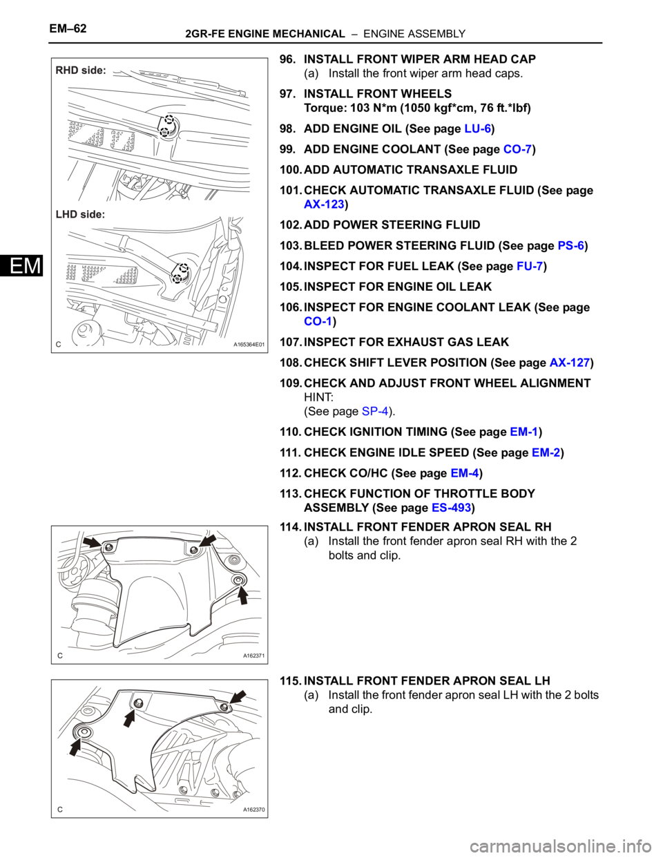
96. INSTALL FRONT WIPER ARM HEAD CAP
(a) Install the front wiper arm head caps.
97. INSTALL FRONT WHEELS
Torque: 103 N*m (1050 kgf*cm, 76 ft.*lbf)
98. ADD ENGINE OIL (See page LU-6)
99. ADD ENGINE COOLANT (See page CO-7)
100. ADD AUTOMATIC TRANSAXLE FLUID
101. CHECK AUTOMATIC TRANSAXLE FLUID (See page
AX-123)
102. ADD POWER STEERING FLUID
103. BLEED POWER STEERING FLUID (See page PS-6)
104. INSPECT FOR FUEL LEAK (See page FU-7)
105. INSPECT FOR ENGINE OIL LEAK
106. INSPECT FOR ENGINE COOLANT LEAK (See page
CO-1)
107. INSPECT FOR EXHAUST GAS LEAK
108. CHECK SHIFT LEVER POSITION (See page AX-127)
109. CHECK AND ADJUST FRONT WHEEL ALIGNMENT
HINT:
(See page SP-4).
110. CHECK IGNITION TIMING (See page EM-1)
111. CHECK ENGINE IDLE SPEED (See page EM-2)
112. CHECK CO/HC (See page EM-4)
113. CHECK FUNCTION OF THROTTLE BODY
ASSEMBLY (See page ES-493)
114. INSTALL FRONT FENDER APRON SEAL RH
(a) Install the front fender apron seal RH with the 2
bolts and clip.
115. INSTALL FRONT FENDER APRON SEAL LH
(a) Install the front fender apron seal LH with the 2 bolts
and clip.
A165364E01
A162371
A162370
Page 2204 of 3000

SP–28SUSPENSION – FRONT STABILIZER BAR (for 2WD)
SP
REMOVAL
1. REMOVE FRONT WHEELS
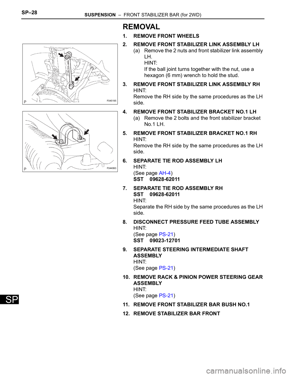
2. REMOVE FRONT STABILIZER LINK ASSEMBLY LH
(a) Remove the 2 nuts and front stabilizer link assembly
LH.
HINT:
If the ball joint turns together with the nut, use a
hexagon (6 mm) wrench to hold the stud.
3. REMOVE FRONT STABILIZER LINK ASSEMBLY RH
HINT:
Remove the RH side by the same procedures as the LH
side.
4. REMOVE FRONT STABILIZER BRACKET NO.1 LH
(a) Remove the 2 bolts and the front stabilizer bracket
No.1 LH.
5. REMOVE FRONT STABILIZER BRACKET NO.1 RH
HINT:
Remove the RH side by the same procedures as the LH
side.
6. SEPARATE TIE ROD ASSEMBLY LH
HINT:
(See page AH-4)
SST 09628-62011
7. SEPARATE TIE ROD ASSEMBLY RH
SST 09628-62011
HINT:
Separate the RH side by the same procedures as the LH
side.
8. DISCONNECT PRESSURE FEED TUBE ASSEMBLY
HINT:
(See page PS-21)
SST 09023-12701
9. SEPARATE STEERING INTERMEDIATE SHAFT
ASSEMBLY
HINT:
(See page PS-21)
10. REMOVE RACK & PINION POWER STEERING GEAR
ASSEMBLY
HINT:
(See page PS-21)
11. REMOVE FRONT STABILIZER BAR BUSH NO.1
12. REMOVE STABILIZER BAR FRONT
F045195
F044993
Page 2208 of 3000

SP–30SUSPENSION – FRONT STABILIZER BAR (for 2WD)
SP
INSTALLATION
1. INSTALL STABILIZER BAR FRONT
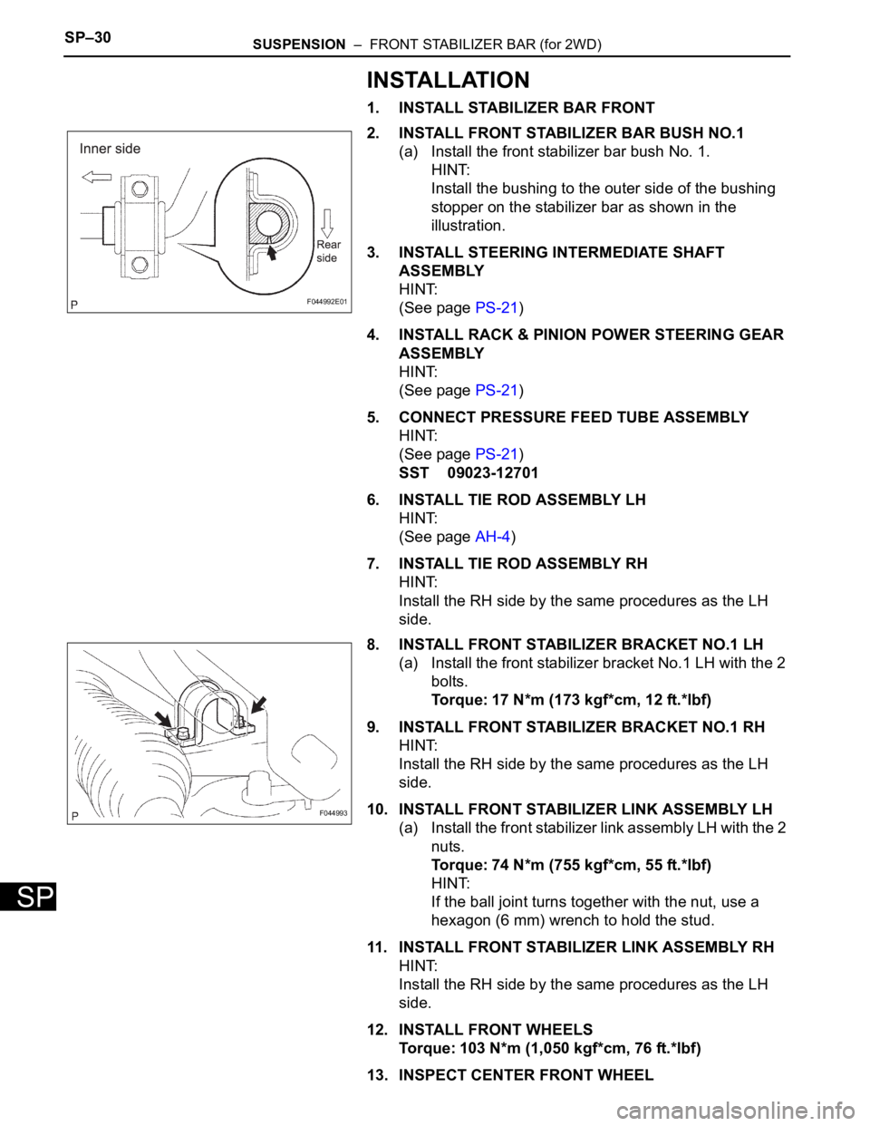
2. INSTALL FRONT STABILIZER BAR BUSH NO.1
(a) Install the front stabilizer bar bush No. 1.
HINT:
Install the bushing to the outer side of the bushing
stopper on the stabilizer bar as shown in the
illustration.
3. INSTALL STEERING INTERMEDIATE SHAFT
ASSEMBLY
HINT:
(See page PS-21)
4. INSTALL RACK & PINION POWER STEERING GEAR
ASSEMBLY
HINT:
(See page PS-21)
5. CONNECT PRESSURE FEED TUBE ASSEMBLY
HINT:
(See page PS-21)
SST 09023-12701
6. INSTALL TIE ROD ASSEMBLY LH
HINT:
(See page AH-4)
7. INSTALL TIE ROD ASSEMBLY RH
HINT:
Install the RH side by the same procedures as the LH
side.
8. INSTALL FRONT STABILIZER BRACKET NO.1 LH
(a) Install the front stabilizer bracket No.1 LH with the 2
bolts.
Torque: 17 N*m (173 kgf*cm, 12 ft.*lbf)
9. INSTALL FRONT STABILIZER BRACKET NO.1 RH
HINT:
Install the RH side by the same procedures as the LH
side.
10. INSTALL FRONT STABILIZER LINK ASSEMBLY LH
(a) Install the front stabilizer link assembly LH with the 2
nuts.
Torque: 74 N*m (755 kgf*cm, 55 ft.*lbf)
HINT:
If the ball joint turns together with the nut, use a
hexagon (6 mm) wrench to hold the stud.
11. INSTALL FRONT STABILIZER LINK ASSEMBLY RH
HINT:
Install the RH side by the same procedures as the LH
side.
12. INSTALL FRONT WHEELS
Torque: 103 N*m (1,050 kgf*cm, 76 ft.*lbf)
13. INSPECT CENTER FRONT WHEEL
F044992E01
F044993
Page 2209 of 3000
SUSPENSION – FRONT STABILIZER BAR (for 2WD)SP–31
SP
14. INSPECT STEERING WHEEL CENTER POINT
15. ADD POWER STEERING FLUID
16. BLEED POWER STEERING FLUID
HINT:
(See page SP-26)
17. CHECK POWER STEERING FLUID LEAKAGE
18. INSPECT AND ADJUST FRONT WHEEL ALIGNMENT
HINT:
(See page SP-4)