Page 204 of 3000

AIR CONDITIONING – COMPRESSOR AND MAGNETIC CLUTCHAC–227
AC
REMOVAL
1. RECOVER REFRIGERANT FROM REFRIGERATION
SYSTEM (See page AC-172)
2. REMOVE FRONT WHEEL RH
3. REMOVE FRONT FENDER APRON SEAL RH (See
page EM-26)
4. REMOVE V-RIBBED BELT (See page EM-6)
5. REMOVE RADIATOR AND FAN ASSEMBLY
(See page CO-28)
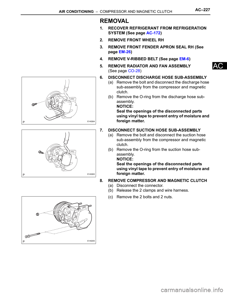
6. DISCONNECT DISCHARGE HOSE SUB-ASSEMBLY
(a) Remove the bolt and disconnect the discharge hose
sub-assembly from the compressor and magnetic
clutch.
(b) Remove the O-ring from the discharge hose sub-
assembly.
NOTICE:
Seal the openings of the disconnected parts
using vinyl tape to prevent entry of moisture and
foreign matter.
7. DISCONNECT SUCTION HOSE SUB-ASSEMBLY
(a) Remove the bolt and disconnect the suction hose
sub-assembly from the compressor and magnetic
clutch.
(b) Remove the O-ring from the suction hose sub-
assembly.
NOTICE:
Seal the openings of the disconnected parts
using vinyl tape to prevent entry of moisture and
foreign matter.
8. REMOVE COMPRESSOR AND MAGNETIC CLUTCH
(a) Disconnect the connector.
(b) Release the 2 clamps and wire harness.
(c) Remove the 2 bolts and 2 nuts.
E145264
E145265
E145255
Page 232 of 3000
RS–474SUPPLEMENTAL RESTRAINT SYSTEM – SIDE AIRBAG SENSOR
RS
REMOVAL
HINT:
• Use the same procedures for the RH side and LH side.
• The procedures listed below are for the LH side.
1. PRECAUTION
CAUTION:
Be sure to read "PRECAUTION" thoroughly before
servicing (See page RS-1).
2. DISCONNECT CABLE FROM NEGATIVE BATTERY
TERMINAL
CAUTION:
Wait for 90 seconds after disconnecting the cable to
prevent the airbag working.
3. REMOVE FRONT DOOR SCUFF PLATE LH
HINT:
(See page IR-7)
4. REMOVE REAR DOOR SCUFF PLATE LH
HINT:
(See page IR-7)
5. REMOVE FRONT DOOR OPENING TRIM
WEATHERSTRIP LH
HINT:
(See page IR-7)
6. REMOVE REAR DOOR WEATHERSTRIP LH (See
page IR-7)
7. REMOVE LAP BELT OUTER ANCHOR COVER LH
8. REMOVE CENTER PILLAR GARNISH LOWER LH
(See page IR-8)
9. REMOVE FRONT SEAT OUTER BELT ASSEMBLY
(See page SB-7)
10. REMOVE SIDE AIRBAG SENSOR LH
(a) Disconnect the connector from the side airbag
sensor LH.
(b) Remove the 2 nuts and the side airbag sensor LH.
H042693
Page 233 of 3000

SUPPLEMENTAL RESTRAINT SYSTEM – SIDE AIRBAG SENSORRS–475
RS
INSTALLATION
HINT:
• Use the same procedures for the RH side and LH side.
• The procedures listed below are for the LH side.
1. INSTALL SIDE AIRBAG SENSOR LH
(a) Check that the ignition switch is off.
(b) Check that the battery negative (-) terminal is
disconnected.
CAUTION:
After disconnecting the negative battery
terminal, wait for at least 90 seconds before
starting the operation.
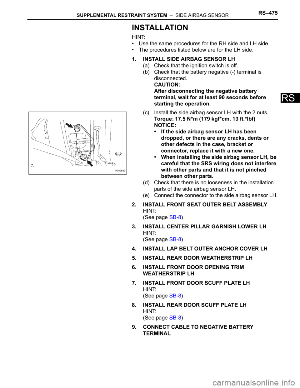
(c) Install the side airbag sensor LH with the 2 nuts.
Torque: 17.5 N*m (179 kgf*cm, 13 ft.*lbf)
NOTICE:
• If the side airbag sensor LH has been
dropped, or there are any cracks, dents or
other defects in the case, bracket or
connector, replace it with a new one.
• When installing the side airbag sensor LH, be
careful that the SRS wiring does not interfere
with other parts and that it is not pinched
between other parts.
(d) Check that there is no looseness in the installation
parts of the side airbag sensor LH.
(e) Connect the connector to the side airbag sensor LH.
2. INSTALL FRONT SEAT OUTER BELT ASSEMBLY
HINT:
(See page SB-8)
3. INSTALL CENTER PILLAR GARNISH LOWER LH
HINT:
(See page SB-8)
4. INSTALL LAP BELT OUTER ANCHOR COVER LH
5. INSTALL REAR DOOR WEATHERSTRIP LH
6. INSTALL FRONT DOOR OPENING TRIM
WEATHERSTRIP LH
7. INSTALL FRONT DOOR SCUFF PLATE LH
HINT:
(See page SB-8)
8. INSTALL REAR DOOR SCUFF PLATE LH
HINT:
(See page SB-8)
9. CONNECT CABLE TO NEGATIVE BATTERY
TERMINAL
H042693
Page 235 of 3000
SB–6SEAT BELT – FRONT SEAT INNER BELT ASSEMBLY
SB
INSTALLATION
1. REMOVE FRONT SEAT INNER BELT ASSEMBLY
HINT:
• Refer to the instructions for reassembly of the front
seat assembly (for flat type) (See page SE-43).
• Refer to the instructions for reassembly of the front
seat assembly (for manual seat) (See page SE-52).
• Refer to the instructions for reassembly of the front
seat assembly (for power seat) (See page SE-62).
(a) Install the front seat inner belt assembly with the
nut.
Torque: 42 N*m (430 kgf*cm, 31 ft.*lbf)
Page 305 of 3000
SE–102SEAT – REAR NO. 2 SEAT ASSEMBLY (for Power Seat Type LH Side)
SE
12. REMOVE RECLINING REMOTE CONTROL LEVER
BEZEL
(a) Disengage the 4 claws and remove the reclining
remote control lever bezel.
13. REMOVE REAR POWER SEAT SWITCH
(a) Remove the 2 screws.
(b) Disconnect the connector and remove the rear
power seat switch.
14. REMOVE REAR NO. 2 SEAT LAP BELT ASSEMBLY
CENTER WITH INNER
(a) Remove the bolt, washer and rear No. 2 seat lap
belt assembly center with inner.
15. REMOVE REAR NO. 2 SEAT BELT ASSEMBLY INNER
(a) Remove the 2 hog rings.
B126852
B126853
B126854
B126855E01
Page 306 of 3000
SEAT – REAR NO. 2 SEAT ASSEMBLY (for Power Seat Type LH Side)SE–103
SE
(b) Remove the bolt and rear No. 2 seat belt assembly
inner.
16. REMOVE REAR SEAT BELT ASSEMBLY INNER
(a) Remove the bolt and rear seat belt assembly inner.
17. REMOVE REAR SEAT COVER
(a) Remove the 2 screws.
(b) Disengage the 2 claws and remove the rear seat
cover.
18. REMOVE NO. 2 SEAT CUSHION COVER SUB-
ASSEMBLY WITH PAD
(a) Raise the 5 rear seat cushion edge protectors.
(b) Disengage the hooks and remove the No. 2 seat
cushion cover sub-assembly with pad.
19. REMOVE NO. 2 SEAT CUSHION COVER SUB-
ASSEMBLY
(a) Remove the 10 hog rings and No. 2 seat cushion
cover sub-assembly.
20. REMOVE NO. 2 SEAT CUSHION PAD
B126856
B126857
B126858
B126859E01
B126860E01
Page 413 of 3000

2GR-FE ENGINE CONTROL SYSTEM – SFI SYSTEMES–107
ES
MONITOR STRATEGY
TYPICAL ENABLING CONDITIONS
All:
P0016 and P0018:
P0017 and P0019:
TYPICAL MALFUNCTION THRESHOLDS
P0016 and P0018:
P0017 and P0019:
WIRING DIAGRAM
Refer to DTC P0335 (See page ES-222).
INSPECTION PROCEDURE
HINT:
Read freeze frame data using the intelligent tester. The ECM records vehicle and driving condition
information as freeze frame data the moment a DTC is stored. When troubleshooting, freeze frame data
can be helpful in determining whether the vehicle was running or stopped, whether the engine was
warmed up or not, whether the air-fuel ratio was lean or rich, as well as other data recorded at the time of
a malfunction.
Related DTCsP0016: Deviation in crankshaft position sensor signal and camshaft position sensor
signal (Bank 1)
P0017: Deviation in crankshaft position sensor signal and camshaft position sensor
signal (Bank 1 Sensor 2)
P0018: Deviation in crankshaft position sensor signal and camshaft position sensor
signal (Bank 2)
P0019: Deviation in crankshaft position sensor signal and camshaft position sensor
signal (Bank 2 Sensor 2)
Required Sensors / Components (Main)P0016 and P0018: VVT actuator
P0017 and P0019: Timing chain/belt
Required Sensors / Components (Related)P0016 and P0018: Camshaft position sensor, Crankshaft position sensor
P0017 and P0019: None
Frequency of Operation Once per driving cycle
Duration Less than 60 seconds
MIL Operation 2 driving cycles
Sequence of Operation None
The monitor will run whenever these DTCs are not
presentP0011, P0012 (VVT System 1-Advance, Retard), P0021, P0022 (VVT System 2-
Adavance, Retard), P0115, P0116, P0117, P0118 (ECT Sensor)
Engine RPM 500 to 1000 rpm
VVT feedback mode Executing
VVT Maximum advanced position
Engine RPM 500 to 1000 rpm
One of the following conditions is met: Condition 1 or 2
1. VVT learning value at maximum retarded valve
timingLess than 18.5
CA
2. VVT learning value at maximum retarded valve
timingMore than 43.5
CA
One of the following conditions is met: Condition 1 or 2
1. VVT learning value Less than 77
CA
2. VVT learning value More than 102
CA
Page 605 of 3000

ES–3122GR-FE ENGINE CONTROL SYSTEM – SFI SYSTEM
ES
TYPICAL MALFUNCTION THRESHOLDS
INSPECTION PROCEDURE
HINT:
• DTC P050B may be set when the engine shows the symptom as listed below. If necessary, check the
trouble area as listed below.
• Read freeze frame data using the intelligent tester. The ECM records vehicle and driving condition
information as freeze frame data the moment a DTC is stored. When troubleshooting, freeze frame
data can be helpful in determining whether the vehicle was running or stopped, whether the engine
was warmed up or not, whether the air-fuel ratio was lean or rich, as well as other data recorded at the
time of a malfunction.
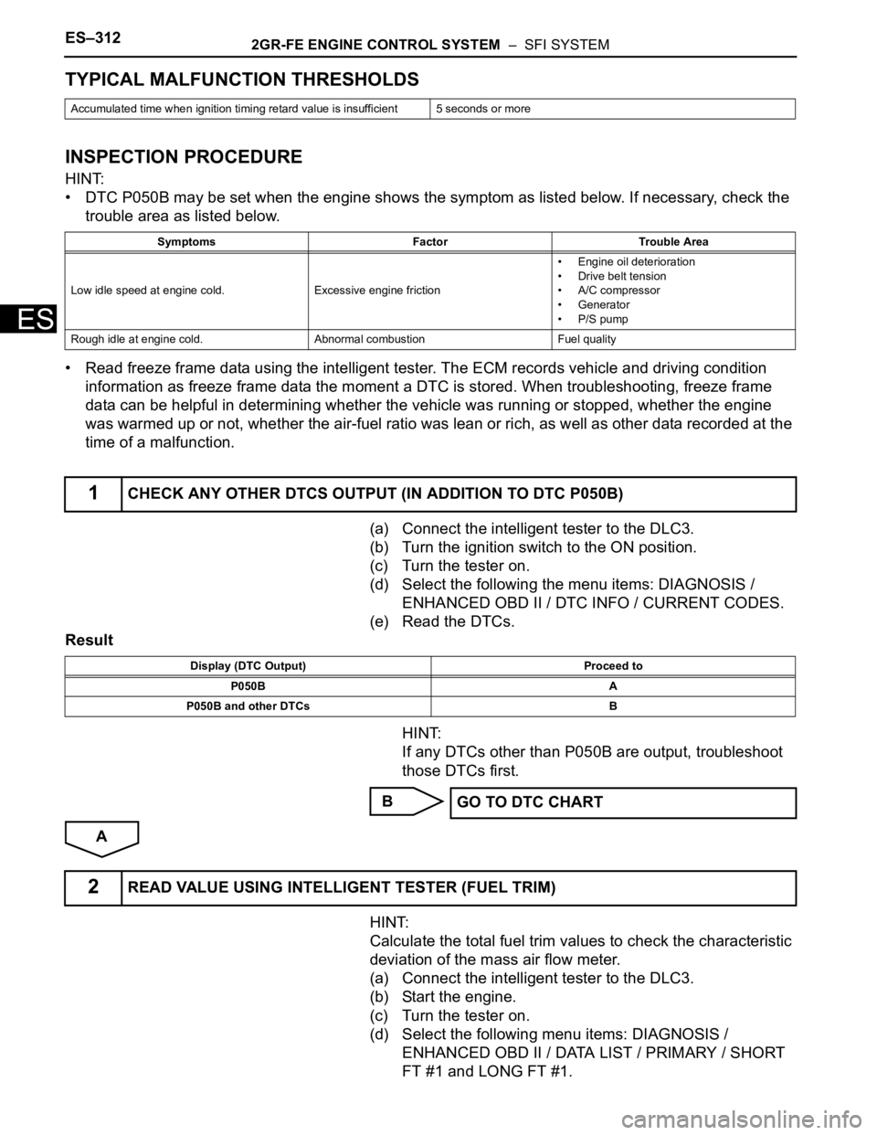
(a) Connect the intelligent tester to the DLC3.
(b) Turn the ignition switch to the ON position.
(c) Turn the tester on.
(d) Select the following the menu items: DIAGNOSIS /
ENHANCED OBD II / DTC INFO / CURRENT CODES.
(e) Read the DTCs.
Result
HINT:
If any DTCs other than P050B are output, troubleshoot
those DTCs first.
B
A
HINT:
Calculate the total fuel trim values to check the characteristic
deviation of the mass air flow meter.
(a) Connect the intelligent tester to the DLC3.
(b) Start the engine.
(c) Turn the tester on.
(d) Select the following menu items: DIAGNOSIS /
ENHANCED OBD II / DATA LIST / PRIMARY / SHORT
FT #1 and LONG FT #1.
Accumulated time when ignition timing retard value is insufficient 5 seconds or more
Symptoms Factor Trouble Area
Low idle speed at engine cold.Excessive engine friction• Engine oil deterioration
• Drive belt tension
• A/C compressor
• Generator
• P/S pump
Rough idle at engine cold. Abnormal combustion Fuel quality
1CHECK ANY OTHER DTCS OUTPUT (IN ADDITION TO DTC P050B)
Display (DTC Output) Proceed to
P050B A
P050B and other DTCs B
GO TO DTC CHART
2READ VALUE USING INTELLIGENT TESTER (FUEL TRIM)