Page 1352 of 3000
2GR-FE CHARGING – GENERATORCH–17
CH
24. REMOVE RADIATOR SUPPORT CUSHION (See page
CO-32)
25. REMOVE NO. 1 RADIATOR SUPPORT (See page CO-
32)
26. REMOVE RADIATOR ASSEMBLY WITH FAN
SHROUD AND FAN MOTOR (See page CO-33)
27. REMOVE V-RIBBED BELT (See page EM-6)
28. REMOVE GENERATOR ASSEMBLY
(a) Remove the terminal cap.
(b) Remove the nut and disconnect the wire harness
from terminal B.
(c) Disconnect the generator connector from the
generator assembly.
(d) Disconnect the connector from the compressor and
magnetic clutch.
(e) Disconnect the 2 wire harness clamps.
(f) Remove the 2 bolts.
(g) Remove the bolt from the cylinder block.
(h) Disconnect the wire harness clamp and remove the
generator assembly.
(i) Remove the bolt and wire harness clamp stay.
A162681
A162682
A162683E01
A162684
Page 1357 of 3000
2GR-FE CHARGING – GENERATORCH–17
CH
24. REMOVE RADIATOR SUPPORT CUSHION (See page
CO-32)
25. REMOVE NO. 1 RADIATOR SUPPORT (See page CO-
32)
26. REMOVE RADIATOR ASSEMBLY WITH FAN
SHROUD AND FAN MOTOR (See page CO-33)
27. REMOVE V-RIBBED BELT (See page EM-6)
28. REMOVE GENERATOR ASSEMBLY
(a) Remove the terminal cap.
(b) Remove the nut and disconnect the wire harness
from terminal B.
(c) Disconnect the generator connector from the
generator assembly.
(d) Disconnect the connector from the compressor and
magnetic clutch.
(e) Disconnect the 2 wire harness clamps.
(f) Remove the 2 bolts.
(g) Remove the bolt from the cylinder block.
(h) Disconnect the wire harness clamp and remove the
generator assembly.
(i) Remove the bolt and wire harness clamp stay.
A162681
A162682
A162683E01
A162684
Page 1368 of 3000

CH–282GR-FE CHARGING – GENERATOR
CH
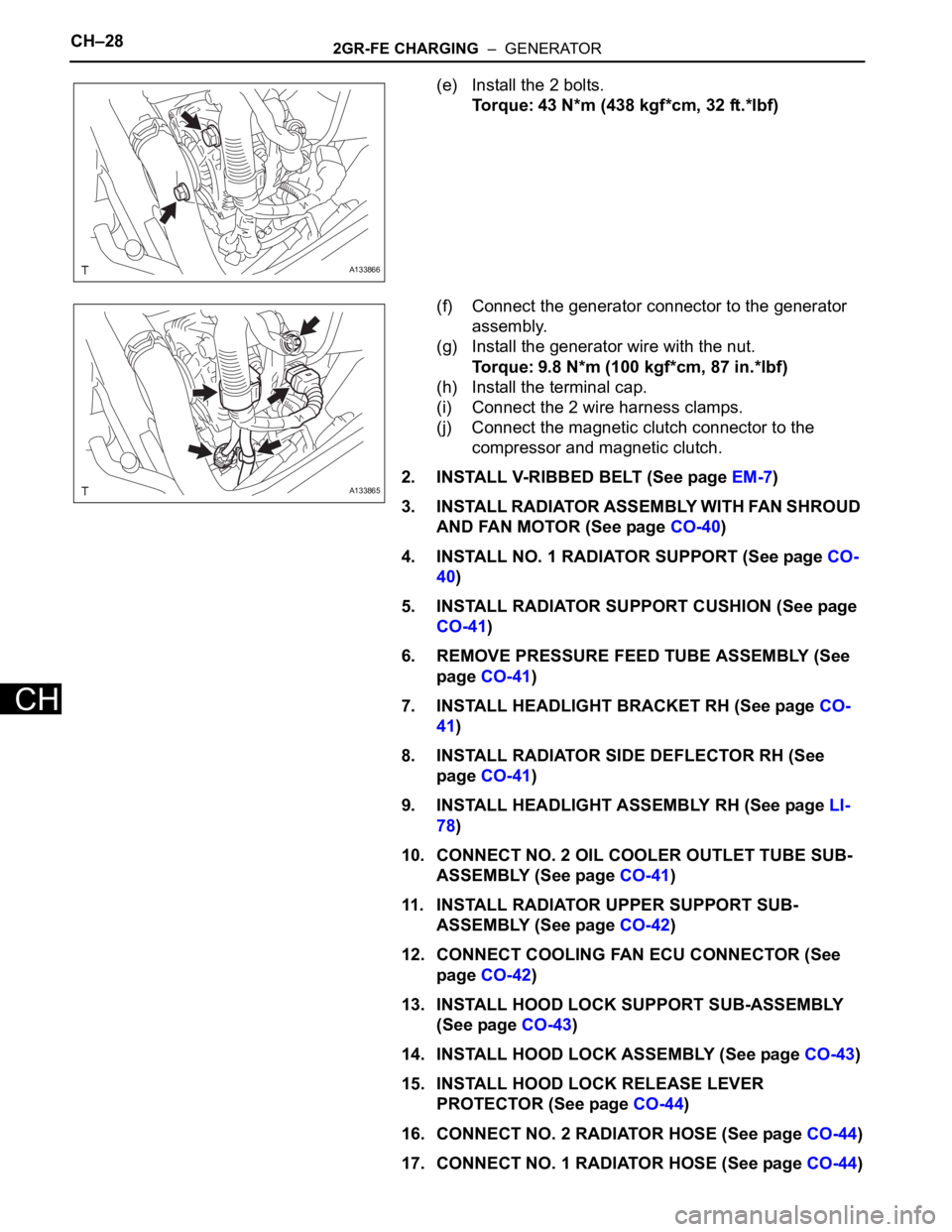
(e) Install the 2 bolts.
Torque: 43 N*m (438 kgf*cm, 32 ft.*lbf)
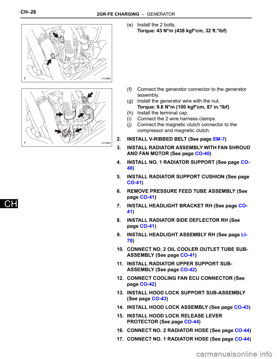
(f) Connect the generator connector to the generator
assembly.
(g) Install the generator wire with the nut.
Torque: 9.8 N*m (100 kgf*cm, 87 in.*lbf)
(h) Install the terminal cap.
(i) Connect the 2 wire harness clamps.
(j) Connect the magnetic clutch connector to the
compressor and magnetic clutch.
2. INSTALL V-RIBBED BELT (See page EM-7)
3. INSTALL RADIATOR ASSEMBLY WITH FAN SHROUD
AND FAN MOTOR (See page CO-40)
4. INSTALL NO. 1 RADIATOR SUPPORT (See page CO-
40)
5. INSTALL RADIATOR SUPPORT CUSHION (See page
CO-41)
6. REMOVE PRESSURE FEED TUBE ASSEMBLY (See
page CO-41)
7. INSTALL HEADLIGHT BRACKET RH (See page CO-
41)
8. INSTALL RADIATOR SIDE DEFLECTOR RH (See
page CO-41)
9. INSTALL HEADLIGHT ASSEMBLY RH (See page LI-
78)
10. CONNECT NO. 2 OIL COOLER OUTLET TUBE SUB-
ASSEMBLY (See page CO-41)
11. INSTALL RADIATOR UPPER SUPPORT SUB-
ASSEMBLY (See page CO-42)
12. CONNECT COOLING FAN ECU CONNECTOR (See
page CO-42)
13. INSTALL HOOD LOCK SUPPORT SUB-ASSEMBLY
(See page CO-43)
14. INSTALL HOOD LOCK ASSEMBLY (See page CO-43)
15. INSTALL HOOD LOCK RELEASE LEVER
PROTECTOR (See page CO-44)
16. CONNECT NO. 2 RADIATOR HOSE (See page CO-44)
17. CONNECT NO. 1 RADIATOR HOSE (See page CO-44)
A133866
A133865
Page 1377 of 3000

CH–282GR-FE CHARGING – GENERATOR
CH
(e) Install the 2 bolts.
Torque: 43 N*m (438 kgf*cm, 32 ft.*lbf)
(f) Connect the generator connector to the generator
assembly.
(g) Install the generator wire with the nut.
Torque: 9.8 N*m (100 kgf*cm, 87 in.*lbf)
(h) Install the terminal cap.
(i) Connect the 2 wire harness clamps.
(j) Connect the magnetic clutch connector to the
compressor and magnetic clutch.
2. INSTALL V-RIBBED BELT (See page EM-7)
3. INSTALL RADIATOR ASSEMBLY WITH FAN SHROUD
AND FAN MOTOR (See page CO-40)
4. INSTALL NO. 1 RADIATOR SUPPORT (See page CO-
40)
5. INSTALL RADIATOR SUPPORT CUSHION (See page
CO-41)
6. REMOVE PRESSURE FEED TUBE ASSEMBLY (See
page CO-41)
7. INSTALL HEADLIGHT BRACKET RH (See page CO-
41)
8. INSTALL RADIATOR SIDE DEFLECTOR RH (See
page CO-41)
9. INSTALL HEADLIGHT ASSEMBLY RH (See page LI-
78)
10. CONNECT NO. 2 OIL COOLER OUTLET TUBE SUB-
ASSEMBLY (See page CO-41)
11. INSTALL RADIATOR UPPER SUPPORT SUB-
ASSEMBLY (See page CO-42)
12. CONNECT COOLING FAN ECU CONNECTOR (See
page CO-42)
13. INSTALL HOOD LOCK SUPPORT SUB-ASSEMBLY
(See page CO-43)
14. INSTALL HOOD LOCK ASSEMBLY (See page CO-43)
15. INSTALL HOOD LOCK RELEASE LEVER
PROTECTOR (See page CO-44)
16. CONNECT NO. 2 RADIATOR HOSE (See page CO-44)
17. CONNECT NO. 1 RADIATOR HOSE (See page CO-44)
A133866
A133865
Page 2344 of 3000
TW–88TIRE AND WHEEL – TIRE PRESSURE WARNING ECU
TW
REMOVAL
NOTICE:
Before removing the tire pressure warning ECU, read the
registered transmitter IDs of all wheels and write them
down to use for re-registration of transmitter IDs (See
page TW-20).
1. DISCONNECT CABLE FROM NEGATIVE BATTERY
TERMINAL
CAUTION:
Wait at least 90 seconds after disconnecting the
cable from the negative (-) battery terminal to
prevent airbag and seat belt pretensioner activation.
2. REMOVE INSTRUMENT PANEL SAFETY PAD SUB-
ASSEMBLY
HINT:
Refer to the instructions for REMOVAL of the instrument
panel safety pad (See page IP-5).
3. REMOVE TIRE PRESSURE WARNING ECU
(a) Remove the screw.
(b) Disconnect the connector and remove the tire
pressure warning ECU.
INSTALLATION
1. INSTALL TIRE PRESSURE WARNING ECU
(a) Connect the connector to the tire pressure warning
ECU.
C156706
C156707
C156707
Page 2678 of 3000

SR–2STEERING COLUMN – STEERING SYSTEM
SR
PROBLEM SYMPTOMS TABLE
HINT:
Use the table below to help determine the cause of the
problem. Likely causes of the problem are indicated in
descending order. Check each suspected area in order.
Repair or replace the faulty parts or perform adjustments as
necessary.
STEERING SYSTEM
ON-VEHICLE INSPECTION
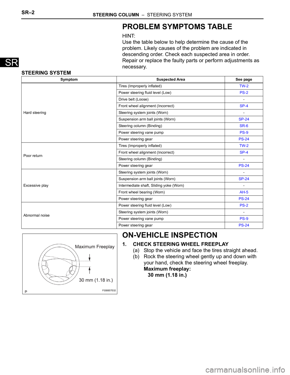
1. CHECK STEERING WHEEL FREEPLAY
(a) Stop the vehicle and face the tires straight ahead.
(b) Rock the steering wheel gently up and down with
your hand, check the steering wheel freeplay.
Maximum freeplay:
30 mm (1.18 in.)
Symptom Suspected Area See page
Hard steeringTires (Improperly inflated)TW-2
Power steering fluid level (Low)PS-2
Drive belt (Loose) -
Front wheel alignment (Incorrect)SP-4
Steering system joints (Worn) -
Suspension arm ball joints (Worn)SP-24
Steering column (Binding)SR-6
Power steering vane pumpPS-9
Power steering gearPS-24
Poor returnTires (Improperly inflated)TW-2
Front wheel alignment (Incorrect)SP-4
Steering column (Binding) -
Power steering gearPS-24
Excessive playSteering system joints (Worn) -
Suspension arm ball joints (Worn)SP-24
Intermediate shaft, Sliding yoke (Worn) -
Front wheel bearing (Worn)AH-5
Power steering gearPS-24
Abnormal noisePower steering fluid level (Low)PS-2
Steering system joints (Worn) -
Power steering vane pumpPS-9
Power steering gearPS-24
F008857E02
Page 2691 of 3000

PS–20POWER STEERING – VANE PUMP
PS
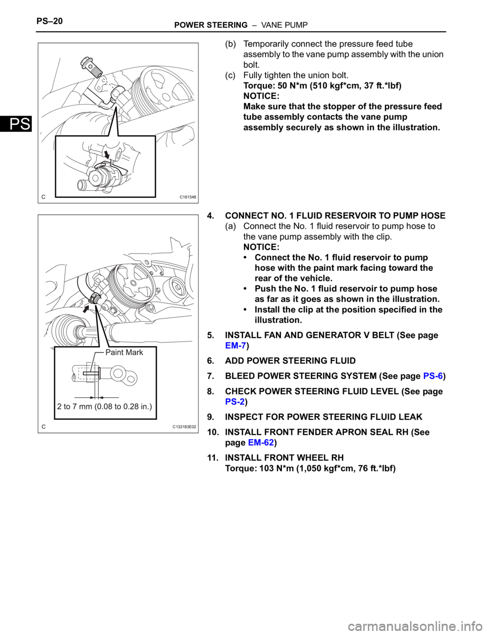
(b) Temporarily connect the pressure feed tube
assembly to the vane pump assembly with the union
bolt.
(c) Fully tighten the union bolt.
Torque: 50 N*m (510 kgf*cm, 37 ft.*lbf)
NOTICE:
Make sure that the stopper of the pressure feed
tube assembly contacts the vane pump
assembly securely as shown in the illustration.
4. CONNECT NO. 1 FLUID RESERVOIR TO PUMP HOSE
(a) Connect the No. 1 fluid reservoir to pump hose to
the vane pump assembly with the clip.
NOTICE:
• Connect the No. 1 fluid reservoir to pump
hose with the paint mark facing toward the
rear of the vehicle.
• Push the No. 1 fluid reservoir to pump hose
as far as it goes as shown in the illustration.
• Install the clip at the position specified in the
illustration.
5. INSTALL FAN AND GENERATOR V BELT (See page
EM-7)
6. ADD POWER STEERING FLUID
7. BLEED POWER STEERING SYSTEM (See page PS-6)
8. CHECK POWER STEERING FLUID LEVEL (See page
PS-2)
9. INSPECT FOR POWER STEERING FLUID LEAK
10. INSTALL FRONT FENDER APRON SEAL RH (See
page EM-62)
11. INSTALL FRONT WHEEL RH
Torque: 103 N*m (1,050 kgf*cm, 76 ft.*lbf)
C161548
C133183E02
Page 2692 of 3000
PS–24POWER STEERING – RACK AND PINION POWER STEERING GEAR
PS
REMOVAL
NOTICE:
When installing, coat the parts indicated by the arrows
with power steering fluid or molybdenum disulfide
lithium base grease (See page PS-21).
1. INSPECT CENTER FRONT WHEEL
2. REMOVE FRONT WHEEL
3. SEPARATE TIE ROD ASSEMBLY LH
SST 09628-62011
4. SEPARATE TIE ROD ASSEMBLY RH
SST 09628-62011
HINT:
Perform the same procedure on the other side.
5. SEPARATE STEERING INTERMEDIATE SHAFT
ASSEMBLY
(a) Fix the steering wheel with the seat belt.
(b) Release the 3 springs and separate the dust cover.
(c) Place matchmarks on the intermediate shaft
assembly and power steering gear assembly.
(d) Remove the bolt and separate the intermediate
shaft assembly.
6. SEPARATE FRONT STABILIZER LINK ASSEMBLY LH
7. SEPARATE FRONT STABILIZER LINK ASSEMBLY
RH
HINT:
Perform the same procedure on the other side.
D030613
D030704E03
D029986E03