Page 863 of 3000
EM–462GR-FE ENGINE MECHANICAL – ENGINE ASSEMBLY
EM
8. INSTALL NO. 2 IDLER PULLEY SUB-ASSEMBLY
(a) Install the No. 2 idler pulley sub-assembly and cover
plate with the bolt.
Torque: 43 N*m (438 kgf*cm, 32 ft.*lbf)
9. INSTALL NO. 2 TIMING GEAR COVER
(a) Install the No. 2 timing gear cover with the 2 bolts.
Torque: 6.0 N*m (61 kgf*cm, 53 in.*lbf)
10. INSTALL V-RIBBED BELT TENSIONER ASSEMBLY
(a) Temporarily install the V-ribbed belt tensioner with
the 5 bolts.
HINT:
Each bolt length is as follows:
A: 70 mm (2.76 in.)
B: 33 mm (1.30 in.)
(b) Install the V-ribbed belt tensioner by tightening the
bolt 1 and bolt 2 in the order shown in the
illustration.
Torque: 43 N*m (438 kgf*cm, 32 ft.*lbf)
(c) Tighten the other bolts.
Torque: 43 N*m (438 kgf*cm, 32 ft.*lbf)
11. INSTALL GENERATOR ASSEMBLY (See page CH-26)
12. INSTALL COOLER COMPRESSOR ASSEMBLY (See
page AC-231)
A129645E01
A132987
A129644E01
Page 877 of 3000
EM–602GR-FE ENGINE MECHANICAL – ENGINE ASSEMBLY
EM
87. INSTALL NO. 2 AIR CLEANER INLET
(a) Install the No. 2 air cleaner inlet with the 2 clamps
and 2 bolts.
Torque: 7.0 N*m (71 kgf*cm, 62 in.*lbf)
88. CONNECT VACUUM HOSES
89. INSTALL V-RIBBED BELT (See page EM-7)
A133004
A133002E01
Page 979 of 3000
2GR-FE ENGINE MECHANICAL – DRIVE BELTEM–5
EM
ENGINE
2GR-FE ENGINE MECHANICAL
DRIVE BELT
COMPONENTS
A162376E01
Page 980 of 3000

EM–62GR-FE ENGINE MECHANICAL – DRIVE BELT
EM
REMOVAL
1. REMOVE FRONT WHEEL RH
2. REMOVE FRONT FENDER APRON SEAL RH (See
page EM-26)
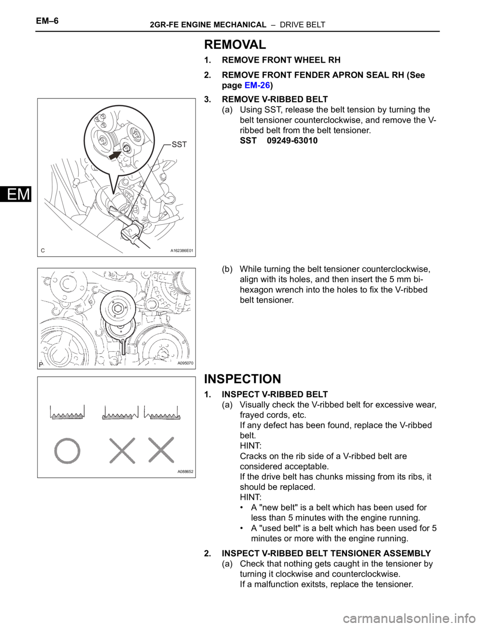
3. REMOVE V-RIBBED BELT
(a) Using SST, release the belt tension by turning the
belt tensioner counterclockwise, and remove the V-
ribbed belt from the belt tensioner.
SST 09249-63010
(b) While turning the belt tensioner counterclockwise,
align with its holes, and then insert the 5 mm bi-
hexagon wrench into the holes to fix the V-ribbed
belt tensioner.
INSPECTION
1. INSPECT V-RIBBED BELT
(a) Visually check the V-ribbed belt for excessive wear,
frayed cords, etc.
If any defect has been found, replace the V-ribbed
belt.
HINT:
Cracks on the rib side of a V-ribbed belt are
considered acceptable.
If the drive belt has chunks missing from its ribs, it
should be replaced.
HINT:
• A "new belt" is a belt which has been used for
less than 5 minutes with the engine running.
• A "used belt" is a belt which has been used for 5
minutes or more with the engine running.
2. INSPECT V-RIBBED BELT TENSIONER ASSEMBLY
(a) Check that nothing gets caught in the tensioner by
turning it clockwise and counterclockwise.
If a malfunction exitsts, replace the tensioner.
A162386E01
A095070
A088652
Page 981 of 3000

2GR-FE ENGINE MECHANICAL – DRIVE BELTEM–7
EM
INSTALLATION
1. INSTALL V-RIBBED BELT
(a) Install the V-ribbed belt.
(b) Using SST, turn the belt tensioner counterclockwise
and remove the bar.
SST 09249-63010
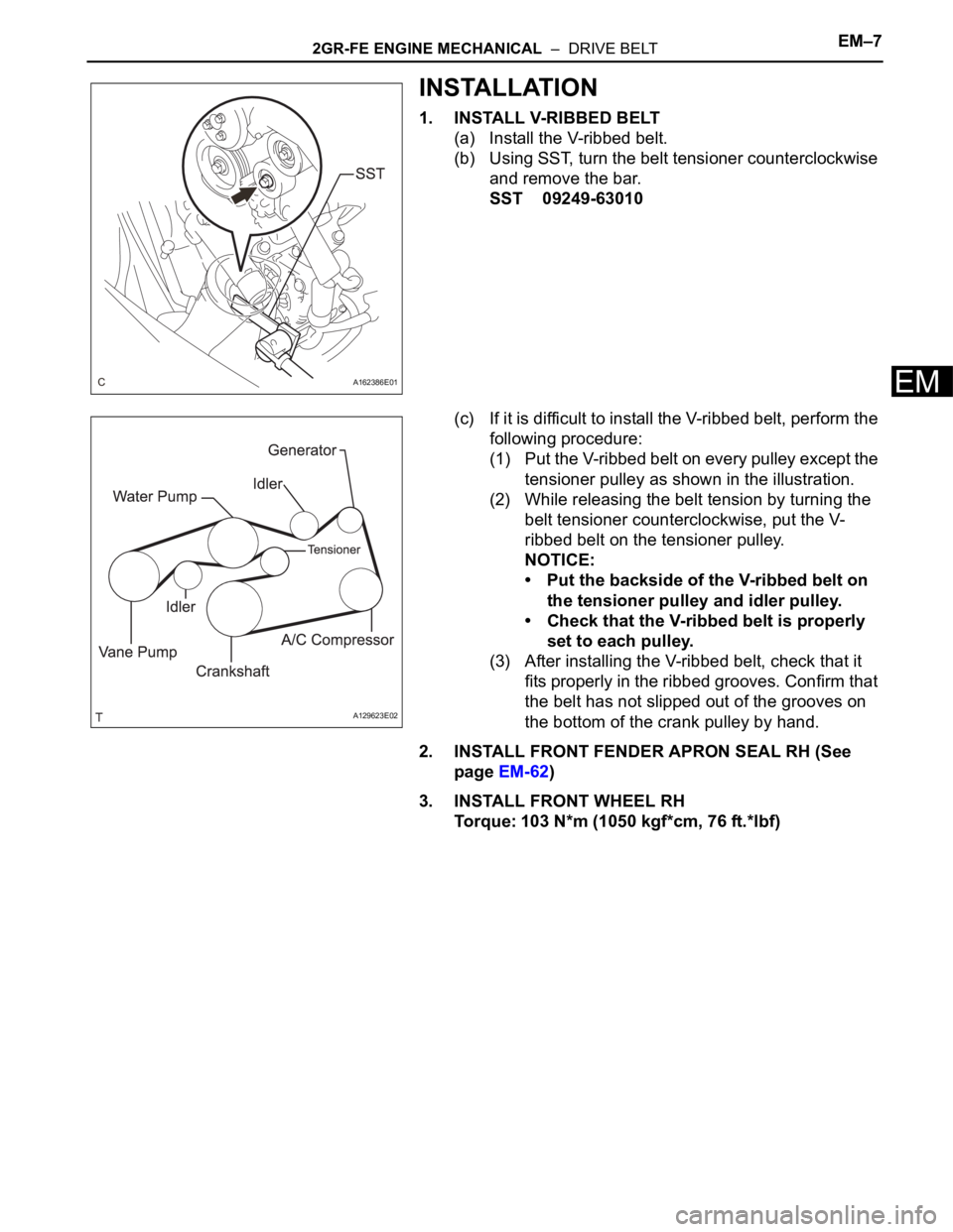
(c) If it is difficult to install the V-ribbed belt, perform the
following procedure:
(1) Put the V-ribbed belt on every pulley except the
tensioner pulley as shown in the illustration.
(2) While releasing the belt tension by turning the
belt tensioner counterclockwise, put the V-
ribbed belt on the tensioner pulley.
NOTICE:
• Put the backside of the V-ribbed belt on
the tensioner pulley and idler pulley.
• Check that the V-ribbed belt is properly
set to each pulley.
(3) After installing the V-ribbed belt, check that it
fits properly in the ribbed grooves. Confirm that
the belt has not slipped out of the grooves on
the bottom of the crank pulley by hand.
2. INSTALL FRONT FENDER APRON SEAL RH (See
page EM-62)
3. INSTALL FRONT WHEEL RH
Torque: 103 N*m (1050 kgf*cm, 76 ft.*lbf)
A162386E01
A129623E02
Page 994 of 3000
2GR-FE ENGINE MECHANICAL – ENGINE ASSEMBLYEM–35
EM
(b) Remove the 6 bolts, 2 nuts, and frame side rail
plates RH and LH.
(c) Remove the 6 bolts, 2 nuts, and front suspension
member brace rear RH and LH.
(d) Operate the engine lifter, then remove the engine
assembly from the vehicle.
NOTICE:
Make sure that the engine is clear of all wiring
and hoses.
62. REMOVE V-RIBBED BELT (See page EM-6)
63. REMOVE VANE PUMP ASSEMBLY
(a) Disconnect the power steering oil pressure switch
connector.
(b) Remove the 2 nuts.
(c) Loosen the bolt A.
(d) Remove the bolt B.
(e) Remove the bolt A and vane pump assembly.
64. REMOVE FRONT STABILIZER BAR (for 4WD)
HINT:
See page SP-35.
65. REMOVE POWER STEERING LINK
(a) Remove the 2 bolts and power steering link with
vane pump.
A162364
A162363
A155024
A139216E01
Page 1000 of 3000
2GR-FE ENGINE MECHANICAL – ENGINE ASSEMBLYEM–41
EM
92. REMOVE ENGINE MOUNTING BRACKET RR (for
4WD)
(a) Remove the 3 bolts and engine mounting bracket
RR.
93. REMOVE GENERATOR ASSEMBLY (See page CH-17)
94. REMOVE COOLER COMPRESSOR ASSEMBLY
95. REMOVE V-RIBBED BELT TENSIONER ASSEMBLY
(a) Remove the 5 bolts and V-ribbed belt tensioner
assembly.
96. REMOVE NO. 2 TIMING GEAR COVER
(a) Remove the 2 bolts and No. 2 timing gear cover.
97. REMOVE NO. 2 IDLER PULLEY SUB-ASSEMBLY
(a) Remove the bolt, plate and No. 2 idler pulley sub-
assembly.
98. REMOVE WATER PUMP PULLEY (See page CO-12)
A143881
A129644
A132987
A129645E01
Page 1005 of 3000
EM–462GR-FE ENGINE MECHANICAL – ENGINE ASSEMBLY
EM
8. INSTALL NO. 2 IDLER PULLEY SUB-ASSEMBLY
(a) Install the No. 2 idler pulley sub-assembly and cover
plate with the bolt.
Torque: 43 N*m (438 kgf*cm, 32 ft.*lbf)
9. INSTALL NO. 2 TIMING GEAR COVER
(a) Install the No. 2 timing gear cover with the 2 bolts.
Torque: 6.0 N*m (61 kgf*cm, 53 in.*lbf)
10. INSTALL V-RIBBED BELT TENSIONER ASSEMBLY
(a) Temporarily install the V-ribbed belt tensioner with
the 5 bolts.
HINT:
Each bolt length is as follows:
A: 70 mm (2.76 in.)
B: 33 mm (1.30 in.)
(b) Install the V-ribbed belt tensioner by tightening the
bolt 1 and bolt 2 in the order shown in the
illustration.
Torque: 43 N*m (438 kgf*cm, 32 ft.*lbf)
(c) Tighten the other bolts.
Torque: 43 N*m (438 kgf*cm, 32 ft.*lbf)
11. INSTALL GENERATOR ASSEMBLY (See page CH-26)
12. INSTALL COOLER COMPRESSOR ASSEMBLY (See
page AC-231)
A129645E01
A132987
A129644E01