Page 222 of 3000

SS–28SERVICE SPECIFICATIONS – U151E AUTOMATIC TRANSAXLE
SS
Flange thickness Mark
1 1.8 mm (0.071 in.)
2 1.9 mm (0.075 in.)
3 2.0 mm (0.079 in.)
4 2.1 mm (0.083 in.)
5 2.2 mm (0.087 in.)
6 2.3 mm (0.091 in.)
7 2.4 mm (0.094 in.)
8 2.5 mm (0.098 in.)
U/D planetary gear
Preload (at 60 rpm) 0.50 to 1.42 N*m (5.1 to 14.5 kgf*cm, 0.06 to 0.17 in.*lbf)
Front planetary gear
Turning torque (at 60 rpm) New
Bearing0.51 to 1.02 N*m (5.1 to 10.0 kgf*cm, 4.4 to 8.7 in.*lbf)
Used
Bearing0.26 to 0.51 N*m (2.7 to 5.2 kgf*cm, 2.3 to 4.5 in.*lbf)
Input shaft
End play0.262 to 1.249 mm (0.0103 to 0.0492 in.)
Transaxle rear cover
Bearing press fit depth 20.55 to 21.25 mm (0.8091 to 0.8366 in.)
Transmission valve body
Valve body installation bolt length A 41 mm (1.614 in.)
B 57 mm (2.244 in.)
C 25 mm (0.984 in.)
Accumulator
Spring Free length/Outer diameter Color
B
3Inner 62.00 (2.4409) / 15.50 (0.610) Purple
Outer 74.23 (2.9224) / 16.50 (0.649) Purple
C
260.96 (2.3999) / 14.10 (0.555) Yellow
C
372.20 (2.8425) / 19.0 (0.748) Colorless
Front differential (U151E)
Backlash0.05 to 0.20 mm (0.0020 to 0.0079 in.)
Thrust washer thickness Mark
- 1.625 mm (0.0640 in.)
- 1.725 mm (0.0679 in.)
- 1.825 mm (0.0719 in.)
Preload (at 60 rpm) New
bearing0.20 to 0.69 N*m (2.0 to 7.0 kgf*cm, 1.8 to 6.1 in.*lbf)
Used
bearing0.10 to 0.35 N*m (1.0 to 3.6 kgf*cm, 0.9 to 3.1 in.*lbf) 1st & reverse brake
Page 227 of 3000

SS–34SERVICE SPECIFICATIONS – U151F AUTOMATIC TRANSAXLE
SS
Flange thickness Mark
1 3.0 mm (0.118 in.)
2 3.2 mm (0.126 in.)
3 3.4 mm (0.134 in.)
1st & reverse brake
Pack clearance1.16 to 1.35 mm (0.0457 to 0.0531in.)
Return spring free length15.53 mm (0.6114 in.)
Flange thickness Mark
1 1.8 mm (0.071 in.)
2 1.9 mm (0.075 in.)
3 2.0 mm (0.079 in.)
4 2.1 mm (0.083 in.)
5 2.2 mm (0.087 in.)
6 2.3 mm (0.091 in.)
7 2.4 mm (0.094 in.)
8 2.5 mm (0.098 in.)
U/D planetary gear
Preload (at 60 rpm) 0.50 to 1.42 N*m (5.1 to 14.5 kgf*cm, 0.06 to 0.17 in.*lbf)
Front planetary gear
Turning torque (at 60 rpm) New
Bearing0.51 to 1.02 N*m (5.1 to 10.0 kgf*cm, 4.4 to 8.7 in.*lbf)
Used
Bearing0.26 to 0.51 N*m (2.7 to 5.2 kgf*cm, 2.3 to 4.5 in.*lbf)
Input shaft
End play0.262 to 1.249 mm (0.0103 to 0.0492 in.)
Transaxle rear cover
Bearing press fit depth 20.55 to 21.25 mm (0.8091 to 0.8366 in.)
Transmission valve body
Valve body installation bolt length A 41 mm (1.614 in.)
B 57 mm (2.244 in.)
C 25 mm (0.984 in.)
Accumulator
Spring Free length/Outer diameter Color
B
3Inner 62.00 (2.4409) / 15.50 (0.610) Purple
Outer 74.23 (2.9224) / 16.50 (0.649) Purple
C
260.96 (2.3999) / 14.10 (0.555) Yellow
C
372.20 (2.8425) / 19.0 (0.748) Colorless
Front differential (U151F)
Side gear backlash 0.05 to 0.20 mm (0.0020 to 0.0079 in.) U/D brake
Page 354 of 3000

ES–282GR-FE ENGINE CONTROL SYSTEM – SFI SYSTEM
ES
• Vehicle was driven in the city area (or on free-
way) for 10 minutes or more.
(b) Monitor Conditions
(1) Turn the ignition switch off and wait for 6 hours.
HINT:
Do not start the engine until checking Readiness
Monitor status. If the engine is started, the step
described above must be repeated.
(c) Monitor Status
(1) Connect an intelligent tester to the DLC3.
(2) Turn the ignition switch to the ON position.
(3) Turn the tester or scan tool ON.
(4) Check the Readiness Monitor status displayed
on the tester or scan tool.
If the status does not switch to COMPL
(complete), restart the engine, make sure that
the preconditions have been met, and then
perform the Monitor Conditions again.
4. A/F SENSOR AND HO2S MONITORS
(a) Preconditions
The monitor will not run unless:
• 2 minutes or more have elapsed since the engine
was started.
• The Engine Coolant Temperature (ECT) is 75
C
(167
F) or more.
• Cumulative driving time at a vehicle speed of 30
mph (48 km/h) or more exceeds 6 minutes.
• Air-fuel ratio feedback control is performed.
• Fuel-cut control is performed for 8 seconds or
more (for the Rear HO2 Sensor Monitor).
(b) Drive Pattern for front A/F sensor and HO2 sensor.
(1) Connect an intelligent tester to the DLC3.
(2) Turn the ignition switch to the ON position.
(3) Turn the tester ON.
(4) Clear the DTCs.
(5) Start the engine, and warm it up until the ECT
reaches 75
C (167F) or higher.
(6) Drive the vehicle at 38 mph (60 km/h) or more
for at least 10 minutes.
(7) Change the transmission to the 2nd gear.
(8) Accelerate the vehicle to 40 mph (64 km/h) or
more by depressing the accelerator pedal for at
least 10 seconds (Procedure "A").
(9) Soon after performing procedure "A" above,
release the accelerator pedal for at least 4
seconds without depressing the brake pedal, in
order to execute fuel-cut control (Procedure "B").
(10) Allow the vehicle to decelerate until the vehicle
speed declines to less than 6 mph (10 km/h)
(Procedure "C").
(11) Repeat procedures from "A" through "C" above
at least 3 times in one driving cycle.
Page 804 of 3000

ES–282GR-FE ENGINE CONTROL SYSTEM – SFI SYSTEM
ES
• Vehicle was driven in the city area (or on free-
way) for 10 minutes or more.
(b) Monitor Conditions
(1) Turn the ignition switch off and wait for 6 hours.
HINT:
Do not start the engine until checking Readiness
Monitor status. If the engine is started, the step
described above must be repeated.
(c) Monitor Status
(1) Connect an intelligent tester to the DLC3.
(2) Turn the ignition switch to the ON position.
(3) Turn the tester or scan tool ON.
(4) Check the Readiness Monitor status displayed
on the tester or scan tool.
If the status does not switch to COMPL
(complete), restart the engine, make sure that
the preconditions have been met, and then
perform the Monitor Conditions again.
4. A/F SENSOR AND HO2S MONITORS
(a) Preconditions
The monitor will not run unless:
• 2 minutes or more have elapsed since the engine
was started.
• The Engine Coolant Temperature (ECT) is 75
C
(167
F) or more.
• Cumulative driving time at a vehicle speed of 30
mph (48 km/h) or more exceeds 6 minutes.
• Air-fuel ratio feedback control is performed.
• Fuel-cut control is performed for 8 seconds or
more (for the Rear HO2 Sensor Monitor).
(b) Drive Pattern for front A/F sensor and HO2 sensor.
(1) Connect an intelligent tester to the DLC3.
(2) Turn the ignition switch to the ON position.
(3) Turn the tester ON.
(4) Clear the DTCs.
(5) Start the engine, and warm it up until the ECT
reaches 75
C (167F) or higher.
(6) Drive the vehicle at 38 mph (60 km/h) or more
for at least 10 minutes.
(7) Change the transmission to the 2nd gear.
(8) Accelerate the vehicle to 40 mph (64 km/h) or
more by depressing the accelerator pedal for at
least 10 seconds (Procedure "A").
(9) Soon after performing procedure "A" above,
release the accelerator pedal for at least 4
seconds without depressing the brake pedal, in
order to execute fuel-cut control (Procedure "B").
(10) Allow the vehicle to decelerate until the vehicle
speed declines to less than 6 mph (10 km/h)
(Procedure "C").
(11) Repeat procedures from "A" through "C" above
at least 3 times in one driving cycle.
Page 1538 of 3000

AX–150U151E AUTOMATIC TRANSAXLE – SHIFT LEVER
AX
ADJUSTMENT
1. INSPECT SHIFT LEVER POSITION
(a) When shifting from P to R position only with ignition
switch ON and brake pedal, make sure that the
shifting lever moves smoothly and can be
moderately operated.
(b) When starting engine, make sure that the vehicle
moves forward when shifting from N to D position
and moves rearward when shifting to R position.
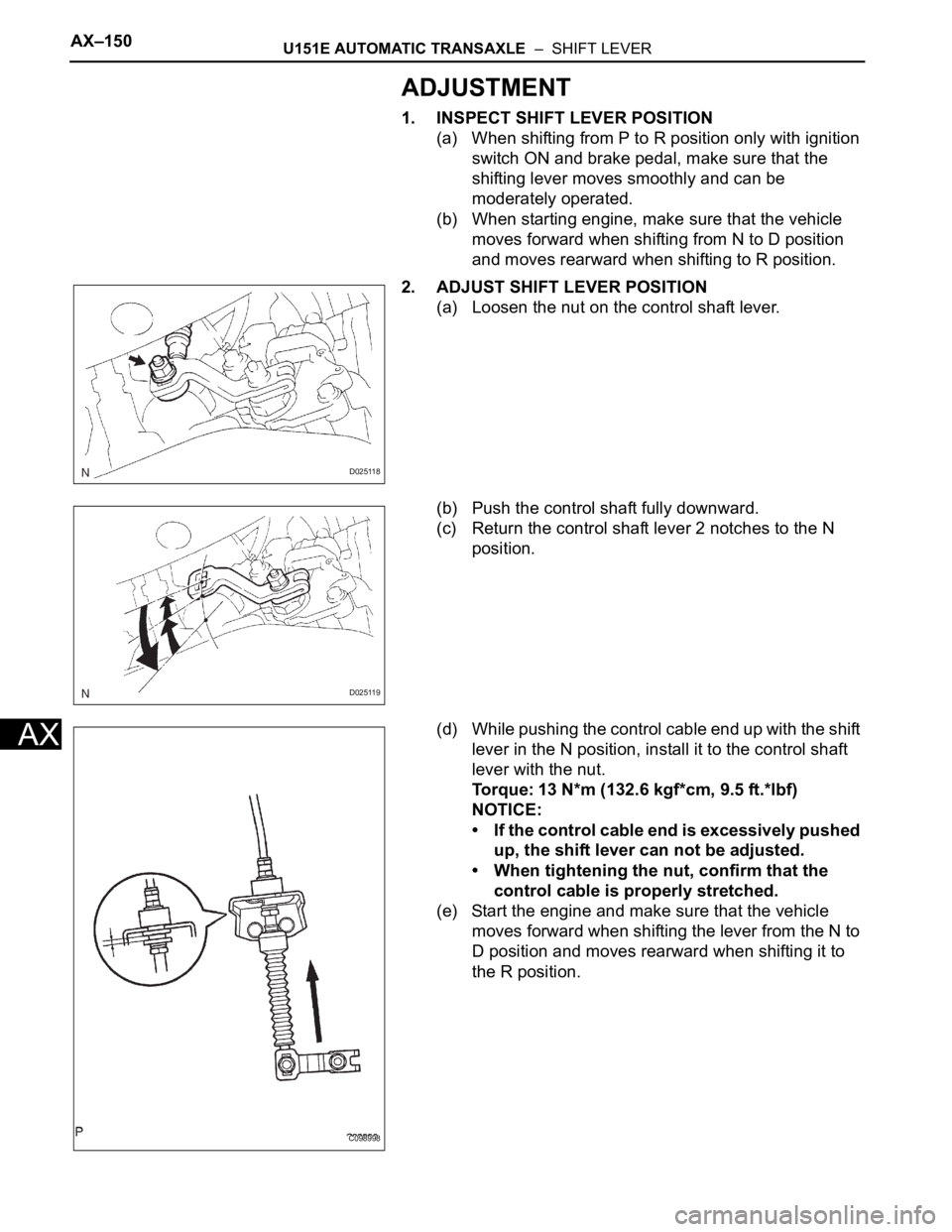
2. ADJUST SHIFT LEVER POSITION
(a) Loosen the nut on the control shaft lever.
(b) Push the control shaft fully downward.
(c) Return the control shaft lever 2 notches to the N
position.
(d) While pushing the control cable end up with the shift
lever in the N position, install it to the control shaft
lever with the nut.
Torque: 13 N*m (132.6 kgf*cm, 9.5 ft.*lbf)
NOTICE:
• If the control cable end is excessively pushed
up, the shift lever can not be adjusted.
• When tightening the nut, confirm that the
control cable is properly stretched.
(e) Start the engine and make sure that the vehicle
moves forward when shifting the lever from the N to
D position and moves rearward when shifting it to
the R position.
D025118
D025119
C098998
Page 1548 of 3000

AX–156U151E AUTOMATIC TRANSAXLE – TRANSMISSION CONTROL CABLE ASSEMBLY
AX
ADJUSTMENT
1. INSPECT SHIFT LEVER POSITION
(a) When shifting from P to R position only with ignition
switch ON and brake pedal, make sure that the
shifting lever moves smoothly and can be
moderately operated.
(b) When starting engine, make sure that the vehicle
moves forward when shifting from N to D position
and moves rearward when shifting to R position.
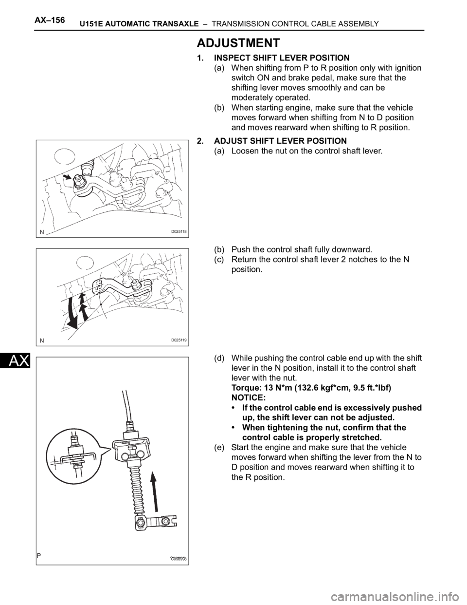
2. ADJUST SHIFT LEVER POSITION
(a) Loosen the nut on the control shaft lever.
(b) Push the control shaft fully downward.
(c) Return the control shaft lever 2 notches to the N
position.
(d) While pushing the control cable end up with the shift
lever in the N position, install it to the control shaft
lever with the nut.
Torque: 13 N*m (132.6 kgf*cm, 9.5 ft.*lbf)
NOTICE:
• If the control cable end is excessively pushed
up, the shift lever can not be adjusted.
• When tightening the nut, confirm that the
control cable is properly stretched.
(e) Start the engine and make sure that the vehicle
moves forward when shifting the lever from the N to
D position and moves rearward when shifting it to
the R position.
D025118
D025119
C098998
Page 1568 of 3000
U151E AUTOMATIC TRANSAXLE – AUTOMATIC TRANSAXLE UNITAX–189
AX
48. REMOVE GOVERNOR APPLY GASKET NO.1
(a) Using a screwdriver, remove the 3 apply gaskets.
49. REMOVE BRAKE APPLY TUBE
(a) Remove the bolt, clamp and brake apply tube.
(b) Remove the clutch apply tube.
(c) Remove the brake apply tube from the clamp.
NOTICE:
Do not bend the tubes.
50. REMOVE DIRECT CLUTCH ASSEMBLY
(a) Remove the thrust bearing and the direct clutch
assembly from the transaxle case.
51. REMOVE OVERDRIVE DIRECT CLUTCH HUB SUB-
ASSEMBLY
(a) Remove the thrust bearing race, thrust bearing and
overdrive direct clutch hub from the planetary gear
assembly.
52. INSPECT OVERDRIVE DIRECT CLUTCH DRUM SUB-
ASSEMBLY
HINT:
(See page AX-198)
53. REMOVE REAR PLANETARY SUN GEAR ASSEMBLY
(a) Remove the rear planetary sun gear assembly from
the transaxle case.
D026390
D026391E03
D026403E02
D026392E03
D026714E02
Page 1570 of 3000
U151E AUTOMATIC TRANSAXLE – AUTOMATIC TRANSAXLE UNITAX–191
AX
56. REMOVE PLANETARY CARRIER THRUST WASHER
NO.1
(a) Remove the planetary carrier thrust washer No.1
from the planetary gear assembly.
57. REMOVE 2ND BRAKE CLUTCH DISC
(a) Using a screwdriver, remove the snap ring.
(b) Remove the flange, 4 discs and 4 plates from the
transaxle case.
58. INSPECT 2ND BRAKE CLUTCH DISC
HINT:
(See page AX-198)
59. REMOVE 2ND BRAKE PISTON ASSEMBLY
(a) Using a screwdriver, remove the snap ring.
(b) Remove the 2ND brake piston assembly from the
transaxle case.
60. REMOVE REAR PLANETARY GEAR ASSEMBLY
(a) Using a screwdriver, remove the snap ring.
D026394E02
D026395E01
D008058E01
D026396E04
D003616E01