Page 1571 of 3000
AX–192U151E AUTOMATIC TRANSAXLE – AUTOMATIC TRANSAXLE UNIT
AX
(b) Remove the rear planetary gear assembly from the
transaxle case.
61. REMOVE INPUT SUN GEAR
(a) Remove the 2 thrust needle roller bearings, thrust
bearing race No.2 and the input sun gear from the
transaxle case.
62. REMOVE 1ST AND REVERSE BRAKE CLUTCH DISC
(a) Remove the flange, 6 discs and 6 plates from the
transaxle case.
63. INSPECT 1ST AND REVERSE BRAKE CLUTCH DISC
HINT:
(See page AX-198)
64. REMOVE FRONT PLANETARY GEAR ASSEMBLY
(a) Using a chisel and hammer, unstake the lock
washer.
NOTICE:
Push down all claws of the washer. Otherwise
the SST cannot be fully pressed against the nut,
and cannot loosen the nut.
(b) Using SST, remove the nut.
SST 09387-00030, 09387-00080
D026591E02
D003873E02
D026397
D003595E01
D003596E01
Page 1589 of 3000

U151E AUTOMATIC TRANSAXLE – AUTOMATIC TRANSAXLE UNITAX–203
AX
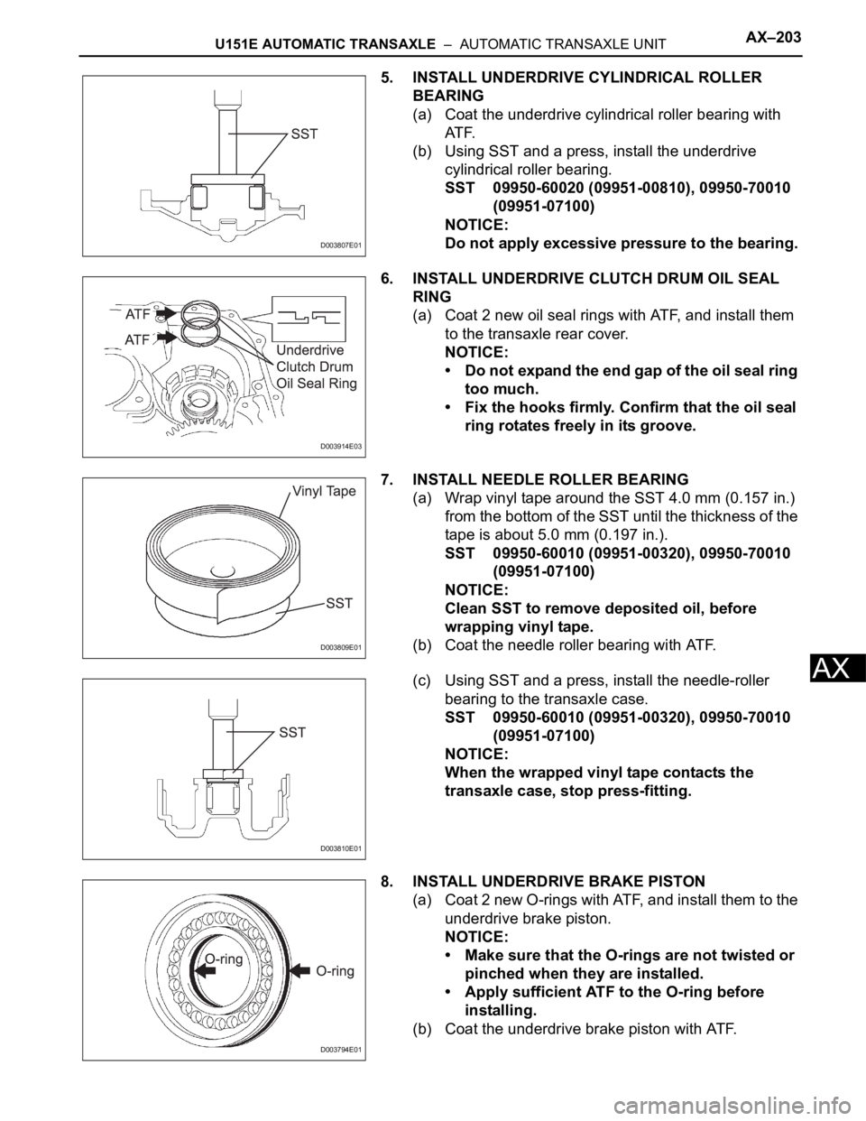
5. INSTALL UNDERDRIVE CYLINDRICAL ROLLER
BEARING
(a) Coat the underdrive cylindrical roller bearing with
AT F.
(b) Using SST and a press, install the underdrive
cylindrical roller bearing.
SST 09950-60020 (09951-00810), 09950-70010
(09951-07100)
NOTICE:
Do not apply excessive pressure to the bearing.
6. INSTALL UNDERDRIVE CLUTCH DRUM OIL SEAL
RING
(a) Coat 2 new oil seal rings with ATF, and install them
to the transaxle rear cover.
NOTICE:
• Do not expand the end gap of the oil seal ring
too much.
• Fix the hooks firmly. Confirm that the oil seal
ring rotates freely in its groove.
7. INSTALL NEEDLE ROLLER BEARING
(a) Wrap vinyl tape around the SST 4.0 mm (0.157 in.)
from the bottom of the SST until the thickness of the
tape is about 5.0 mm (0.197 in.).
SST 09950-60010 (09951-00320), 09950-70010
(09951-07100)
NOTICE:
Clean SST to remove deposited oil, before
wrapping vinyl tape.
(b) Coat the needle roller bearing with ATF.
(c) Using SST and a press, install the needle-roller
bearing to the transaxle case.
SST 09950-60010 (09951-00320), 09950-70010
(09951-07100)
NOTICE:
When the wrapped vinyl tape contacts the
transaxle case, stop press-fitting.
8. INSTALL UNDERDRIVE BRAKE PISTON
(a) Coat 2 new O-rings with ATF, and install them to the
underdrive brake piston.
NOTICE:
• Make sure that the O-rings are not twisted or
pinched when they are installed.
• Apply sufficient ATF to the O-ring before
installing.
(b) Coat the underdrive brake piston with ATF.
D003807E01
D003914E03
D003809E01
D003810E01
D003794E01
Page 1595 of 3000

U151E AUTOMATIC TRANSAXLE – AUTOMATIC TRANSAXLE UNITAX–209
AX
18. INSTALL REAR PLANETARY GEAR ASSEMBLY
(a) Install the rear planetary gear assembly to the rear
planetary ring gear.
(b) Using a screwdriver, install the snap ring.
NOTICE:
Confirm that the snap ring is fixed in the groove
of the 1st and reverse brake hub correctly.
19. INSTALL 1ST AND REVERSE BRAKE CLUTCH DISC
(a) Coat the 6 discs with ATF.
(b) Install the 7 plates and 6 discs.
NOTICE:
Make sure that the plates, discs, and flange are
installed as shown in the illustration.
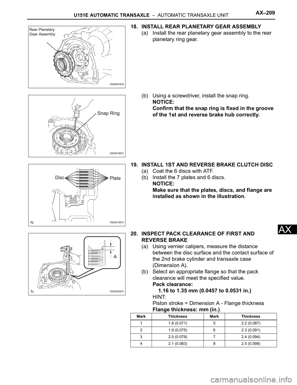
20. INSPECT PACK CLEARANCE OF FIRST AND
REVERSE BRAKE
(a) Using vernier calipers, measure the distance
between the disc surface and the contact surface of
the 2nd brake cylinder and transaxle case
(Dimension A).
(b) Select an appropriate flange so that the pack
clearance will meet the specified value.
Pack clearance:
1.16 to 1.35 mm (0.0457 to 0.0531 in.)
HINT:
Piston stroke = Dimension A - Flange thickness
Flange thickness: mm (in.)
D026591E02
D003616E01
D026413E01
D026452E01
Mark Thickness Mark Thickness
1 1.8 (0.071) 5 2.2 (0.087)
2 1.9 (0.075) 6 2.3 (0.091)
3 2.0 (0.079) 7 2.4 (0.094)
4 2.1 (0.083) 8 2.5 (0.098)
Page 1598 of 3000

AX–212U151E AUTOMATIC TRANSAXLE – AUTOMATIC TRANSAXLE UNIT
AX
(b) Coat the bearing with yellow petrolatum, and install
the bearing onto the rear planetary sun gear.
Bearing diameter: mm (in.)
(c) Install the rear planetary sun gear assembly to the
rear planetary gear.
NOTICE:
Installing the rear planetary sun gear assembly,
make sure that the B1 discs are engaged.
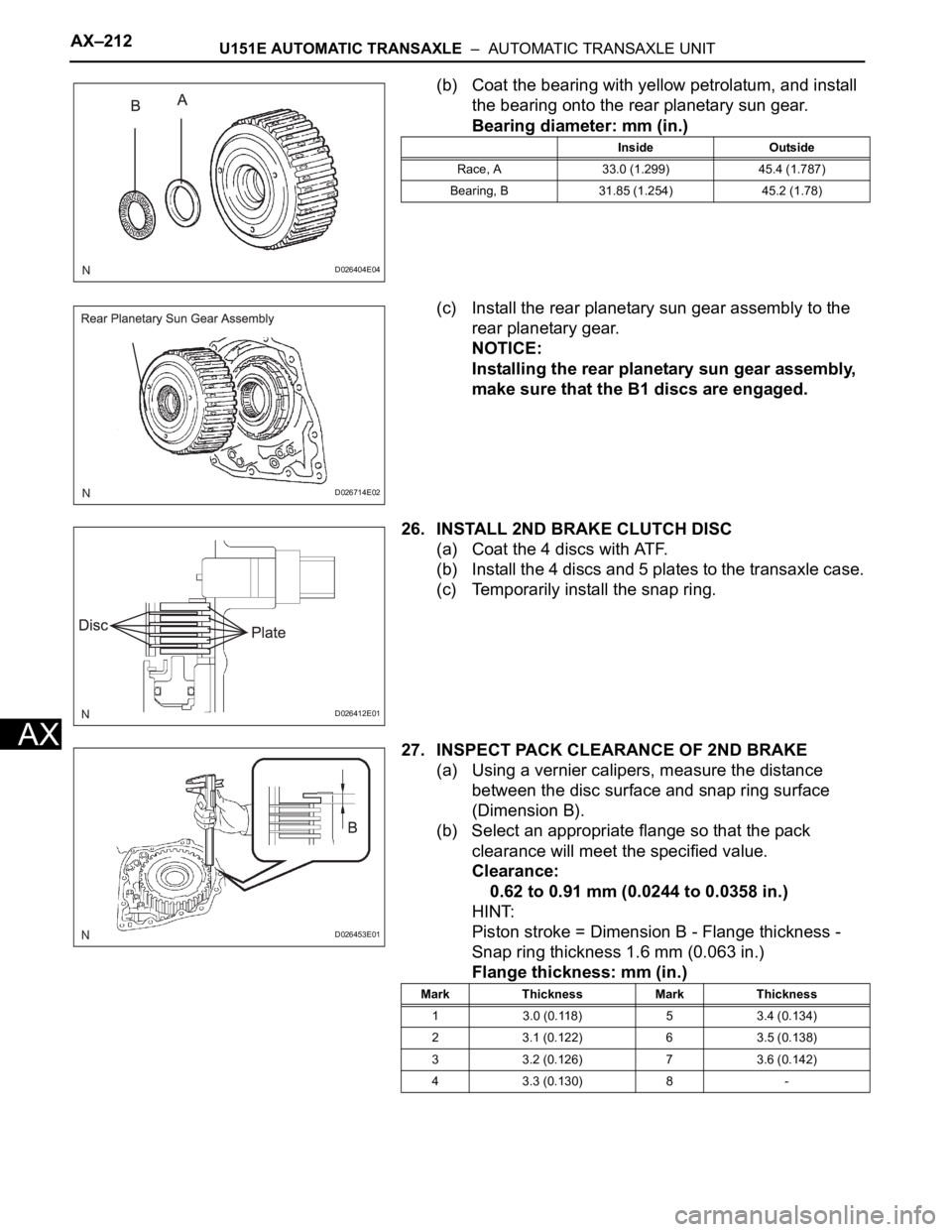
26. INSTALL 2ND BRAKE CLUTCH DISC
(a) Coat the 4 discs with ATF.
(b) Install the 4 discs and 5 plates to the transaxle case.
(c) Temporarily install the snap ring.
27. INSPECT PACK CLEARANCE OF 2ND BRAKE
(a) Using a vernier calipers, measure the distance
between the disc surface and snap ring surface
(Dimension B).
(b) Select an appropriate flange so that the pack
clearance will meet the specified value.
Clearance:
0.62 to 0.91 mm (0.0244 to 0.0358 in.)
HINT:
Piston stroke = Dimension B - Flange thickness -
Snap ring thickness 1.6 mm (0.063 in.)
Flange thickness: mm (in.)
D026404E04
Inside Outside
Race, A 33.0 (1.299) 45.4 (1.787)
Bearing, B 31.85 (1.254) 45.2 (1.78)
D026714E02
D026412E01
D026453E01
Mark Thickness Mark Thickness
1 3.0 (0.118) 5 3.4 (0.134)
2 3.1 (0.122) 6 3.5 (0.138)
3 3.2 (0.126) 7 3.6 (0.142)
4 3.3 (0.130) 8 -
Page 1633 of 3000
U151E AUTOMATIC TRANSAXLE – AUTOMATIC TRANSAXLE UNITAX–189
AX
48. REMOVE GOVERNOR APPLY GASKET NO.1
(a) Using a screwdriver, remove the 3 apply gaskets.
49. REMOVE BRAKE APPLY TUBE
(a) Remove the bolt, clamp and brake apply tube.
(b) Remove the clutch apply tube.
(c) Remove the brake apply tube from the clamp.
NOTICE:
Do not bend the tubes.
50. REMOVE DIRECT CLUTCH ASSEMBLY
(a) Remove the thrust bearing and the direct clutch
assembly from the transaxle case.
51. REMOVE OVERDRIVE DIRECT CLUTCH HUB SUB-
ASSEMBLY
(a) Remove the thrust bearing race, thrust bearing and
overdrive direct clutch hub from the planetary gear
assembly.
52. INSPECT OVERDRIVE DIRECT CLUTCH DRUM SUB-
ASSEMBLY
HINT:
(See page AX-198)
53. REMOVE REAR PLANETARY SUN GEAR ASSEMBLY
(a) Remove the rear planetary sun gear assembly from
the transaxle case.
D026390
D026391E03
D026403E02
D026392E03
D026714E02
Page 1635 of 3000
U151E AUTOMATIC TRANSAXLE – AUTOMATIC TRANSAXLE UNITAX–191
AX
56. REMOVE PLANETARY CARRIER THRUST WASHER
NO.1
(a) Remove the planetary carrier thrust washer No.1
from the planetary gear assembly.
57. REMOVE 2ND BRAKE CLUTCH DISC
(a) Using a screwdriver, remove the snap ring.
(b) Remove the flange, 4 discs and 4 plates from the
transaxle case.
58. INSPECT 2ND BRAKE CLUTCH DISC
HINT:
(See page AX-198)
59. REMOVE 2ND BRAKE PISTON ASSEMBLY
(a) Using a screwdriver, remove the snap ring.
(b) Remove the 2ND brake piston assembly from the
transaxle case.
60. REMOVE REAR PLANETARY GEAR ASSEMBLY
(a) Using a screwdriver, remove the snap ring.
D026394E02
D026395E01
D008058E01
D026396E04
D003616E01
Page 1636 of 3000
AX–192U151E AUTOMATIC TRANSAXLE – AUTOMATIC TRANSAXLE UNIT
AX
(b) Remove the rear planetary gear assembly from the
transaxle case.
61. REMOVE INPUT SUN GEAR
(a) Remove the 2 thrust needle roller bearings, thrust
bearing race No.2 and the input sun gear from the
transaxle case.
62. REMOVE 1ST AND REVERSE BRAKE CLUTCH DISC
(a) Remove the flange, 6 discs and 6 plates from the
transaxle case.
63. INSPECT 1ST AND REVERSE BRAKE CLUTCH DISC
HINT:
(See page AX-198)
64. REMOVE FRONT PLANETARY GEAR ASSEMBLY
(a) Using a chisel and hammer, unstake the lock
washer.
NOTICE:
Push down all claws of the washer. Otherwise
the SST cannot be fully pressed against the nut,
and cannot loosen the nut.
(b) Using SST, remove the nut.
SST 09387-00030, 09387-00080
D026591E02
D003873E02
D026397
D003595E01
D003596E01
Page 1841 of 3000

AX–150U151F AUTOMATIC TRANSAXLE – SHIFT LEVER
AX
ADJUSTMENT
1. INSPECT SHIFT LEVER POSITION
(a) When shifting from P to R position only with ignition
switch ON and brake pedal, make sure that the
shifting lever moves smoothly and can be
moderately operated.
(b) When starting engine, make sure that the vehicle
moves forward when shifting from N to D position
and moves rearward when shifting to R position.
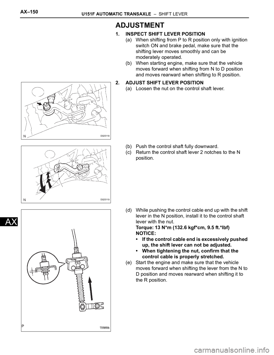
2. ADJUST SHIFT LEVER POSITION
(a) Loosen the nut on the control shaft lever.
(b) Push the control shaft fully downward.
(c) Return the control shaft lever 2 notches to the N
position.
(d) While pushing the control cable end up with the shift
lever in the N position, install it to the control shaft
lever with the nut.
Torque: 13 N*m (132.6 kgf*cm, 9.5 ft.*lbf)
NOTICE:
• If the control cable end is excessively pushed
up, the shift lever can not be adjusted.
• When tightening the nut, confirm that the
control cable is properly stretched.
(e) Start the engine and make sure that the vehicle
moves forward when shifting the lever from the N to
D position and moves rearward when shifting it to
the R position.
D025118
D025119
C098998