Page 7 of 3000
PP–6PREPARATION – 2GR-FE ENGINE MECHANICAL
PP
EQUIPMENT
Abrasive compound
Brush
Caliper gauge
Carbide cutter (30
)
Carbide cutter (45
)
Carbide cutter (60
)
Carbide cutter (75
)
Connecting rod aligner
Cylinder gauge
Dial indicator
Dye penetrant
Engine tune-up tester
Groove cleaning tool
Heater
Micrometer
Piston ring compressor
Piston ring expander
Plastigage
Precision straight edge
Press
Reamer (5.5 mm)
Ridge reamer
Soft brush
Solvent
Spring tester
Steel square
Thermometer
To r q u e w r e n c h
Torx socket wrench
Valve seat cutter
Valve guide bushing brush
V-block
Vernier calipers
Wire brush
Bar
Chain Block
CO/HC meter
Compression gauge
Dial indicator with magnetic base
Engine Sling Device
Feeler gauge
Radiator cap tester
Slide calipers
Tachometer
Timing light
Wooden block
Deep socket wrench
Screwdriver
Hammer
Page 358 of 3000

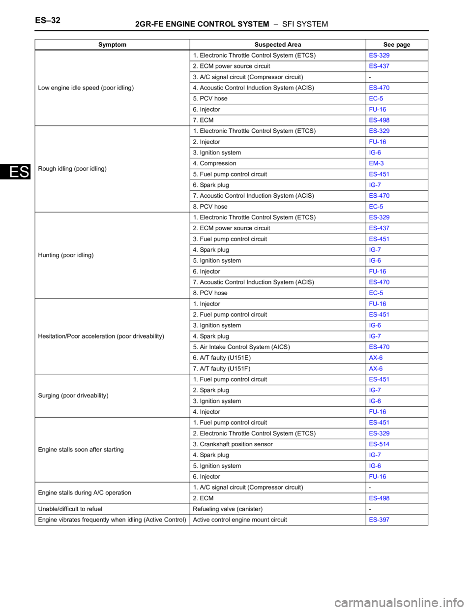
ES–322GR-FE ENGINE CONTROL SYSTEM – SFI SYSTEM
ES
Low engine idle speed (poor idling)1. Electronic Throttle Control System (ETCS)ES-329
2. ECM power source circuitES-437
3. A/C signal circuit (Compressor circuit) -
4. Acoustic Control Induction System (ACIS)ES-470
5. PCV hoseEC-5
6. InjectorFU-16
7. ECMES-498
Rough idling (poor idling)1. Electronic Throttle Control System (ETCS)ES-329
2. InjectorFU-16
3. Ignition systemIG-6
4. CompressionEM-3
5. Fuel pump control circuitES-451
6. Spark plugIG-7
7. Acoustic Control Induction System (ACIS)ES-470
8. PCV hoseEC-5
Hunting (poor idling)1. Electronic Throttle Control System (ETCS)ES-329
2. ECM power source circuitES-437
3. Fuel pump control circuitES-451
4. Spark plugIG-7
5. Ignition systemIG-6
6. InjectorFU-16
7. Acoustic Control Induction System (ACIS)ES-470
8. PCV hoseEC-5
Hesitation/Poor acceleration (poor driveability)1. InjectorFU-16
2. Fuel pump control circuitES-451
3. Ignition systemIG-6
4. Spark plugIG-7
5. Air Intake Control System (AICS)ES-470
6. A/T faulty (U151E)AX-6
7. A/T faulty (U151F)AX-6
Surging (poor driveability)1. Fuel pump control circuitES-451
2. Spark plugIG-7
3. Ignition systemIG-6
4. InjectorFU-16
Engine stalls soon after starting1. Fuel pump control circuitES-451
2. Electronic Throttle Control System (ETCS)ES-329
3. Crankshaft position sensorES-514
4. Spark plugIG-7
5. Ignition systemIG-6
6. InjectorFU-16
Engine stalls during A/C operation1. A/C signal circuit (Compressor circuit) -
2. ECMES-498
Unable/difficult to refuel Refueling valve (canister) -
Engine vibrates frequently when idling (Active Control) Active control engine mount circuitES-397 Symptom Suspected Area See page
Page 510 of 3000

ES–2042GR-FE ENGINE CONTROL SYSTEM – SFI SYSTEM
ES
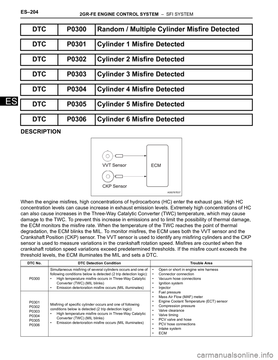
DESCRIPTION
When the engine misfires, high concentrations of hydrocarbons (HC) enter the exhaust gas. High HC
concentration levels can cause increase in exhaust emission levels. Extremely high concentrations of HC
can also cause increases in the Three-Way Catalytic Converter (TWC) temperature, which may cause
damage to the TWC. To prevent this increase in emissions and to limit the possibility of thermal damage,
the ECM monitors the misfire rate. When the temperature of the TWC reaches the point of thermal
degradation, the ECM blinks the MIL. To monitor misfires, the ECM uses both the VVT sensor and the
Crankshaft Position (CKP) sensor. The VVT sensor is used to identify any misfiring cylinders and the CKP
sensor is used to measure variations in the crankshaft rotation speed. Misfires are counted when the
crankshaft rotation speed variations exceed predetermined thresholds. If the misfire count exceeds the
threshold levels, the ECM illuminates the MIL and sets a DTC.
DTC P0300 Random / Multiple Cylinder Misfire Detected
DTC P0301 Cylinder 1 Misfire Detected
DTC P0302 Cylinder 2 Misfire Detected
DTC P0303 Cylinder 3 Misfire Detected
DTC P0304 Cylinder 4 Misfire Detected
DTC P0305 Cylinder 5 Misfire Detected
DTC P0306 Cylinder 6 Misfire Detected
DTC No. DTC Detection Condition Trouble Area
P0300Simultaneous misfiring of several cylinders occurs and one of
following conditions below is detected (2 trip detection logic):
• High temperature misfire occurs in Three-Way Catalytic
Converter (TWC) (MIL blinks)
• Emission deterioration misfire occurs (MIL illuminates)• Open or short in engine wire harness
• Connector connection
• Vacuum hose connections
• Ignition system
• Injector
• Fuel pressure
• Mass Air Flow (MAF) meter
• Engine Coolant Temperature (ECT) sensor
• Compression pressure
• Valve clearance
• Valve timing
• PCV valve and hose
• PCV hose connections
• Intake system
•ECM P0301
P0302
P0303
P0304
P0305
P0306Misfiring of specific cylinder occurs and one of following
conditions below is detected (2 trip detection logic):
• High temperature misfire occurs in Three-Way Catalytic
Converter (TWC) (MIL blinks)
• Emission deterioration misfire occurs (MIL illuminates)
A093767E07
Page 810 of 3000

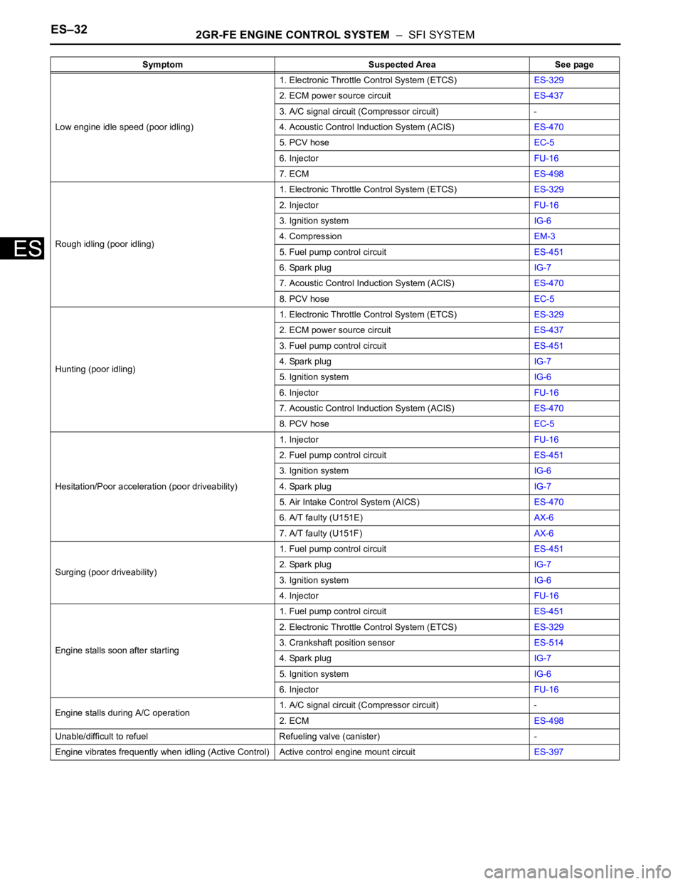
ES–322GR-FE ENGINE CONTROL SYSTEM – SFI SYSTEM
ES
Low engine idle speed (poor idling)1. Electronic Throttle Control System (ETCS)ES-329
2. ECM power source circuitES-437
3. A/C signal circuit (Compressor circuit) -
4. Acoustic Control Induction System (ACIS)ES-470
5. PCV hoseEC-5
6. InjectorFU-16
7. ECMES-498
Rough idling (poor idling)1. Electronic Throttle Control System (ETCS)ES-329
2. InjectorFU-16
3. Ignition systemIG-6
4. CompressionEM-3
5. Fuel pump control circuitES-451
6. Spark plugIG-7
7. Acoustic Control Induction System (ACIS)ES-470
8. PCV hoseEC-5
Hunting (poor idling)1. Electronic Throttle Control System (ETCS)ES-329
2. ECM power source circuitES-437
3. Fuel pump control circuitES-451
4. Spark plugIG-7
5. Ignition systemIG-6
6. InjectorFU-16
7. Acoustic Control Induction System (ACIS)ES-470
8. PCV hoseEC-5
Hesitation/Poor acceleration (poor driveability)1. InjectorFU-16
2. Fuel pump control circuitES-451
3. Ignition systemIG-6
4. Spark plugIG-7
5. Air Intake Control System (AICS)ES-470
6. A/T faulty (U151E)AX-6
7. A/T faulty (U151F)AX-6
Surging (poor driveability)1. Fuel pump control circuitES-451
2. Spark plugIG-7
3. Ignition systemIG-6
4. InjectorFU-16
Engine stalls soon after starting1. Fuel pump control circuitES-451
2. Electronic Throttle Control System (ETCS)ES-329
3. Crankshaft position sensorES-514
4. Spark plugIG-7
5. Ignition systemIG-6
6. InjectorFU-16
Engine stalls during A/C operation1. A/C signal circuit (Compressor circuit) -
2. ECMES-498
Unable/difficult to refuel Refueling valve (canister) -
Engine vibrates frequently when idling (Active Control) Active control engine mount circuitES-397 Symptom Suspected Area See page
Page 891 of 3000
EM–862GR-FE ENGINE MECHANICAL – ENGINE UNIT
EM
28. REMOVE TIMING CHAIN CASE OIL SEAL
(a) Using a screwdriver, pry out the timing chain case
oil seal.
HINT:
Tape the screwdriver tip before use.
29. SET NO. 1 CYLINDER TO TDC / COMPRESSION
(a) Temporarily tighten the pulley set bolt.
(b) Set the timing mark on the crank angle sensor plate
to the RH block bore center line (TDC /
compression).
(c) Check that the timing marks of the camshaft timing
gears are aligned with those of the bearing cap as
shown in the illustration.
If not, turn the crankshaft 1 revolution (360
) and
align the timing marks as above.
A108818E01
A129691E01
A129692E02
Page 938 of 3000
2GR-FE ENGINE MECHANICAL – ENGINE UNITEM–129
EM
(b) Using a piston ring expander, install the
compression ring as shown in the illustration.
(c) Position the piston rings so that the ring ends are as
shown in the illustration.
NOTICE:
Do not align the ring ends.
6. INSTALL CRANKSHAFT BEARING
(a) Clean the main journal and both surfaces of the
bearing.
NOTICE:
Main bearings come in widths between 18.0 mm
(0.709 in.) and 21.0 mm (0.827 in.). Install the
21.0 mm (0.827 in.) bearings in the No. 1 and No.
4 cylinder block journal positions with the main
bearing cap. Install the 18.0 mm (0.709 in.)
bearings in the No. 2 and No. 3 positions.
A131880E03
A131881E01
A124282E02
Page 949 of 3000

EM–1402GR-FE ENGINE MECHANICAL – ENGINE UNIT
EM
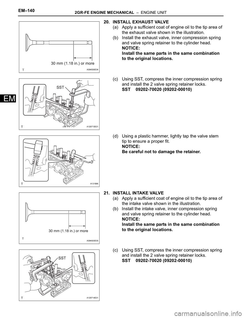
20. INSTALL EXHAUST VALVE
(a) Apply a sufficient coat of engine oil to the tip area of
the exhaust valve shown in the illustration.
(b) Install the exhaust valve, inner compression spring
and valve spring retainer to the cylinder head.
NOTICE:
Install the same parts in the same combination
to the original locations.
(c) Using SST, compress the inner compression spring
and install the 2 valve spring retainer locks.
SST 09202-70020 (09202-00010)
(d) Using a plastic hammer, lightly tap the valve stem
tip to ensure a proper fit.
NOTICE:
Be careful not to damage the retainer.
21. INSTALL INTAKE VALVE
(a) Apply a sufficient coat of engine oil to the tip area of
the intake valve shown in the illustration.
(b) Install the intake valve, inner compression spring
and valve spring retainer to the cylinder head.
NOTICE:
Install the same parts in the same combination
to the original locations.
(c) Using SST, compress the inner compression spring
and install the 2 valve spring retainer locks.
SST 09202-70020 (09202-00010)
A094936E04
A129715E01
A131896
A094935E05
A129714E01
Page 1033 of 3000
EM–862GR-FE ENGINE MECHANICAL – ENGINE UNIT
EM
28. REMOVE TIMING CHAIN CASE OIL SEAL
(a) Using a screwdriver, pry out the timing chain case
oil seal.
HINT:
Tape the screwdriver tip before use.
29. SET NO. 1 CYLINDER TO TDC / COMPRESSION
(a) Temporarily tighten the pulley set bolt.
(b) Set the timing mark on the crank angle sensor plate
to the RH block bore center line (TDC /
compression).
(c) Check that the timing marks of the camshaft timing
gears are aligned with those of the bearing cap as
shown in the illustration.
If not, turn the crankshaft 1 revolution (360
) and
align the timing marks as above.
A108818E01
A129691E01
A129692E02